2
Joerns®Liing and Repositioning
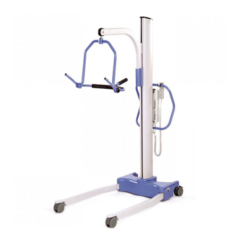
HPL400 and HML400 Hoyer Patient Li
© 2014 Joerns Healthcare • 000-3258 RevE • 14-2632
Joerns Healthcare 1_Art Direction_Joerns Beds_700 Series_UltraCare 8page
5/2007_Page 2 of 8
2
Table of Contents
Assembly...................................................................................................................................2
Specications ............................................................................................................................4
Troubleshooting Power Unit ......................................................................................................4
Operation...................................................................................................................................5
Partner Sling Information...........................................................................................................6
Lifter Maintenance Checklist .....................................................................................................7
Warranty ....................................................................................................................................8
This manual contains important safety and
maintenance instructions. Please read it carefully
before using your patient lifter and refer to it as
often as needed for safe and efcient use.
If you have any questions regarding the safe use
and/or assembly, maintenance or specications
of your patient lifter, you should call Joerns
Healthcare toll-free at 800.826.0270.
For service and repair, remember your authorized
Hoyer dealer is able to provide the assistance
you need. Save this manual for future reference.
For non-homecare lifters, your maintenance
department should keep this manual.
Caution: For patient use, refer to the separate
manual, “How to Use a Patient Lifter.” If you did not
receive a copy or need additional copies, contact
Joerns Healthcare at 800.826.0270.
Assembly
For Installation for adjustable
U-Base Lifters
Recommended Tools: 3/4" and 1/2" wrench, 3/16"
hex wrench
Warning: All shoulder bolts must engage through
the bracket on both sides. If bolt is not fully
engaged, misalignment and premature failure may
result. Worn parts could fail, resulting in injury to
patient/caregiver (Figure 1).
Warning: The large thrust washer must be inserted
on the cradle hanger post (Figure 1). If washer
is not present, the cradle hanger post and cradle
center may wear prematurely. Warn cradle parts
could fail, resulting in injury to resident/caregiver.
Hanger post should protrude cradle center by
1/16th inch (Figure 1).
1. Carefully unpack lifter in the following order:
a. Remove the outside top of the box.
b. Remove the three inside top llers from the
box. NOTE: If the lifter is a power version,
be careful with the center ller, it contains
the electronics.
c. Remove base and adjustment handle from
the box.
d. Remove bottom ller from the box.
e. Remove cradle and mast assembly from
the box.
2. Apply a thin layer for grease to all bolts.
3. Place base of lifter on a hard even surface with
the wheels contacting the surface. Insert the
mast in sleeve of base making sure that it is
fully engaged. Tighten the mask lock bolt
(Figure 2). Make sure boom points in the same
direction as base legs. Keep mast locked at all
times except while storing.
4. Place adjustment handle into socket as shown
(Figure 2). Pull adjustment handle back to
unlock. Handle can be moved to the right to
widen the base to 39 1/2" or to the left to narrow
the base to 24".
5. Remove boom from ller and attach to top of
mast as shown (Figure 2).
6. Attach to of actuator to boom with cap and
hardware. Note: Attach rst to hole on bracket
(Figure 2), second hole can be used for heavier
patients to ease the load on actuator, however
the vertical lifting range will lose 4 inches.
7. Remove actuator from ller and attach top
of actuator to mast and bottom to boom with
hardware (Figure 1).
8. Attach cradle to the end of boom with cap and
hardware (Figure 2).
9. Brake is provided on rear caster for parking only.
To lock caster, step on cam lever, located on
side of caster. To unlock brake, step on highest
cam lever.
