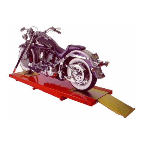
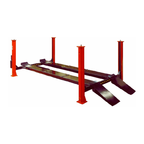
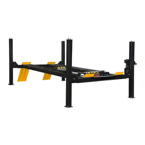
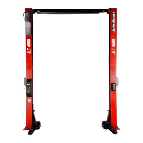
John Bean BAYSAVER II User manual

READ THIS INSTRUCTION MANUAL THOROUGHLY BEFORE
INSTALLING, OPERATING, SERVICING OR MAINTAINING
THE LIFT. SAVE THIS MANUAL.
OCT 2008 REV.-
INSTALLATION
and OPERATION
MANUAL
BAYSAVER II
9000LB Models
48109B / 48209B
Flushmount Models
48109BFM / 48209BFM
(144” W/B / 172” W/B)
12000LB Model
4812205AF 172” W/B
BAYSAVER II
9000LB Models
48109B / 48209B
Flushmount Models
48109BFM / 48209BFM
(144” W/B / 172” W/B)
12000LB Model
4812205AF 172” W/B
309 EXCHANGE AVENUE, CONWAY, ARKANSAS, 72032
TEL: 501-450-1500 FAX: 501-450-1585
6-1269

2 of 40
TABLE OF CONTENTS PAGE
1. SAFETY INSTRUCTIONS ................................................................................................3
2. SAFETY WARNING DECALS .........................................................................................5
3. SPECIFICATIONS..............................................................................................................6
4. CONTENTS..........................................................................................................................7
5. TOOLS REQUIRED FOR INSTALLATION..................................................................7
6. INSTALLATION INSTRUCTIONS .................................................................................8
6.1 BAY LAYOUT..................................................................................................................9
6.2 UNPACKING PROCEDURE.......................................................................................10
6.3 HYDRAULIC INSTALLATION..................................................................................11
6.4 ELECTRICAL INSTALLATION................................................................................13
6.5 BLEEDING PROCEDURE...........................................................................................14
6.6 AIR LINE INSTALLATION ........................................................................................14
6.7 MECHANICAL SAFETY INSTALLATION: ............................................................15
6.8 PNEUMATIC SYSTEMS INSTALLATION ..............................................................17
6.9 LEVELING PROCEDURE...........................................................................................18
6.10 ANCHORING PROCEDURE...................................................................................19
6.11 COVERS, WHEEL STOPS AND APPROACH RAMPS.......................................21
7. OPERATING INSTRUCTIONS......................................................................................22
7.1 RAISING THE LIFT .....................................................................................................22
7.2 LOWERING THE LIFT................................................................................................23
8. FINAL CHECK OF ASSEMBLED LIFT.......................................................................24
9. OPERATION TEST WITH VEHICLE ..........................................................................25
10. RECOMMENDED MAINTENANCE.............................................................................26
11. PARTS MANUAL .............................................................................................................28
11.1 BAYSAVER ASSEMBLY..........................................................................................28
11.2 BAYSAVER - PART LIST........................................................................................29
11.3 BAYSAVER HYDRAULICS.....................................................................................31
11.4 BAYSAVER - HYDRAULICS PART LIST.............................................................32
11.5 BAYSAVER OPTIONS..............................................................................................33
11.6 BAYSAVER - OPTIONS PART LIST......................................................................34
11.7 BAYSAVER CONSOLE ............................................................................................35
11.8 BAYSAVER CONSOLE PART LIST ......................................................................36
11.9 9000 LB BAYSAVER POWERPACK......................................................................37
11.10 9,000 LB BAYSAVER POWERPACK PARTS LIST.............................................38
11.11 12,000 LB BAYSAVER POWERPACK...................................................................38
11.12 12,000 LB BAYSAVER POWER PACK - PARTS LIST........................................39
3 of 40
1. SAFETY INSTRUCTIONS
When using this lift, basic safety precautions should always be followed, including the following:
1. Read all instructions in this manual and on the lift.
2. Inspect lift daily. Do not operate if it malfunctions or problems have been encountered.
3. Never attempt to overload the lift. The manufacturer’s rated capacity is shown on the
identification label on the power side column. Do not override the operating controls or
the safety devices.
4. Only trained and authorized personnel should operate the lift. Do not allow customers or
bystanders to operate the lift or be in the lift area.
5. CAUTION! Never work under the lift unless the mechanical safety locks are
engaged.
6. Always keep the lift area free of obstruction and debris. Grease and oil spills should
always be cleaned up immediately.
7. Never raise vehicle with passengers inside.
8. Before lowering check area for any obstructions.
9. To protect against the risk of fire, do not operate lift in the vicinity of opencontainers of
flammable liquids.
10. Adequate ventilation should be provided when working on internal combustion
engines.
11. Never open hydraulic lines under pressure.
SAVE THESE INSTRUCTIONS

4 of 40
Installation shall be performed in accordance with ANSO/ALI ALIS, Safety Requirements for
Installation and Service of Automotive Lifts.
For additional safety instructions regarding lifting, lift types, warning labels, preparing to lift,
vehicle spotting, vehicle lifting, maintaining load stability, emergency procedures, vehicle
lowering, lift limitations, lift maintenance, good shop practices, installation, operator training
and owner/employer responsibilities, please refer to “Lifting It Right” (ALI/SM) and “Safety
Tips” (ALI/ST).
For additional instruction on general requirements for lift operation, please refer to “Automotive
Lift-Safety Requirements For Operation, Inspection and Maintenance” (ANSI/ALI ALOIM).
ATTENTION! This lift is intended for indoor installation only. It is
prohibited to install this product outdoors. Operating environment
temperature range should be 41 – 104 °F (5 – 40 °C). Failure to adhere will
result in decertification, loss of warranty, and possible damage to the
equipment.

5 of 40
2. SAFETY WARNING DECALS
Be sure the operator is aware and underastands all safety warning lables and follows them
accordingly.

6 of 40
3. SPECIFICATIONS
Maximum Capacity: 9000 lbs. 4100 kg 12000 lbs. 5450 kg
Overall Width: 84” 2134 mm 92” 2337 mm
Width Between Runways: 36” 914 mm 36” 914 mm
Overall Length (144” W/B): 234” 5944mm N/A N/A
Overall Length (172” W/B): 264” 6706 mm 264” 6706 mm
Max. Raised Height: 72” 1829 mm 72” 1829 mm
Min. Lowered Height: 8 3/4” 222 mm 8 3/4” 222 mm
Lifting Time: 60 Sec. 60 Sec.
Power Requirements: 230V, 1Ph, 60Hz 230V, 1Ph, 60Hz
Air Requirements: 90 – 120 psi shop air 90 – 120 psi shop air
Shipping Weight (144” W/B): 3450 lbs. 1565 kg N/A N/A
Shipping Weight (172” W/B): 3560 lbs. 1615 kg 4980 lbs. 1615 kg
Figure 1 -Lift Dimensions

7 of 40
4. CONTENTS
The complete lift is contained in two (2) packages:
1. The main structural components are pre-assembled and packaged one on top of the other.
1. The remaining parts are packed in an accessory box. Refer to the packing slip inside the
accessory box for a list contents.
Main Structural Components:
1pc. - Left Side Main Frame Assembly; Runway, Scissors and Base Frame
1pc. - Right Side Main Frame Assembly; Runway, Scissors and Base Frame
Note: Hydraulic lines in base frames have been factory installed
Other Structural Components:
1pc. – Console and accessory box. (See accessory box list for contents)
1pc. – Grout container
1pc. – Customer care kit including manuals
5. TOOLS REQUIRED FOR INSTALLATION
* Rotary Hammer Drill or Similar, ¼" and ½” Concrete Drill Bits
* 4' Level
* SAE Wrenches and Sockets
* Hammer
* Pry Bar
* Chalk Line
* Tape Measure
* Side Cutters
* Screw Drivers
* Hydraulic Fluid ISO 32 (10 weight hydraulic oil) - (20 liters / 5.3Gal.)
* Funnel
* Utility Knife
Recommended:
* Laser Leveler
* Plumb Bob
* Impact Gun
* Boom and/or Engine Hoist
* 8’ Sling

8 of 40
6. INSTALLATION INSTRUCTIONS
When the lift arrives on site, please read the owner’s manual completely. Check the contents to
make sure no parts are missing before starting installation. Gather all the tools listed and make
sure the installation instructions are fully understood before commencing with the installation.
IMPORTANT: It is the user’s responsibility to provide a satisfactory installation area for
the lift. Lifts should only be installed on level concrete floors with a minimum thickness of
five (5) inches or 130 mm. Concrete must have a minimum strength of 4000 psi or 30 MPa
and should be aged thirty (30) days prior to installation. Please consult the architect,
contractor or engineer if doubt exists as to the strength and feasibility of the floor to enable
proper lift installation and operation.
It is the user’s responsibility to provide all wiring for electrical hook-up prior to installation
and to insure that the electrical installation conforms to local building codes. Where
required, it is the user’s responsibility to provide an electrical isolation switch located in
close proximity to the lift that will enable emergency stop capability and isolate electrical
power from the lift for any servicing requirements.

9 of 40
6.1 BAY LAYOUT
Figure 2 - Typical Bay Layout (Surface Mount)
IMPORTANT: DO NOT UNBOLT SHIPPING CLAMPS HOLDING EACH MAIN
FRAME ASSEMBLY TOGETHER UNTIL INSTRUCTED TO DO SO.
NOTE: Leave any additional room for any desired aisle or work area. Recommended clearance
around the lift is a minimum of three (3) feet. Ensure clearance conforms to local building and
fire codes.
Recommended overhead clearance is a minimum of twelve (12) foot ceiling providing 6 feet for
the maximum lift height and 6 feet for the supported vehicle. For vehicles taller than 6 feet it is

10 of 40
recommended that the user provides additional overhead clearance or a shut off mechanism to
stop the lift from raising the vehicle too high.
1. After selecting the location best suited for your lift, draw a line parallel to the front of the lift,
approximately 72” (1829mm) back from the cabinet/work bench area. This will be the
approximate location of the front of the lift.
NOTE: Check the installation area for obstructions. (Overhead; light fixtures, heating ducts,
ceiling, and In-ground; floor drains, electrical, etc.)
2. Mark on the floor an outline matching the dimensions listed.
144” (3658mm) W/B Overall dimensions are 234" (5944mm) x 84" (2134mm).
172” (4369mm) W/B 9K Overall dimensions are 264" (6706mm) x 84" (2134mm).
172” (4369mm) W/B 12K Overall dimensions are 264" (6706mm) x 92" (2337mm).
3. Draw a center line down the middle of the outline starting at the front of the lift location and
ending at the rear approach ramps.
4. Draw two lines parallel to the centerline 18” (457mm), 9000 lb. / 20” (508mm), 12000 lb., on
either side to locate the inside of the baseframes.
5. Draw a line parallel to the front of the lift or pit (flushmount) and align the front of each base
frame assembly onto this line.
144” (3658mm) W/B 39” (991mm) back from the front of the lift
172” (4369mm) W/B 49” (1321mm) back from the front of the lift
6. Check the floor in the outline for the highest point using a four (4) foot level. Mark this
location, reference will be made to it later during the leveling procedure.
6.2 UNPACKING PROCEDURE
Cut and remove the metal banding straps that hold the accessory box (and sliding Jack Beams if
so equipped) and place in a convenient location near the installation area.
Cut and remove the metal banding straps surrounding the Two Main Frame Assemblies.
Position the Main Frame Assemblies in the location previously marked in the bay layout.
NOTE: To distinguish between the left and right Main Frame Assemblies, ensure that the jack
beam rails should be facing each other. All measurements are to be taken from the front
of the lift.
Check that the inside of the base frames are 18" (457mm) away from the center line at both the
front and rear of each mainframe assembly and that the front of each base frame is on the line
drawn in step 5 of the bay layout Section 6.1.
Unpack Control Console and locate in the selected position best suited for the power pack, keep
in mind; that the location is restricted by the length of the hydraulic hose 21’(6401mm), and the
hydraulic inlet is on the Left Side of the Left Main Frame Assembly

11 of 40
6.3 HYDRAULIC INSTALLATION
ATTENTION: The hydraulic pump system on this lift is not designed to be a load holding
devise. Safety devises must be engaged before proceeding with any vehicle
servicing or system maintenance
NOTE: When working with hydraulics it is important to keep all components clean. All
hydraulic connections are 37 ½° JIC flares.
1. Remove the back cover of the Control Console. The power pack is located inside the
console.
2. Remove the breather filler cap and fill with 20 liters/5.3Gal. of ISO 32 hydraulic fluid (10 weight).
3. Remove the two (2) hydraulic hoses, one (1) braided hose, and one (1) polytube from the
console. Route all four (4) hoses to the inlet ports located on the left side of the left main
frame assembly Refer to Figure 3.
4. Locate the two (2) 21' (6401mm) long hydraulic hoses mounted from the back of the console.
Connect the hoses to the two inlet ports of the lift. The inlet ports are located on the left side
of the Left Main Frame Assembly. Refer to Figure 3.
5. Connect the 21’ (6401mm) long 3/8” braided hose to the inlet on the left baseframe.
6. Connect one end of the center hydraulic line to the outlet side of the Left Main Frame
Assembly and the other end to the inlet side of the Right Main Frame Assembly. Tighten the
hydraulic line in place so that it runs along the floor giving it a low profile.
IMPORTANT: THE SHIPPING CLAMPS HOLDING EACH MAIN FRAME ASSEMBLY
TOGETHER MUST BE UNBOLTED BEFORE CONNECTING ELECTRICAL POWER.
THERE ARE TWO (2) CLAMPS ON EACH ASSEMBLY.
Figure 3 - Hydraulic Connections

12 of 40
Hydraulic Schematic

13 of 40
6.4 ELECTRICAL INSTALLATION
IMPORTANT: ALL FINAL ELECTRICAL CONNECTIONS SHOULD BE MADE BY A
QUALIFIED ELECTRICIAN.
Please refer to Figure 4, the electrical diagram. Note: All electrical connections have been made
and customer power supply can be connected using the 12” cable extending from the back of the
console.
Figure 4 - Electrical Schematic; 220 Volt, 1Ph.

14 of 40
6.5 BLEEDING PROCEDURE
1. Once the main electrical power supply has been connected, turn the equalization adjustment
fully clockwise. The equalization adjustment is located on the powerpack controller board,
see Figure 4.
2. Press the up control button and raise the lift 10” (254mm) above the ground. If the LED does
not illuminate, continue pressing the up button until the LED comes on.
3. Lower the lift to the ground and hold the down button until the LED light goes off. This will
release air from the hydraulic system. Note: If the LED is not illuminated the lift will not
lower – press the up button and raise the lift until the LED comes on. Once the LED is
illuminated, the lift can be lowered.
4. Repeat these steps 3-4 times to completely bleed the system of air. Check the lift for
hydraulic leaks at all connections. When complete, turn the equalization adjustment fully
counter clockwise.
5. After bleeding, it is recommended that the filter assembly fitting (between the hydraulic hose
and the powerpack) be cleaned. Place the fitting on a workbench and use an air gun to blow
through the filter in the opposite direction to flow from the lift.
6. Close the back cover of the Control Console making sure that all four hoses are routed
through the slot located at the bottom of the back cover.
6.6 AIR LINE INSTALLATION
1. Remove the air line fittings from the accessory box.
2. Raise the lift until the deck is at a suitable working height. Lower the lift until mechanical
safety locks engage.
3. Assemble the fittings to the front of the left side deck as shown in Figure 5. Connect the 3/8”
polytube from the inside of the deck to the fitting assembly.
4. Assemble the fittings to the rear of the right side deck as shown in Figure 5. Connect the
3/8” polytube from the inside of the deck to the fitting assembly.
5. Remove one recoil hose from the accessory box and connect it to the rear fitting assembly as
shown in Figure 5. Run the recoil hose under the deck and connect the opposite end to the
air line on the scissors using the 3/8”JIC-M x 1/4”NPT-F adapter from the hardware kit.
6. Install ¼” NPT plugs at front and rear of air kit to stop air flow when connecting air to lift.

15 of 40
Figure 5 – Air Line Connections
6.7 MECHANICAL SAFETY INSTALLATION:
1. At this point, run the lift up to full height and turn off the power supply to the power pack.
2. The safety release rods must be fed through the holes closest to the rear of each baseframe.
NOTE: The rods should be installed so that the flat section in the middle of the rod is on top
and pointing up toward the front of the deck when the slots on either end are parallel to
the ground. Refer to Figure 6.

16 of 40
Figure 6 - Safety release rod location.
3. Install the rectangular safety release tab using one (1); 1/4” - 20UNC x 3/4”lg. cap screws.
The safety release tab screws to the surface of the safety release rod located under the
mechanical safety locks.
4. Using Figure 7, attach the rod end to the air cylinder, and assemble it to the safety release plate
using the shoulder bolt supplied in the hardware kit. Connect the safety release plate to the
safety release rod using two (2) hex bolt and lockwashers.
5. Assemble the breather and 90° elbow to the air cylinder as shown in Figure 7. Attach the air
cylinder to the baseframe using the shoulder bolt provided.
6. Install the safety release connecting rod between the safety bars using ¼”-20UNC x 1¼” lg
hex bolt, nut and lockwasher, using one on each side.
7. Place the safety bar weldments back in their engaged position. Turn power back on.

17 of 40
6.8 PNEUMATIC SYSTEMS INSTALLATION
NOTE: A MECHANICAL SAFETY RELEASE CONTROL BUTTON ON THE CONTROL
CONSOLE WILL RELEASE THE MECHANICAL SAFETY FOR LOWERING
OPERATIONS.
1. Route the 30’ polytube next to the hydraulic hoses to the inlet of the lift, through the left
baseframe assembly and into the 90° elbow attached on the air cylinder. Refer to Figure 7.
2. Connect an air supply line from the customer’s shop to the air inlet at the rear of the control
console. The air supply line should have an operating pressure of 100-120psi (7-8 bar). If air
supply line is higher than 120psi, use optional part # 6-0182, 1/8” plug. Check for leaks.
3. Make sure there are no people, tools, or obstructions under the platforms before pressing the
mechanical safety release button, and then lower the lift by pressing down button on the
control panel. Stop lowering at approximately 3 feet from the floor. Release the mechanical
safety release button and lower the lift down onto its safeties.
4. FOR THOSE UNITS EQUIPPED WITH SLIDING JACK BEAM(S) NOW IS THE TIME
TO INSTALL THE JACK(S). Lower lift and consult instructions supplied with each Jacking
Beam. Make sure to disconnect air supply before removing ¼” NPT plugs and installing coil hoses
for Jack Beam(s).
Figure 7 – Air Operated Mechanical Safety Release (Left Baseframe)

18 of 40
6.9 LEVELING PROCEDURE
1. The highest point on the floor, noted from Section 6.1 step 6 is the point from which the base
frame will be leveled from. Raise the lift to full height and, using a four (4) foot level across
the base frames, verify again that this is the highest point.
2. Starting at the corner closest to the highest point, check along the length of the base frame edge
with the four foot level and shim as required. NOTE THE FIVE CRITICAL POSITIONS
THAT SHIMS MUST BE PLACED ON EACH BASE FRAME OF EACH MAIN
FRAME ASSEMBLY. Refer to Figure 8.
3. Continue shimming across that base frame from side to side, and front to rear.
4. Once one frame is completely leveled, level the inside rails of the base frames to one another.
5. Now level the remaining outside half of the last base frame by placing the level across that
unit and shimming as required.
6. A quick check across, along and between each base frame will ensure the leveling procedure
was carried out successfully.
LEVELING EXAMPLE:
Assuming that the front right corner is the highest point level in the following order:
- Shim along side “A”
- Shim across from side “A” to side “B” (check along side “B” from front to back)
The Right Side base frame should now be leveled.
- Shim across from side “B” to side “C” (check along side “C” from front to back)
- Shim across from side “C” to side “D” (check along side “D” from front to back)
- Shim along side E & side F (locking Mechanism)
Both base frames should now be leveled from front to back and side to side.
NOTE: Base frame leveling should be performed as a reference before main leveling of the
decks. One last check before anchoring is to make sure that there is 36” between the
baseframes.

19 of 40
Figure 8 - Leveling Procedure Example
6.10 ANCHORING PROCEDURE
NOTE: Check operation of lift (up/down) and movement of jack beams before anchoring
the lift
CAUTION! WEAR SAFETY GOGGLES AND PRACTICE CAUTION WHILE DRILLING
CONCRETE.
Figure 9 - Anchoring
1. Lower the lift and measure the distance between the Jackbeam rails at front and rear of
the lift.
2. Raise the lift to full height and repeat the measurements, and ensure there are no
differences.

20 of 40
3. Using a rotary hammer drill and a 1/2” concrete bit, drill through the floor at each of the
six (6) anchor bolt locations on each of the base frames. Make sure that the 1/2” concrete
drill bit is in good condition. Refer to Figure 9.
4. Assemble the nut and washer onto the 1/2” x 4 1/2” long wedge anchor bolts supplied. A
minimum of six threads must be visible below the surface of the nut.
5. Clean out the drilling dust from the holes and hammer in the anchors until they make
contact with the baseplate. Hand tighten all anchor bolts.
6. Torque all anchor bolts to 55 ft-lbs.
7. Position the console in the final desired location. Using a rotary hammer drill and a 1/4”
concrete bit, drill and anchor the console to the floor using the Nail in Anchors located in
the hardware kit.
8. Use the line covers to protect all cables, hoses, and wiring running to the lift. Using a
rotary hammer drill and a ¼” concrete bit, drill and anchor the line covers using the nail
in anchors located in the hardware kit.
9. With all anchor bolts torqued as specified operate the lift checking its full operation.
If anchor bolts do not tighten to 55 ft-lbs. OR project more than 2 ¼” above the concrete
surface, the concrete should be replaced by an appropriate concrete pad. (Consult Product
Manufacturer / Supplier for further details
This manual suits for next models
5
Table of contents
Other John Bean Lifting System manuals

John Bean
John Bean JBC319 User manual

John Bean
John Bean ALIGNMENT 44218Q User manual

John Bean
John Bean 40HP210ES User manual

John Bean
John Bean 410E6M User manual

John Bean
John Bean EELR529A User manual

John Bean
John Bean EELR537A Instruction manual

John Bean
John Bean JLT4500S User manual

John Bean
John Bean EELR538A Instruction manual