John Bean EZ-ADAS Guide
TM
Service Parts
Manual
EAZ0139L70ARev.A

NOTES
1
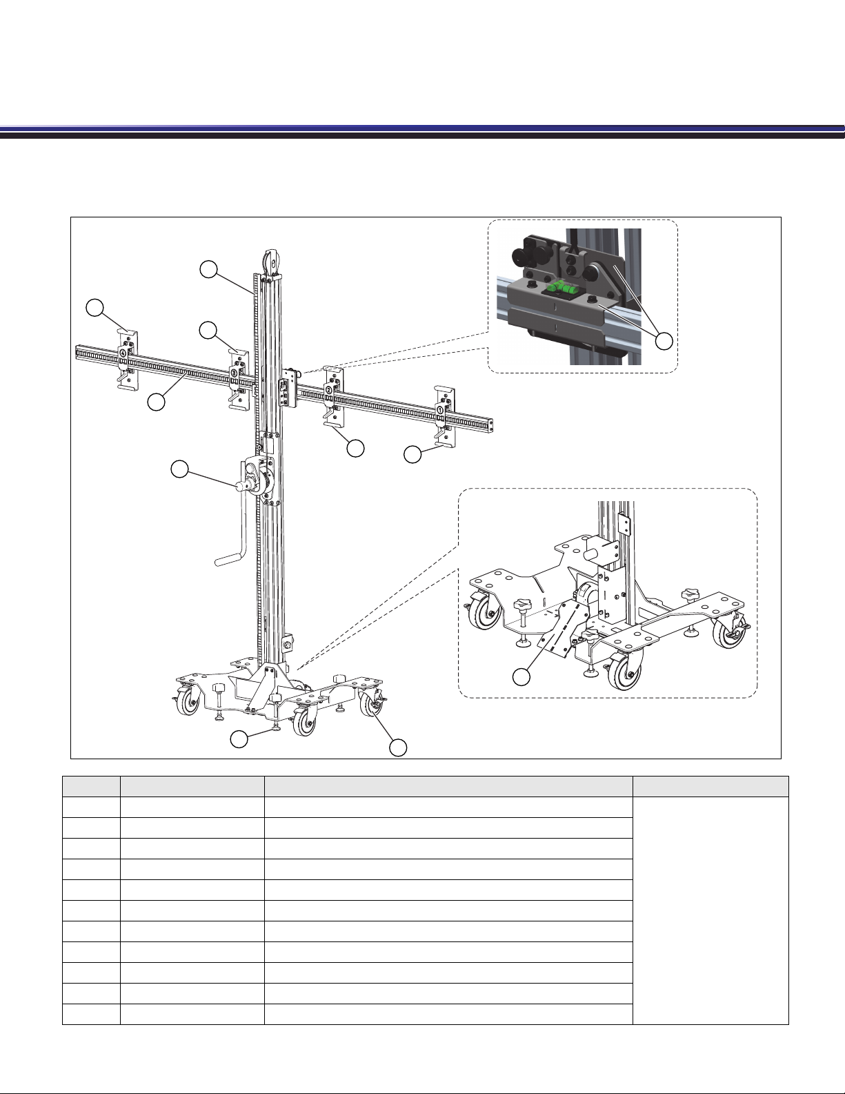
Chapter 3Service Parts
Service Kits
Item Kit Part Number Description
1EAK0366L09A Vertical Scale Service Kit
Kit Instruction Sheets
Located in Index.
2EAK0366L10A Cross Beam Pivot Service Kit
3EAK0366L07A No. 4 Target Mount Service Kit
4EAK0366L06A No. 3 Target Mount Service Kit
5EAK0366L05A No. 2 Target Mount Service Kit
6EAK0366L04A No. 1 Target Mount Service Kit
7EAK0366L08A Cross Beam Service Kit
8EAK0366L11A Winch Service Kit
9EAK0366L02A Leveling Foot Service Kit
10 EAK0366L01A Caster Service Kit
11 EAK0366L03A Front Alignment Plate Service Kit
1
9
3
4
56
7
8
10
11
2
EAZ0139L70A Rev.A 20-L-19

2
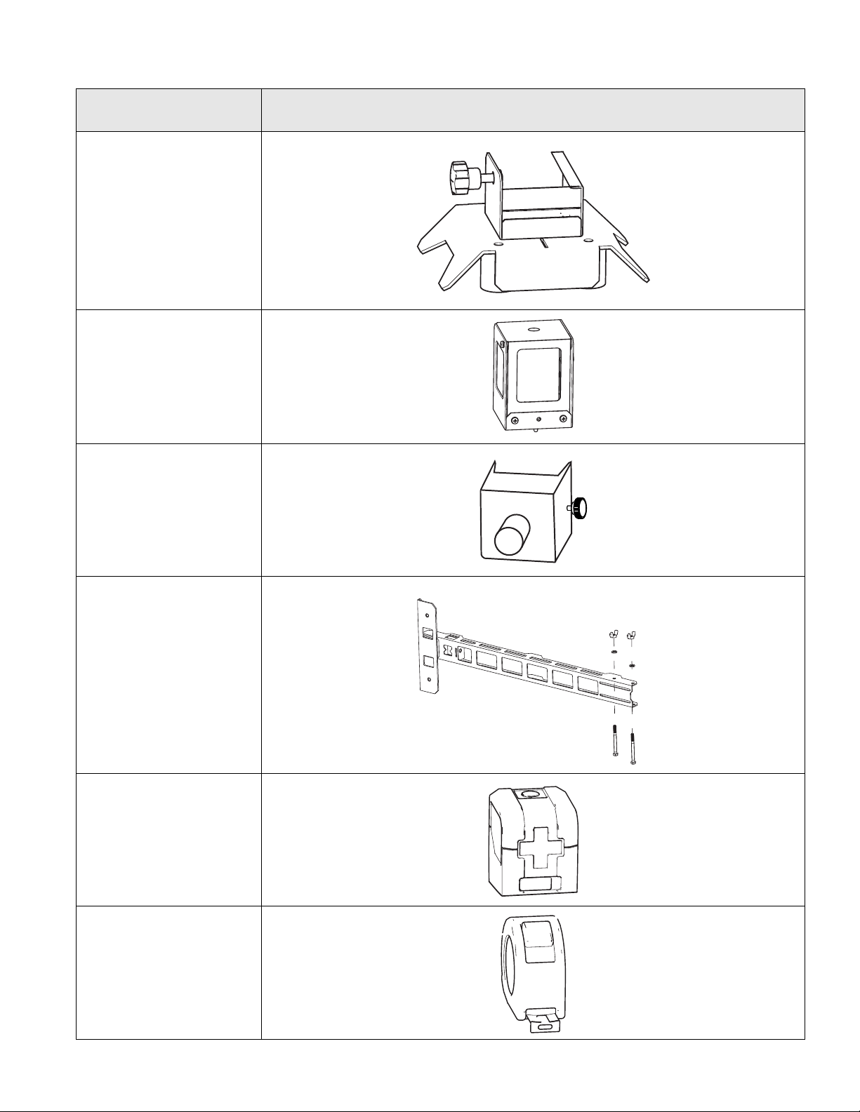
Service Parts Recalibration Fixtures and Hardware
Recalibration Fixtures and Hardware
Name / Part Number /
Qty Image
Target Thumbscrew
Pack of 12
EAK0366L12A
AS10
Alignment Fixture
EAA0496L05AR
AS11
Alignment Fixture
(use with AS10)
EAA0496L15AR
AS20
Rear Laser
Alignment Fixture
EAA0496L07AR
AS21
Rear Alignment
Fixture
EAA0496L12AR
3
Service Parts Recalibration Fixtures and Hardware
1
2
4
5
6
7
8
9
10
3
AT10
Tape Rule Stand
EAA0496L09AR
Laser Stand
EAA0496L06AR
Zero Stop
EAA0496L13AR
Honda Extension
Arm Kit
(North America)
EAA0496L04AR
Laser Unit
3-24413A
Tape Rule
1-41584A
Name / Part Number /
Qty Image
4
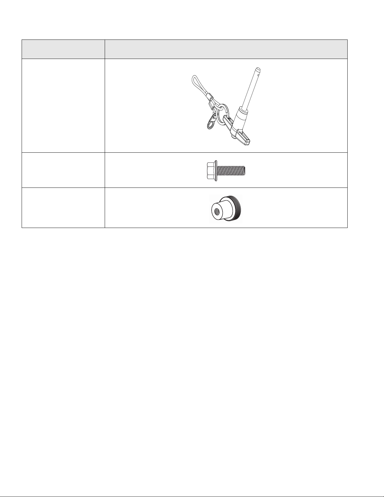
Service Parts Recalibration Fixtures and Hardware
T-Handle Quick
Lock Pin and
Lanyard
8-73437A01
Cross Beam
Pivot Bolt
1-05115A
Knurled Locking
Knob
1-42984A
Name / Part Number /
Qty Image

5
Service Parts Front Camera Targets
1
2
4
5
6
7
8
9
10
3
Front Camera Targets
**IMPORTANT**
Prior to using any of the targets referenced in this document, the user should check the applicable automotive
manufacturer’s service information to make certain that the most recently published targets are used. Do not use the
targets published in this document if the automotive manufacturer has published targets that are more recent..
Name / Part Number /
Qty Image
FIAT®
FIA-FC-01
EAK0362L18A
(Qty. 1)
HONDA® / ACURA®
HON-FC-01
EAK0362L28A
(Set - Qty. 2 Pc.)
HON-FC-02
EAK0362L11A
(Set - Qty. 3 Pc.)

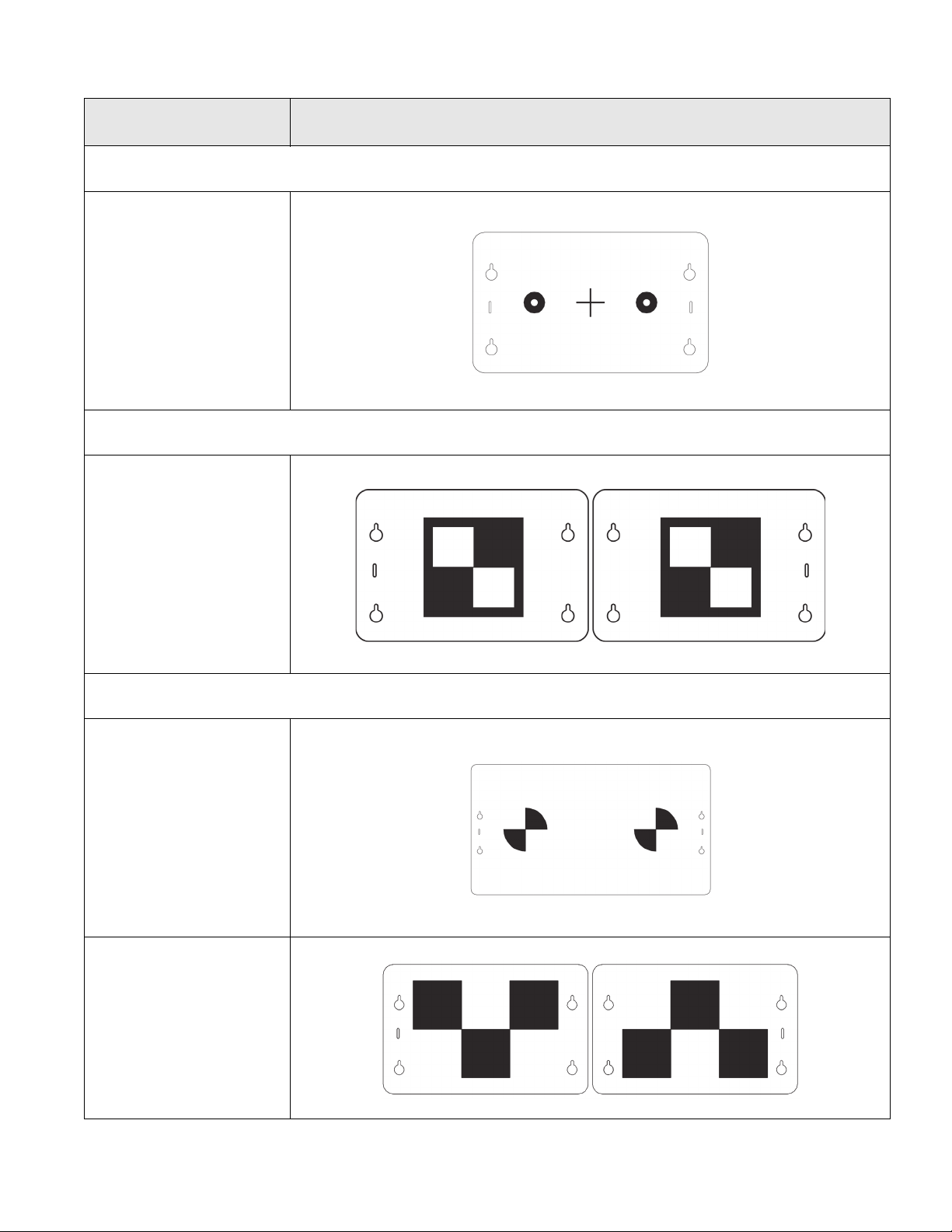
6
Service Parts Front Camera Targets
HON-FC-03
EAK0362L13A
(Qty. 1)
HYUNDAI® / KIA®
HYU-FC-01
EAK0362L29A
(Qty. 1)
MAZDA®
MAZ-FC-01
EAK0362L27A
(Qty. 1)
MAZ-FC-02
EAK0362L33A
(Set - Qty. 2 Pc.)
Name / Part Number /
Qty Image
7
Service Parts Front Camera Targets
1
2
4
5
6
7
8
9
10
3
MERCEDES-BENZ®
MB-FC-01
EAK0362L25A
(Qty. 1)
MITSUBISHI®
MIT-FC-01
EAK0362L32A
(Set - Qty. 2 Pc.)
NISSAN® / INFINITY®
NIS-FC-01
EAK0362L30A
(Qty. 1)
NIS-FC-02
EAK0362L26A
(Set - Qty. 2 Pc.)
Name / Part Number /
Qty Image

8
Service Parts Front Camera Targets
NIS-FC-03
EAK0362L20A
(Set - Qty. 2 Pc.)
TOYOTA® / LEXUS®
TOY-FC-01
EAK0362L34A
(Qty. 1)
TOY-FC-02
EAK0362L23A
(Qty. 1)
TOY-FC-03
EAK0362L24A
(Qty. 1)
Name / Part Number /
Qty Image
Table of contents


