manuals.online logo
Brands
  1. Home
  2. •
  3. Brands
  4. •
  5. JohnDow Industries
  6. •
  7. Outdoor Cart
  8. •
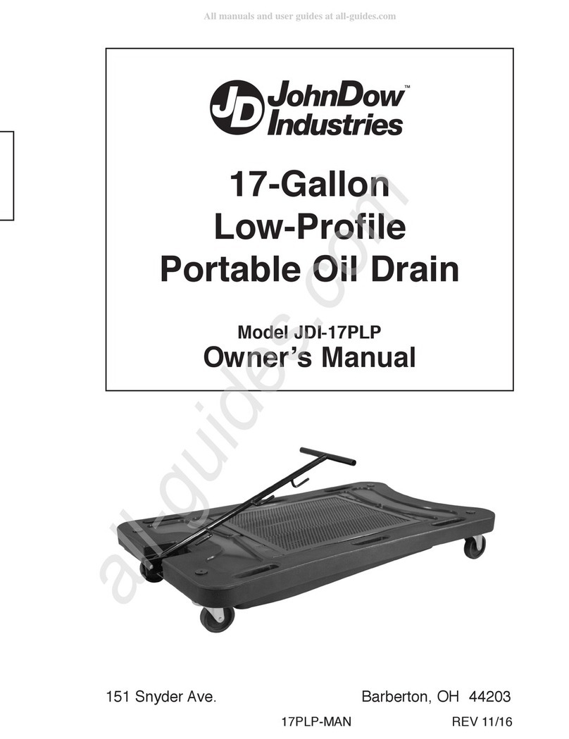
  9. JohnDow Industries JDI-LP5 User manual

JohnDow Industries JDI-LP5 User manual

25-Ga on
Low-Profi e
Portab e Oi Drain
With E ectric Evacuation Pump
Mode JDI-LP5
Owner’s Manua
™
REV 1/30/18
151 Sny er Ave. Barberton, OH 44203
For Service Assistance • Phone To Free 1-800-433-0708
OPERATOR’S MAN AL JDI-LP5
Operation:
To Fill:
1. Roll the drain under the vehicle to be serviced and drain the fluid into the drain.
To Empty:
1. Position the drain next to the used oil storage receptacle.
2. Attach the 10’ evacuation hose to the pump outlet side quick connect coupler. Make sure connection is secure.
3. Place the other end of the evacuation hose securely into the used oil receptacle.
4. Plug the electric pump into a 120V outlet. The pump will self prime and start to pump.
5. Monitor the level in the drain and unplug the pump when the drain is evacuated
.
6. When finished, disconnect the evacuation hose and position the end onto the cradle. Wrap the electrical cord onto the storage cleat.
JDI-LP5 Manual 1 30 18:Layout 1 5/9/18 9:08 AM Page 1
OPERATOR’S MAN AL JDI-LP5 OPERATOR’S MAN AL JDI-LP5
Operating and Safety Precautions:
1. Read assembly and operating instructions and instructions before use
2. Personnel should always wear proper personal protection equipment and clothing.
3. Ensure that all fittings and connections are properly tightened.
4. Oil is flammable. Keep away from heat, sparks, and open flames as an explosion will result in severe personal injury including death.
5. Monitor the fluid level when filling the drain to prevent overflow or spillage.
6. Use care when rolling the oil drain when it is full of oil to prevent splashing or spillage.
7. Periodically inspect the screen for debris that may prevent the flow of oil.
8. Always connect the evacuation hose before running pump
9. Monitor the discharge hose when evacuating the drain to prevent overflow or spillage
Product Specifications:
a. Max. Tank Capacity: 26.6 gal (100 L) c. Electrical: 120 V/ 50-60 Hz
b. Functional Capacity: 22.6 gal (85 L) d. Max. Flow Rate: 5 gpm (18.9 L/min)
Assembly
Tools and Supplies (not included)
PTFE tape 10 mm wrench 1-1⁄16” open end wrench 13mm open end wrench
11⁄16” open end wrench Pipe wrench Flat screw driver 17mm open end wrench
19mm open end wrench
Assembly Procedure:
1. Assemble M12 flat washer (15), nut (16), and hex head screw (14) to wheels (13) using
19mm socket and wrench (see Fig. 1).
2. Assemble four M10 hex head screws (9), four M10 nuts (12), and eight M10 flat washers
(10) per caster (11) using 17mm socket and wrench (see Fig. 2).
3. Wrap ¾ NPT threads on drain with PTFE tape and assemble ¾ NPT elbow (17). Tighten
using pipe wrench and position facing upward (see Fig. 3).
4. Remove eight M6 bolts (22) and pump cover (21) from rear of drain using 10mm wrench
(see Fig. 4). Mount the pump (23) and reinstall four M6 bolts with 10mm wrench.
5. Wrap ¾ NPT end of the ½ x 6-1/2 inch hose (18) with PTFE tape and thread into ¾ NPT
elbow(17). Tighten with a 1-1/16 inch wrench (see Fig. 5).
6. Wrap PTFE tape onto the ½ x 3/8 NPT hose barb fitting (20) and thread into the inside of
the pump (23). Tighten with a 11/16 wrench.
7. Place the hose clamp (19) on the ½ x 6-1/2 hose (18). Flex the hose to form a 90° arc and
slide the hose end onto the ½ x 3/8 hose barb fitting (20) on the pump (see Fig. 6).
8. Position the hose clamp and tighten with flat head screw driver.
9. Wrap PTFE tape onto ½ NPT thread end of the ½ x 5-1/2 inch outlet hose (24) and assem-
ble female quick connector fitting
10. Wrap PTFE tape onto the 3/8 NPT end of the ½ x 5-1/2 inch outlet hose (24) and thread into
pump (23). Tighten with 11/16 wrench (see Fig. 7).
11. Reinstall the pump cover (21) using four M6 bolts (22) and tighten with 10mm wrench (see
Fig. 8).
12. Wrap the electrical cord of pump on the cleat of pump cover.
13. Wrap PTFE on the ½ NPT thread of the ½ x 10’ evacuation hose and assemble to the male
quick connect fittings.
14. Assemble 4 piece handle assembly (3, 6 x2, 8) with four M8 washers (4), nuts (7), and hex
head screws (5), using 13mm socket and wrench (see Fig.9).
15. Attach handle assembly to tank with two M8 washers (4), nut (7), and hex head screw (5)
using 13mm socket and wrench
Fig. 1
Fig. 2
Fig. 3
Fig. 4
Fig. 5
Fig. 6
Fig. 9
Fig. 7 Fig. 8
2. 3.
Product Specifications:
3
8
5
4
6
7
12
11
1
13
14
21
17
22
24
23
18
2
910
19
20
15 16
22
Contents:
Item
No. Description Qty.
12 M10 Nylon - Insert Locknut 8
13 6” Wheel 2
14 M12 Hex Head Cap Screw 2
15 M12 Flat Washer 2
16 M12 Nylon - Insert Locknut 2
17 3/4” NPT Elbow 1
18 1/2” x 5-1/2” Hose with 3/4”
Fitting 1
19 1” Hose Clamp 1
20 1/2” x 3/8” NPT Hose Barb
Fitting 1
Item
No. Description Qty.
1 Tank 1
2 Screen 1
3 Handle - Top 1
4 M8 Flat Washer 4
5 M8 Hex Head Cap Screw 2
6 Handle Brace 2
7 M8 Nylon - Insert Locknut 2
8 Handle Bottom 1
9 M10 Hex Head Cap Screw 8
10 M10 Flat Washer 16
11 Front Swivel Caster 2
Item
No. Description Qty.
21 Pump Cover 1
22 M6 Hex Head Cap Screw 8
23 120V Electric Pump 1
24 1/2” x 6-1/2” Outlet Hose with
3/8” and 1/2” NPT Fitting 1
25 1/2” NPT Female uick
Connector 1
26 1/2” NPT Male uick
Connector 1
27 1/2” x 10’ Evacation Hose 1
JDI-LP5 Manual 1 30 18:Layout 1 5/9/18 9:09 AM Page 2
OPERATOR’S MAN AL JDI-LP5 OPERATOR’S MAN AL JDI-LP5
Operating and Safety Precautions:
1. Read assembly and operating instructions and instructions before use
2. Personnel should always wear proper personal protection equipment and clothing.
3. Ensure that all fittings and connections are properly tightened.
4. Oil is flammable. Keep away from heat, sparks, and open flames as an explosion will result in severe personal injury including death.
5. Monitor the fluid level when filling the drain to prevent overflow or spillage.
6. Use care when rolling the oil drain when it is full of oil to prevent splashing or spillage.
7. Periodically inspect the screen for debris that may prevent the flow of oil.
8. Always connect the evacuation hose before running pump
9. Monitor the discharge hose when evacuating the drain to prevent overflow or spillage
Product Specifications:
a. Max. Tank Capacity: 26.6 gal (100 L) c. Electrical: 120 V/ 50-60 Hz
b. Functional Capacity: 22.6 gal (85 L) d. Max. Flow Rate: 5 gpm (18.9 L/min)
Assembly
Tools and Supplies (not included)
PTFE tape 10 mm wrench 1-1⁄16” open end wrench 13mm open end wrench
11⁄16” open end wrench Pipe wrench Flat screw driver 17mm open end wrench
19mm open end wrench
Assembly Procedure:
1. Assemble M12 flat washer (15), nut (16), and hex head screw (14) to wheels (13) using
19mm socket and wrench (see Fig. 1).
2. Assemble four M10 hex head screws (9), four M10 nuts (12), and eight M10 flat washers
(10) per caster (11) using 17mm socket and wrench (see Fig. 2).
3. Wrap ¾ NPT threads on drain with PTFE tape and assemble ¾ NPT elbow (17). Tighten
using pipe wrench and position facing upward (see Fig. 3).
4. Remove eight M6 bolts (22) and pump cover (21) from rear of drain using 10mm wrench
(see Fig. 4). Mount the pump (23) and reinstall four M6 bolts with 10mm wrench.
5. Wrap ¾ NPT end of the ½ x 6-1/2 inch hose (18) with PTFE tape and thread into ¾ NPT
elbow(17). Tighten with a 1-1/16 inch wrench (see Fig. 5).
6. Wrap PTFE tape onto the ½ x 3/8 NPT hose barb fitting (20) and thread into the inside of
the pump (23). Tighten with a 11/16 wrench.
7. Place the hose clamp (19) on the ½ x 6-1/2 hose (18). Flex the hose to form a 90° arc and
slide the hose end onto the ½ x 3/8 hose barb fitting (20) on the pump (see Fig. 6).
8. Position the hose clamp and tighten with flat head screw driver.
9. Wrap PTFE tape onto ½ NPT thread end of the ½ x 5-1/2 inch outlet hose (24) and assem-
ble female quick connector fitting
10. Wrap PTFE tape onto the 3/8 NPT end of the ½ x 5-1/2 inch outlet hose (24) and thread into
pump (23). Tighten with 11/16 wrench (see Fig. 7).
11. Reinstall the pump cover (21) using four M6 bolts (22) and tighten with 10mm wrench (see
Fig. 8).
12. Wrap the electrical cord of pump on the cleat of pump cover.
13. Wrap PTFE on the ½ NPT thread of the ½ x 10’ evacuation hose and assemble to the male
quick connect fittings.
14. Assemble 4 piece handle assembly (3, 6 x2, 8) with four M8 washers (4), nuts (7), and hex
head screws (5), using 13mm socket and wrench (see Fig.9).
15. Attach handle assembly to tank with two M8 washers (4), nut (7), and hex head screw (5)
using 13mm socket and wrench
Fig. 1
Fig. 2
Fig. 3
Fig. 4
Fig. 5
Fig. 6
Fig. 9
Fig. 7 Fig. 8
2. 3.
Product Specifications:
3
8
5
4
6
7
12
11
1
13
14
21
17
22
24
23
18
2
910
19
20
15 16
22
Contents:
Item
No. Description Qty.
12 M10 Nylon - Insert Locknut 8
13 6” Wheel 2
14 M12 Hex Head Cap Screw 2
15 M12 Flat Washer 2
16 M12 Nylon - Insert Locknut 2
17 3/4” NPT Elbow 1
18 1/2” x 5-1/2” Hose with 3/4”
Fitting 1
19 1” Hose Clamp 1
20 1/2” x 3/8” NPT Hose Barb
Fitting 1
Item
No. Description Qty.
1 Tank 1
2 Screen 1
3 Handle - Top 1
4 M8 Flat Washer 4
5 M8 Hex Head Cap Screw 2
6 Handle Brace 2
7 M8 Nylon - Insert Locknut 2
8 Handle Bottom 1
9 M10 Hex Head Cap Screw 8
10 M10 Flat Washer 16
11 Front Swivel Caster 2
Item
No. Description Qty.
21 Pump Cover 1
22 M6 Hex Head Cap Screw 8
23 120V Electric Pump 1
24 1/2” x 6-1/2” Outlet Hose with
3/8” and 1/2” NPT Fitting 1
25 1/2” NPT Female uick
Connector 1
26 1/2” NPT Male uick
Connector 1
27 1/2” x 10’ Evacation Hose 1
JDI-LP5 Manual 1 30 18:Layout 1 5/9/18 9:09 AM Page 2
25-Ga on
Low-Profi e
Portab e Oi Drain
With E ectric Evacuation Pump
Mode JDI-LP5
Owner’s Manua
™
REV 1/30/18
151 Sny er Ave. Barberton, OH 44203
For Service Assistance • Phone To Free 1-800-433-0708
OPERATOR’S MAN AL JDI-LP5
Operation:
To Fill:
1. Roll the drain under the vehicle to be serviced and drain the fluid into the drain.
To Empty:
1. Position the drain next to the used oil storage receptacle.
2. Attach the 10’ evacuation hose to the pump outlet side quick connect coupler. Make sure connection is secure.
3. Place the other end of the evacuation hose securely into the used oil receptacle.
4. Plug the electric pump into a 120V outlet. The pump will self prime and start to pump.
5. Monitor the level in the drain and unplug the pump when the drain is evacuated
.
6. When finished, disconnect the evacuation hose and position the end onto the cradle. Wrap the electrical cord onto the storage cleat.
JDI-LP5 Manual 1 30 18:Layout 1 5/9/18 9:08 AM Page 1

Other JohnDow Industries Outdoor Cart manuals

JohnDow Industries FC-25PFC User manual

JohnDow Industries

JohnDow Industries FC-25PFC User manual

JohnDow Industries JDI-TT1 User manual

JohnDow Industries

JohnDow Industries JDI-TT1 User manual

JohnDow Industries JDI-TT1 User manual

JohnDow Industries

JohnDow Industries JDI-TT1 User manual

JohnDow Industries FC-25GC User manual

JohnDow Industries

JohnDow Industries FC-25GC User manual

JohnDow Industries GAS & GO GG-25PFC-D User manual

JohnDow Industries

JohnDow Industries GAS & GO GG-25PFC-D User manual

JohnDow Industries JDI-PLP17 User manual

JohnDow Industries

JohnDow Industries JDI-PLP17 User manual

JohnDow Industries JDI-17PLP User manual

JohnDow Industries

JohnDow Industries JDI-17PLP User manual

Popular Outdoor Cart manuals by other brands

Famica S-Cart manual

Famica

Famica S-Cart manual

Winsome 40826 R2 quick start guide

Winsome

Winsome 40826 R2 quick start guide

Cub Cadet 19A40036100 Operator's manual

Cub Cadet

Cub Cadet 19A40036100 Operator's manual

PROAIM CINEMA Series Assembly manual

PROAIM

PROAIM CINEMA Series Assembly manual

Oypla Leisure 4056 manual

Oypla Leisure

Oypla Leisure 4056 manual

Playmarket GO UP instructions

Playmarket

Playmarket GO UP instructions

ONKRON TS1551 user guide

ONKRON

ONKRON TS1551 user guide

Vertiflex Products SmartWorx VF52006 Assembly instructions

Vertiflex Products

Vertiflex Products SmartWorx VF52006 Assembly instructions

Forge W-KIT-1-BK-1PC installation manual

Forge

Forge W-KIT-1-BK-1PC installation manual

Expert Gardener EG-410 quick start guide

Expert Gardener

Expert Gardener EG-410 quick start guide

Universal Attachment 610-24356 user guide

Universal Attachment

Universal Attachment 610-24356 user guide

t&mMount Motor Lift Mobile manual

t&mMount

t&mMount Motor Lift Mobile manual

Opti-Med JM025-017 user manual

Opti-Med

Opti-Med JM025-017 user manual

Agri-Fab 7 cu ft. Farm/Garden Cart 45-01761 owner's manual

Agri-Fab

Agri-Fab 7 cu ft. Farm/Garden Cart 45-01761 owner's manual

Makita DCU603 instruction manual

Makita

Makita DCU603 instruction manual

Tourtecs GW3 General Notes

Tourtecs

Tourtecs GW3 General Notes

Homelite LM-16002-36 Assembly instructions and parts list

Homelite

Homelite LM-16002-36 Assembly instructions and parts list

Sport-thieme 126 4917 Operating & assembly instructions

Sport-thieme

Sport-thieme 126 4917 Operating & assembly instructions

manuals.online logo
manuals.online logoBrands
  • About & Mission
  • Contact us
  • Privacy Policy
  • Terms and Conditions

Copyright 2025 Manuals.Online. All Rights Reserved.