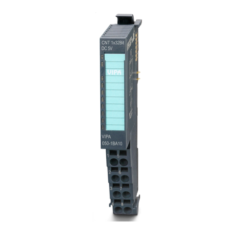
VIPA SLIO FM 050-1BB30 User manual

VIPA System SLIO
FM | 050-1BB30 | Manual
HB300E_FM | RE_050-1BB30 | Rev. 10/30
July 2010

Copyright © VIPA GmbH. All Rights Reserved.
This document contains proprietary information of VIPA and is not to be disclosed or used except in accordance with applicable
agreements.
This material is protected by the copyright laws. It may not be reproduced, distributed, or altered in any fashion by any entity (either
internal or external to VIPA), except in accordance with applicable agreements, contracts or licensing, without the express written
consent of VIPA and the business management owner of the material.
For permission to reproduce or distribute, please contact:
VIPA, Gesellschaft für Visualisierung und Prozessautomatisierung mbH
Ohmstraße 4, D-91074 Herzogenaurach, Germany
Tel.: +49 (91 32) 744 -0
Fax.: +49 9132 744 1864
http://www.vipa.de
Note
Every effort has been made to ensure that the information contained in this document was complete and accurate at the time of
publishing. Nevertheless, the authors retain the right to modify the information. This customer document describes all the hardware
units and functions known at the present time. Descriptions may be included for units which are not present at the customer site. The
exact scope of delivery is described in the respective purchase contract.
CE Conformity
Hereby, VIPA GmbH declares that the products and systems are in compliance with the essential requirements and other relevant
provisions of the following directives:
• 2004/108/EC Electromagnetic Compatibility Directive
• 2006/95/EC Low Voltage Directive
Conformity is indicated by the CE marking affixed to the product.
Conformity Information
For more information regarding CE marking and Declaration of Conformity (DoC), please contact your local VIPA customer service
organization.
Trademarks
VIPA, SLIO, System 100V, System 200V, System 300V, System 300S, System 400V, System 500S and Commander Compact are
registered trademarks of VIPA Gesellschaft für Visualisierung und Prozessautomatisierung mbH.
SPEED7 is a registered trademark of profichip GmbH.
SIMATIC, STEP, SINEC, S7-300 and S7-400 are registered trademarks of Siemens AG.
Microsoft und Windows are registered trademarks of Microsoft Inc., USA.
Portable Document Format (PDF) and Postscript are registered trademarks of Adobe Systems, Inc.
All other trademarks, logos and service or product marks specified herein are owned by their respective companies.
Information product support
Contact your local VIPA Customer Service Organization representative if you wish to report errors or questions regarding the contents
of this document. If you are unable to locate a customer service center, contact VIPA as follows:
VIPA GmbH, Ohmstraße 4, 91074 Herzogenaurach, Germany
Telefax:+49 9132 744 1204
EMail: documentation@vipa.de
Technical support
Contact your local VIPA Customer Service Organization representative if you encounter problems with the product or have questions
regarding the product. If you are unable to locate a customer service center, contact VIPA as follows:
VIPA GmbH, Ohmstraße 4, 91074 Herzogenaurach, Germany
Telephone: +49 9132 744 1150/1180 (Hotline)

Manual VIPA System SLIO Contents
HB300E - FM - RE_050-1BB30 - Rev. 10/30 i
Contents
About this manual....................................................................................1
Safety information....................................................................................2
Chapter 1 Basics and Assembly .....................................................1-1
Safety Information for Users................................................................. 1-2
System conception............................................................................... 1-3
Dimensions .......................................................................................... 1-6
Installation............................................................................................ 1-7
Wiring................................................................................................. 1-11
Trouble shooting - LEDs..................................................................... 1-14
Installation guidelines ......................................................................... 1-15
General data ...................................................................................... 1-18
Chapter 2 Hardware description .....................................................2-1
Properties............................................................................................. 2-2
Structure .............................................................................................. 2-3
Technical Data ..................................................................................... 2-5
Chapter 3 Deployment .....................................................................3-1
Fast introduction................................................................................... 3-2
In-/Output area..................................................................................... 3-4
Parameter data .................................................................................... 3-5
Counter functions ................................................................................. 3-6
Diagnostic data .................................................................................... 3-7

Contents Manual VIPA System SLIO
ii HB300E - FM - RE_050-1BB30 - Rev. 10/30

Manual VIPA System SLIO About this manual
HB300E - FM - RE_050-1BB30 - Rev. 10/30 1
About this manual
This manual describes the function module FM 050-1BB30 of the system
SLIO from VIPA. Here you may find besides of a product overview a
detailed description of the function module. You’ll receive information about
the connection and the deployment of the System SLIO module.
Chapter 1: Basics and Assembly
The focus of this chapter is on the introduction of the VIPA System SLIO.
Here you will find the information required to assemble and wire a
controller system consisting of System SLIO components.
Besides the dimensions the general technical data of System SLIO will be
found.
Chapter 2: Hardware description
In this chapter the counter module 050-1BB30 of the System SLIO is
described. Here every information about the hardware components of the
module may be found.
The technical data are at the end of the chapter.
Chapter 3: Deployment
In this chapter the deployment of the System SLIO counter module
050-1BB30 is described. Here every information required for the
deployment may be found.
Overview

About this manual Manual VIPA System SLIO
2 HB300E - FM - RE_050-1BB30 - Rev. 10/30
This manual describes the System SLIO function module 050-1BB30 from
VIPA.
It contains a description of the construction, project implementation and
usage.
The manual is targeted at users who have a background in automation
technology.
The manual consists of chapters. Every chapter provides a self-contained
description of a specific topic.
The following guides are available in the manual:
• an overall table of contents at the beginning of the manual
• an overview of the topics for every chapter
The manual is available in:
• printed form, on paper
• in electronic form as PDF-file (Adobe Acrobat Reader)
Important passages in the text are highlighted by following icons and
headings:
Danger!
Immediate or likely danger.
Personal injury is possible.
Attention!
Damages to property is likely if these warnings are not heeded.
Note!
Supplementary information and useful tips.
Objective and
contents
Target audience
Structure of the
manual
Guide to the
document
Availability
Icons
Headings

Manual VIPA System SLIO Safety information
HB300E - FM - RE_050-1BB30 - Rev. 10/30 3
Safety information
The System SLIO is constructed and produced for:
• communication and process control
• general control and automation applications
• industrial applications
• operation within the environmental conditions specified in the technical
data
• installation into a cubicle
Danger!
This device is not certified for applications in
• in explosive environments (EX-zone)
The manual must be available to all personnel in the
• project design department
• installation department
• commissioning
• operation
The following conditions must be met before using or commissioning
the components described in this manual:
• Modification to the process control system should only be carried out
when the system has been disconnected from power!
• Installation and modifications only by properly trained personnel
• The national rules and regulations of the respective country must be
satisfied (installation, safety, EMC ...)
National rules and regulations apply to the disposal of the unit!
Applications
conforming with
specifications
Documentation
Disposal

Safety information Manual VIPA System SLIO
4 HB300E - FM - RE_050-1BB30 - Rev. 10/30

Manual VIPA System SLIO Chapter 1 Basics and Assembly
HB300E - FM - RE_050-1BB30 - Rev. 10/30 1-1
Chapter 1 Basics and Assembly
The focus of this chapter is on the introduction of the VIPA System SLIO.
Here you will find the information required to assemble and wire a
controller system consisting of System SLIO components.
Besides the dimensions the general technical data of System SLIO will be
found.
Topic Page
Chapter 1 Basics and Assembly .....................................................1-1
Safety Information for Users................................................................. 1-2
System conception............................................................................... 1-3
Dimensions .......................................................................................... 1-6
Installation............................................................................................ 1-7
Wiring................................................................................................. 1-11
Trouble shooting - LEDs..................................................................... 1-14
Installation guidelines ......................................................................... 1-15
General data ...................................................................................... 1-18
Overview
Content

Chapter 1 Basics and Assembly Manual VIPA System SLIO
1-2 HB300E - FM - RE_050-1BB30 - Rev. 10/30
Safety Information for Users
VIPA modules make use of highly integrated components in MOS-
Technology. These components are extremely sensitive to over-voltages
that can occur during electrostatic discharges.
The following symbol is attached to modules that can be destroyed by
electrostatic discharges.
The Symbol is located on the module, the module rack or on packing
material and it indicates the presence of electrostatic sensitive equipment.
It is possible that electrostatic sensitive equipment is destroyed by energies
and voltages that are far less than the human threshold of perception.
These voltages can occur where persons do not discharge themselves
before handling electrostatic sensitive modules and they can damage
components thereby, causing the module to become inoperable or
unusable.
Modules that have been damaged by electrostatic discharges can fail after
a temperature change, mechanical shock or changes in the electrical load.
Only the consequent implementation of protection devices and meticulous
attention to the applicable rules and regulations for handling the respective
equipment can prevent failures of electrostatic sensitive modules.
Modules must be shipped in the original packing material.
When you are conducting measurements on electrostatic sensitive
modules you should take the following precautions:
• Floating instruments must be discharged before use.
• Instruments must be grounded.
Modifying electrostatic sensitive modules you should only use soldering
irons with grounded tips.
Attention!
Personnel and instruments should be grounded when working on
electrostatic sensitive modules.
Handling of
electrostatic
sensitive modules
Shipping of
modules
Measurements and
alterations on
electrostatic
sensitive modules

Manual VIPA System SLIO Chapter 1 Basics and Assembly
HB300E - FM - RE_050-1BB30 - Rev. 10/30 1-3
System conception
System SLIO is a modular automation system for assembly on a 35mm
mounting rail. By means of the peripheral modules with 2, 4 or 8 channels
this system may properly be adapted matching to your automation tasks.
The wiring complexity is low, because the supply of the DC 24V power
section is integrated to the backplane bus and defective modules may be
replaced with standing wiring.
By deployment of the power modules in contrasting colors within the
system, further isolated areas may be defined for the DC 24V power
section supply, respectively the electronic power supply may be extended
with 2A.
The System SLIO consists of the following components:
• Bus coupler
• Periphery modules
• Power modules
• Accessories
With a bus coupler bus interface and power
module is integrated to one casing. With the bus
interface you get access to a subordinated bus
system.
Via the integrated power module for power supply
the bus interface is supplied as well as the
electronic of the connected periphery modules.
The DC 24 power section supply for the linked
periphery modules is established via a further
connection.
By installing of up to 64 periphery modules at the
bus coupler, these are electrically connected, this
means these are assigned to the backplane bus,
the electronic modules are power supplied and
each periphery module is connected to the DC
24V power section supply.
Overview
Components
Bus coupler

Chapter 1 Basics and Assembly Manual VIPA System SLIO
1-4 HB300E - FM - RE_050-1BB30 - Rev. 10/30
Each periphery module consists of a terminal and an electronic module.
[1]
[2]
[1]
[2]
Terminal module
Electronic module
The terminal module serves to carry the electronic
module, contains the backplane bus with power supply
for the electronic, the DC 24V power section supply and
the staircase-shaped terminal for wiring.
Additionally the terminal module has a locking system
for fixing at a mounting rail.
By means of this locking system your SLIO system may
be assembled outside of your switchgear cabinet to be
later mounted there as whole system.
The functionality of a SLIO periphery module is defined
by the electronic module, which is mounted to the
terminal module by a save sliding mechanism.
With an error the defective module may be exchanged
for a functional module with standing installation.
By an integrated coding only the modules may be
plugged, which may be combined.
At the front side there are LEDs for status indication.
For simple wiring each module shows a corresponding
connection diagram at the front and at the side.
In the system SLIO the power supply is established by
power modules. These are either integrated to the bus
coupler or may be installed between the periphery
modules. Depending on the power module isolated
areas of the DC 24V power section supply may be
defined respectively the electronic power supply may be
extended with 2A.
For better recognition the color of the power modules
are contrasting to the periphery modules.
Periphery modules
Terminal module
Electronic module
Power module

Manual VIPA System SLIO Chapter 1 Basics and Assembly
HB300E - FM - RE_050-1BB30 - Rev. 10/30 1-5
The shield bus carrier serves to carry the shield bus to
connect cable shields.
Shield bus carriers, shield bus and shield fixings are not
in the scope of delivery. They are only available as
accessories.
The shield bus carrier is mounted underneath the
terminal of the terminal module.
With a flat mounting rail for adaption to a flat mounting
rail you may remove the spacer of the shield bus carrier.
With each bus coupler, to protect the backplane bus
connectors, there is a mounted bus cover in the scope
of delivery. You have to remove the bus cover of the bus
coupler before mounting a SLIO module.
For the protection of the backplane bus connector you
should always mount the bus cover at the last module of
your system again.
Accessories
Shield bus carrier
Bus cover

Chapter 1 Basics and Assembly Manual VIPA System SLIO
1-6 HB300E - FM - RE_050-1BB30 - Rev. 10/30
Dimensions
104
109
76.5 48.5
104
109
76.5
15
133
12.9
58
62 12.9
Dimensions in mm
Dimensions
bus coupler
Dimensions
periphery module
Dimensions
electronic module

Manual VIPA System SLIO Chapter 1 Basics and Assembly
HB300E - FM - RE_050-1BB30 - Rev. 10/30 1-7
Installation
There is a locking lever at the top side of the terminal module. For
mounting and de-mounting this locking lever is to turn upwards until this
engages audible.
Now the module may be pulled forward.
For mounting plug the module to the module installed before and push the
module to the mounting rail guided by the strips at the upper and lower side
of the module.
The module is fixed to the mounting rail by pushing downwards the locking
lever.
The modules may either separately be mounted to the mounting rail or as
block. Here is to be considered that each locking lever is opened.
Clack
1 2 3
For mounting between 2 modules and for the exchange of a defective
electronic module, the electronic module may be pulled forward after
pressing the unlocking lever at the lower side of the module.
For installation plug the electronic module guided by the strips at the lower
side until this engages audible to the terminal module.
1. Press
2. Pull
Clack
Functional
principle
Mounting
terminal module
Mounting
electronic
module

Chapter 1 Basics and Assembly Manual VIPA System SLIO
1-8 HB300E - FM - RE_050-1BB30 - Rev. 10/30
The modules were directly be mounted to the mounting rail and so
connected to the backplane bus and the power supply for the electronic
and power section.
Up to 64 modules may be mounted. Please consider here that the sum
current of the electronic power supply does not exceed the maximum value
of 3A. By means of the power module 007-1AB10 the current of the
electronic power supply may be expanded with 2A. More about this may be
found at "Wiring".
• Mount the mounting rail! Please consider that a clearance from the
middle of the mounting rail of at least 80mm above and 60mm below,
respectively 80mm by deployment of shield bus carriers, exist.
80mm
80mm
60mm65mm
• Start at the left side with the head module (e.g. bus coupler). For this
turn both locking lever upwards, put the head module to the mounting
rail and turn both locking lever downwards.
• Before mounting the periphery modules you have to remove the bus
cover at the right side of the Head module by pulling it forward. Keep the
cover for later mounting.
1 2
Mounting
Proceeding
Mounting
mounting rail
Mounting
Head module
(e.g. bus coupler)

Manual VIPA System SLIO Chapter 1 Basics and Assembly
HB300E - FM - RE_050-1BB30 - Rev. 10/30 1-9
• Mount the periphery modules you want.
1 2
Clack
3
• After mounting the whole system, to protect the backplane bus
connectors the bus cover may now be mounted at the last module
The shield bus carrier (available as accessory) serves to carry the shield
bus to connect cable shields. The shield bus carrier is mounted underneath
the terminal of the terminal module. With a flat mounting rail for adaption to
a flat mounting rail you may remove the spacer of the shield bus carrier.
Clack
Mounting
periphery module
Mounting the
bus cover
Mounting
shield bus carrier

Chapter 1 Basics and Assembly Manual VIPA System SLIO
1-10 HB300E - FM - RE_050-1BB30 - Rev. 10/30
With the mounting of a SLIO module respectively of a group of SLIO
modules between two modules for mounting reasons you have always to
remove the electronic module of the just mounted right module. After that it
may be plugged again.
To mount the module put it to the gap between the both modules and push
it, guided by the stripes at both sides, to the mounting rail.
12 3 4
With mounting respectively de-mounting of a module group you also have
to remove the electronic module of the just mounted right module! After
mounting it may be plugged again.
For mounting respectively de-mounting the locking lever of the modules of
the block must be turned upwards.
To mount the group of modules put them to the gap between the both
modules and push it, guided by the stripes at both sides, to the mounting
rail.
After mounting the block turn each locking lever of the modules
downwards.
Clack
Mounting
between 2
modules
1 module group
between 2 modules

Manual VIPA System SLIO Chapter 1 Basics and Assembly
HB300E - FM - RE_050-1BB30 - Rev. 10/30 1-11
Wiring
DC24V
0V
DC24V
0V
1
2
DC24V max. 10A
SysDC5V max. 3A
[1] DC 24V Power section supply I/O area
[2] DC 24V for Electronic power supply bus coupler and I/O area
Note!
Power section and electronic power section supply are internally protected
against higher voltage by fuses. The fuses are within the power module.
If one fuse released, its electronic module must be exchanged!
It is recommended to externally protect the power section supply with a fast
10A fuse and the electronic power supply with a fast 4A fuse.
After PowerON of the System SLIO the LEDs RUN respectively MF get on
so far as the sum current does not exceed 3A.
With a sum current greater than 3A the LEDs may not be activated.
Here the power module with the order number 007-1AB10 is to be placed
between the peripheral modules. More concerning this may be found at the
following page.
Standard wiring
State of the
electronic power
supply via LEDs

Chapter 1 Basics and Assembly Manual VIPA System SLIO
1-12 HB300E - FM - RE_050-1BB30 - Rev. 10/30
If the 10A for the power section supply is no longer sufficient, you may use
the power module from VIPA with the order number 007-1AB00. So you
have also the possibility to define isolated groups.
The power module with the order number 007-1AB10 is to be used if the
3A for the electronic power supply at the backplane bus is no longer
sufficient.
Additionally you get an isolated group for the DC 24V power section supply
with 10A.
By placing the power module 007-1AB10 at the following backplane bus
modules may be placed with a sum current of max. 2A. Afterwards the
power module 007-1AB10 is to be placed again.
007-1AB00
Sys DC 5V: ---
DC 24V: 10A
007-1AB00
Sys DC 5V: ---
DC 24V: 10A
DC24V
0V
DC24V
0V
DC24V max. 10A
SysDC5V max. 3A
DC24V max. 10A DC24V max. 10A
DC24V
0V
DC24V
0V
1
2
1 1
007-1AB10
Sys DC 5V: 2A
DC 24V: 10A
007-1AB10
Sys DC 5V: 2A
DC 24V: 10A
DC24V
0V
DC24V
0V
DC24V max. 10A
SysDC5V max. 3A SysDC5V max. 2A SysDC5V max. 2A
DC24V max. 10A DC24V max. 10A
DC24V
0V
DC24V
0V
1
2
1 1
DC24V
0V
3DC24V
0V
3
[1] DC 24V Power section supply I/O area (max. 10A)
[2] DC 24V for Electronic power supply bus coupler and I/O area
[3] DC 24V for Electronic power supply I/O area
Deployment of the
power modules
Power module
007-1AB00
Power module
007-1AB10
Table of contents
Other VIPA Control Unit manuals

VIPA
VIPA SLIO FM 050-1BB00 User manual

VIPA
VIPA IM Series User manual

VIPA
VIPA TM-E 900-1E640 User manual

VIPA
VIPA System 300S IM 353-1DP01 User manual

VIPA
VIPA System 200V Series User manual

VIPA
VIPA 134-4EE00 User manual

VIPA
VIPA 2 SLIO System IM 053DP User manual

VIPA
VIPA TP 107-CL User manual

VIPA
VIPA System 200V PS User manual

VIPA
VIPA TM-E 900-1E660 User manual

VIPA
VIPA System 200V Series User manual

VIPA
VIPA 900-2H611 User manual

VIPA
VIPA SLIO IM 053-1DN00 User manual

VIPA
VIPA System SLIO IM 053DN User manual

VIPA
VIPA System 300S User manual

VIPA
VIPA SLIO Series User manual

VIPA
VIPA CPU 013C User manual

VIPA
VIPA IM 306-1LZ00 User manual

VIPA
VIPA TM-E 900-1E650 User manual

VIPA
VIPA System 300S User manual