manuals.online logo
Brands
  1. Home
  2. •
  3. Brands
  4. •
  5. Johnson Controls
  6. •
  7. Controllers
  8. •
  9. Johnson Controls EDA-8102 Assembly instructions

Johnson Controls EDA-8102 Assembly instructions

Installation Sheet
Issue Date 0392
1
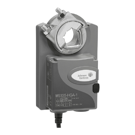
1. EDA-8102-1100 Electric Damper Actuator with counterclockwise
spring return, or
EDA-8102-1101 Electric Damper Actuator with clockwise spring
return
2. Two #10 mounting screws
3. Two isolator grommets
ςscrewdriver, flat blade, 1/4 to 5/16 inch and 1/8 inch tips
ςdrill, 5/32 inch (4 mm) drill bit, 1-1/4 inch hole saw
ςadjustable wrench
ςpliers
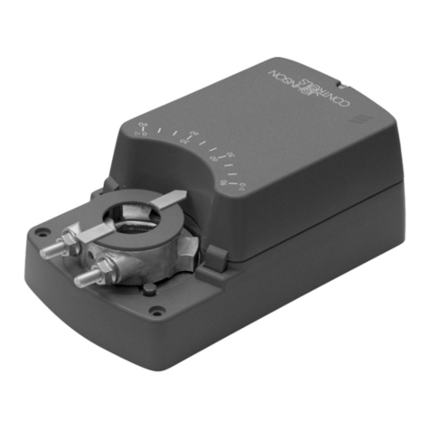
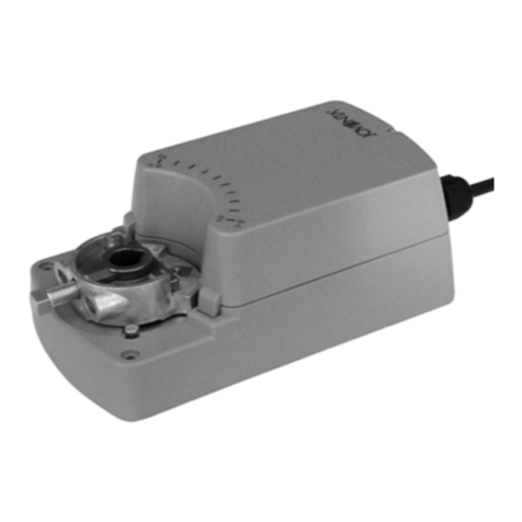
Figure 1: Electric Damper Actuator
1. Compatibility and torque:
ςuse on dampers having 10 to 12 mm (0.394 to 0.472 inch) square
or 7/16 to 1/2 inch (11 to 12.5 mm) round shafts
ςcompatible with Johnson Controls D-1300 Blade Dampers
ςdelivers 100 in.lb of stall torque
2. Mounting requirements:
ςmounts in any orientation
ςduct or wall must be 16 gauge (0.06 inch or 1.5 mm) or thicker
Note: Order the Universal Mounting Bracket (D-3153-105) to mount on
duct or wall less than 16 gauge.
EDA-8102 Electric Damper Actuator
Kit Includes
Tools Required
Installation
Overview
EDA-8102 Electric Damper Actuator
1. Follow NEC and local electrical codes.
2. Disconnect all power supplies.
3. Observe ranges and limitations for individual model.
4. Do not install the actuator in applications where its failure could result
in personal injury and/or loss of property.
5. Do not install if explosive vapors, corrosive vapors, or escaping gases
will be present.
6. Add protective control devices as needed to prevent undesirable
system failure modes.
For#10 Mounting
Screw(6places)
2.33
(59)
2x1.50
2x0.75
6.94
(235)
8.78
(223)
9.26
(235)
4.65
(118)
Figure 2: Top View Dimension inches
mm
Mounting Caution
Pre-Mounting
EDA-8102 Electric Damper Actuator 3
4.34
(110)
6 in. min*
(3x 0.875)
for 1/2 in. conduit
Rubber Grommet
(2 Required)
* Six inch minimum required for cover removal, field wiring, and field adjustments.
Figure 3: End View Dimension inches
mm
Note: Before starting the job, obtain the damper installation information
to use as a reference when mounting the actuator.
1. Locate the preferred driving blade on the damper.
2. Cut a 1-1/4 inch (32 mm) hole in the duct or wall over the driving
blade pin.
3. Attach the drive pin extension to the drive pin and secure using the
clip provided.
4. Firmly grasp the drive pin extension with a pliers and manually close
the damper blades.
RetainerClip
Drive PinExtension
Figure 4: Rotation.
5. Note which direction closes the damper, clockwise (CW) or
counterclockwise (CCW).
EDA-8102 Electric Damper Actuator
Figure 5: Removing Cover
6. Insert a screwdriver under the edge of the plastic cover to gently pry
off the cover. See Figure 5.
7. Verify the mode of operation for the proper model number from
Table 1.
Table 1: Operation Modes
Product Code
No. Drive
Type Travel
Time Spring
Return
EDA-8102-1100 proportional 180 second counterclockwise
EDA-8102-1101 proportional 180 second clockwise
Note: The actuator can be mounted in any orientation.
1. Position the actuator onto the drive pin extension so that the actuator
sits against the duct.
2. Use of the actuator’s center mounting slots with the isolation
grommets is the preferred mounting arrangement. If the duct or wall
is less than 16 gauge (0.06 inch or 1.5 mm), order and use the
Universal Mounting Bracket (D-3153-105).
Note: Because of eccentric motion of the actuator that occurs when using
shafts smaller than 10 mm (0.394 inch) square or 1/2 inch
(12.5 mm) round, use of the isolation grommets in the center
mounting slot is required.
3. Mark the location of the actuator's top and bottom mounting slots on
the duct or wall.
4. Remove the actuator and set aside.
5. Drill 5/32 inch (4 mm) holes in the duct or wall at the marked
locations.
Mounting
EDA-8102 Electric Damper Actuator 5
6. Slide the actuator onto the drive pin extension.
7. Secure the actuator to the wall or duct with the screws and insulators
included in the kit.
8. Tighten the two square-head screws on the actuator coupler.
Note: The cover should remain off until the wiring is completed.
!
CAUTION: Disconnect all power before wiring the actuator to
avoid electrical shock or damaging the equipment.
Conduit Opening Opening Covers
Figure 6: Conduit Openings
1. Insert the leads from the controller through one of the three openings.
2. Install the black plugs in the other two conduit openings. See
Figure 6.
InputVoltage
Common
24 VACInputPower
+15 VOutputSupply
Slidewire
AuxiliaryInput
ACCOMIN
+15
+1
AUXIN
TB1
TB2
Figure 7: Wiring Connections
3. Connect the leads to Terminal Block 1 (TB1) as shown in Figure 7.
Wiring
EDA-8102 Electric Damper Actuator
TB1
TB2
I
V
W2
DCW
DCCW
W1
Figure 8: Jumper Locations
4. Set jumper at location W2 to match the control signal that will be
used. Jumper settings are defined in Table 2 below and shown in
Figure 8.
Table 2: Jumper Settings
Operating Mode W2 Jumper Setting
Voltage V
Current I
Slidewire V
Note: The EDA-8102 is factory set for 90° of rotation and a voltage
control signal of 1 to 9 VDC. To change these settings, see the
section Changing Rotation To Less Than 90° or the appropriate
signal calibration.
1. Apply power to the unit.
2. Refer to the controller's manual for directions on checking out a newly
installed device.
3. Use the controller to drive the actuator fully clockwise and
counterclockwise.
4. Verify that the damper blades fully open and close.
5. Install the plastic cover.
Checkout
Procedure
EDA-8102 Electric Damper Actuator 7
The EDA-8102 is factory set for 90° of rotation and a control signal of 1
to 9 VDC. If the amount of rotation or the control signal must be changed
from factory settings, use the following procedures. Refer to Figure 7 for
the location of the potentiometer and terminal blocks in the procedures.
Figure 9: Rotation Setting
1. Verify jumper W2 is set to the voltage (V) position.
2. Verify jumper W1 is set in the desired position:
DCW for clockwise driven rotation.
DCCW for counterclockwise driven rotation.
Note: Spring return direction is NOT reversible.
3. Turn the offset potentiometer (R39) to its mid-position.
4. Turn the span potentiometer (R35) fully counterclockwise.
5. Turn the CCW potentiometer (R36) fully clockwise.
6. Connect a jumper from terminal IN (TB1) to terminal +15 (TB2) as
shown in Figure 9. The actuator rotates until the end stop is reached.
7. Slowly adjust the stroke potentiometer (R37) until the actuator rotates
to the desired end stop position.
8. Remove the jumper between terminal IN and +15.
Field Adjustments
Changing Rotation
to Less Than 90°
Span
(R35)CCW
(R36)
Stroke
(R37)Offset
(R39)
TB1
TB2
I
V
W2
AC
COM
IN
+15
+1
AUXIN
TB1TB2
DCW
DCCW
W1
EDA-8102 Electric Damper Actuator
AC
COM
IN+15 +1
AUXI
N
TB1TB2
Figure 10: End Stop Connection
9. Connect terminal IN to COM (TB1) as shown in Figure 10. The
actuator will rotate until the end stop is reached.
10. Slowly adjust the CCW potentiometer (R36) until the actuator rotates
to the desired position.
11. Remove the connection between terminals IN and COM (TB1).
Note: Calibration of offset and span is required after changing rotation.
Depending on controller application, proceed with the appropriate
calibration procedure.
EDA-8102 Electric Damper Actuator 9
Span
(R35)
CCW
(R36)
Stroke
(R37) Offset
(R39)
TB1TB2
I
V
W2
0 to 15 VDC
Input
Common
Figure 11: Voltage Mode Connection
1. Verify that jumper W2 is set to the voltage (V) position.
2. Turn the span potentiometer (R35) fully clockwise.
3. Connect the input voltage (0 to 15 VDC) between terminals IN (+) and
COM (-) on TB1.
4. Apply the starting voltage.
5. Adjust the offset potentiometer (R39) until the actuator just begins to
move.
6. Apply the full span voltage.
7. Adjust the span potentiometer (R35) until the actuator reaches its
desired limit.
8. Remove external connections and install the cover.
Voltage Mode
Calibration
EDA-8102 Electric Damper Actuator
Span
(R35)
CCW
(R36)
Stroke
(R37) Offset
(R39)
TB1
TB2
I
V
W2
0 to 20 mA
Input
Common
Figure 12: Current Mode Connection
1. Verify that jumper W2 is set to the current (I) position.
2. Turn the span potentiometer (R35) fully clockwise.
3. Connect the input current (0 to 20 mA) to terminals AUXIN (+) on
TB2 and COM (-) on TB1.
4. Apply the starting current.
5. Adjust the offset potentiometer (R39) until the actuator just begins to
move.
6. Apply full current.
7. Adjust the span potentiometer (R35) until the actuator reaches its
desired limit.
8. Remove external connections and install the cover.
Current Mode
Calibration
EDA-8102 Electric Damper Actuator 11
Span
(R35)
CCW
(R36)
Stroke
(R37) Offset
(R39)
TB1
TB2
I
V
W2
Figure 13: Slidewire Connection
1. Turn the span potentiometer (R35) fully clockwise.
2. Connect the ends of the slidewire potentiometer to the +1V and COM
terminals on TB1.
3. Connect the wiper of the slidewire potentiometer to the AUXIN
terminal on TB2.
4. With the slidewire at its minimum position, adjust the offset
potentiometer (R39) until the actuator just begins to move.
5. With the slidewire at its maximum position, adjust span potentiometer
(R35) until the actuator reaches desired limit.
6. Remove external connections and install the cover.
The EDA-8102 is not field repairable. For a replacement, contact the
nearest Johnson Controls branch office or your wholesale distributor.
Slidewire
Calibration
Field Replacement
EDA-8102 Electric Damper Actuator
Notes
Controls Group
507 E. Michigan Street
P.O. Box 423
Milwaukee, WI 53201

Other manuals for EDA-8102

1

Other Johnson Controls Controllers manuals
Johnson Controls FX-PCV1930 User manual

Johnson Controls

Johnson Controls FX-PCV1930 User manual

Johnson Controls VMA 1400 Series User manual

Johnson Controls

Johnson Controls VMA 1400 Series User manual

Johnson Controls VA-8122 Service manual

Johnson Controls

Johnson Controls VA-8122 Service manual

Johnson Controls M100G User manual

Johnson Controls

Johnson Controls M100G User manual

Johnson Controls M9310 Series User manual

Johnson Controls

Johnson Controls M9310 Series User manual

Johnson Controls VA7800 Series User manual

Johnson Controls

Johnson Controls VA7800 Series User manual

Johnson Controls NXA-VAV-01 User manual

Johnson Controls

Johnson Controls NXA-VAV-01 User manual

Johnson Controls VA9104-AGA-1S User manual

Johnson Controls

Johnson Controls VA9104-AGA-1S User manual

Johnson Controls VMA18 Series User manual

Johnson Controls

Johnson Controls VMA18 Series User manual

Johnson Controls VA7820-GG-1 Series User manual

Johnson Controls

Johnson Controls VA7820-GG-1 Series User manual

Johnson Controls M9316-A Z Series User manual
Johnson Controls

Johnson Controls M9316-A Z Series User manual

Johnson Controls LP-FX2211T-0 User manual

Johnson Controls

Johnson Controls LP-FX2211T-0 User manual

Johnson Controls FAC2611-0U User manual

Johnson Controls

Johnson Controls FAC2611-0U User manual

Johnson Controls FEC25 User manual

Johnson Controls

Johnson Controls FEC25 User manual

Johnson Controls Metasys MS-FEU1610-0U User manual

Johnson Controls

Johnson Controls Metasys MS-FEU1610-0U User manual

Johnson Controls SE-SPU101 Series User manual

Johnson Controls

Johnson Controls SE-SPU101 Series User manual

Johnson Controls F4-CV Series User manual

Johnson Controls

Johnson Controls F4-CV Series User manual

Johnson Controls ER54 User manual

Johnson Controls

Johnson Controls ER54 User manual

Johnson Controls FX-PCG26 User manual

Johnson Controls

Johnson Controls FX-PCG26 User manual

Johnson Controls PENN P70 Series User manual

Johnson Controls

Johnson Controls PENN P70 Series User manual

Johnson Controls LP-NRM653-000C User manual

Johnson Controls

Johnson Controls LP-NRM653-000C User manual

Johnson Controls P2000 Manual

Johnson Controls

Johnson Controls P2000 Manual

Johnson Controls FlexSys CB2 User manual

Johnson Controls

Johnson Controls FlexSys CB2 User manual

Johnson Controls VA-9070 Series Service manual

Johnson Controls

Johnson Controls VA-9070 Series Service manual

Popular Controllers manuals by other brands

NPM PPCI7443 user guide

NPM

NPM PPCI7443 user guide

Honeywell TheraPro HR90 owner's guide

Honeywell

Honeywell TheraPro HR90 owner's guide

Jflow controls JFER Series manual

Jflow controls

Jflow controls JFER Series manual

Doepke DFA operating instructions

Doepke

Doepke DFA operating instructions

National Instruments NI PXI-8104 installation guide

National Instruments

National Instruments NI PXI-8104 installation guide

TMS Lite High Current Series user manual

TMS Lite

TMS Lite High Current Series user manual

Basler SSR 32-12 instruction manual

Basler

Basler SSR 32-12 instruction manual

Simrad NSO evo3S MPU installation manual

Simrad

Simrad NSO evo3S MPU installation manual

Gefen EXT-CU-LAN user manual

Gefen

Gefen EXT-CU-LAN user manual

Heatcraft Refrigeration Products 25001501 Installation & operating instructions

Heatcraft Refrigeration Products

Heatcraft Refrigeration Products 25001501 Installation & operating instructions

M2M enginko MCF-LW13IO operating manual

M2M

M2M enginko MCF-LW13IO operating manual

Moeller PS 4-300 Series Hardware and engineering

Moeller

Moeller PS 4-300 Series Hardware and engineering

Martin M6 Series Guide

Martin

Martin M6 Series Guide

Siemens SIMOTION P320-4 E manual

Siemens

Siemens SIMOTION P320-4 E manual

LSIS XBF-AD04A user manual

LSIS

LSIS XBF-AD04A user manual

Vaughn EC installation manual

Vaughn

Vaughn EC installation manual

Nice Max Installation and use instructions and warnings

Nice

Nice Max Installation and use instructions and warnings

Controls C3M-2514-AS product manual

Controls

Controls C3M-2514-AS product manual

manuals.online logo
manuals.online logoBrands
  • About & Mission
  • Contact us
  • Privacy Policy
  • Terms and Conditions

Copyright 2025 Manuals.Online. All Rights Reserved.