Johnson Controls RF-2000 User manual

RF-2000 Round Fire Damper Installation Instructions 1
Refer to the QuickLIT Web site for the most up-to-date version of this document.
Applications
The RF-2000 round fire damper is designed to operate
with blade running horizontally. Dampers can be
vertically or horizontally installed with the leading edge
of the closed blade within the wall or floor.
To ensure optimum operation and performance, the
damper must be installed so it is round and free from
raking. Do not compress or stretch the damper frame
into the duct or opening.
•Mounting - Vertical or Horizontal.
•Minimum UL Classified Size - 6 in. (152 mm)
diameter.
•Maximum UL Classified Size - 24 in. (610 mm)
diameter.
Installation
Notes
Use the following notes as guidelines when installing
this product.
1. Opening Clearance: A square opening in wood or
metal stud walls or masonry walls and floors shall
be a minimum of 1 in. (25 mm) and a maximum of
2-1/2 in. (64 mm) larger than the damper diameter.
A round opening in masonry walls or floors shall
be a minimum of 1 in. (25 mm) and a maximum of
2-1/2 in. (64 mm) larger than the damper diameter.
2. Damper Sleeve: The sleeve is integral to the
damper and shall be equal to or heavier than the
gauge of the duct as described in National Fire
Protection Association (NFPA) standard NFPA90A
and as defined by the appropriate Sheet Metal and
Air Conditioning Contractors’ National Association
(SMACNA) duct construction standard.
3. Retaining Cinch Plates: Place retaining cinch
plates around the damper sleeve and cinch against
the sleeve with the screw provided on the cinching
device (see Figure 1). The plates are designed to
grab and hold the sleeve while mounting flush
against the wall or floor, retaining the damper
securely in the opening. The plates must overlap
the opening a minimum of 1/2 in. (13 mm).
Fasten the cinch plates to the wall or floor
according to the following:
• Masonry Wall – Cinch plate required on only
one side of the wall fastened to the wall with a
minimum of 1-1/4 in. (32 mm) #10 masonry
screw.
• Masonry Floor – Cinch plate required on both
sides of the floor fastened to the floor with a
minimum of 1-1/4 in. (32 mm) #10 masonry
screw.
• Metal Stud Wall – Cinch plate required on only
one side of the wall fastened to the wall by
engaging the metal stud a minimum of
1/2 in. (13 mm) with a #10 screw.
Figure 1: Retaining Cinch Plate Dimensions,
in. (mm)
RF-2000 Round Fire Damper
Installation Instructions Part No. 44-1121-32, Rev. C
Issued March 2016
44- 1121- 32, Rev. C

RF-2000 Round Fire Damper Installation Instructions2
• Wood Stud Wall – Cinch plate required on both
sides of the wall fastened to the wall by
engaging the wood stud a minimum of
1-1/2 in. (38 mm) with a #10 screw.
4. Damper Orientation: The leading edge of the
blade in the closed position must be within the
plane of the wall. Vertical installation is illustrated
and horizontal is similar. (See Figure 3 through
Figure 6.) The damper may be installed with up to
a 30 degree variance of the axle being horizontal.
The damper is approved with airflow in any
direction.
5. Duct/Sleeve Connections: Round breakaway
connections must be used. Either a 4 in. (102 mm)
wide draw band or #10 sheet metal screws spaced
equally around the circumference of the ducts as
follows:
• duct diameters of 22 in. (559 mm) and smaller
– three screws
• duct diameters over 22 in. (559 mm) to 24 in.
(610 mm) – five screws
Note: When optional sealing of these joints is
desired, the following sealants may be applied in
accordance with the sealant manufacturer's
instructions:
• Hardcast, Inc. – Iron-Grip™ 601 sealant
• Precision - PA2084T
• ECO Duct Seal 44-52
• Design Polmerics - DP1010
Note: Install the damper so that it is square and free
from raking. Compressing or stretching the damper
frame into the duct or opening may result in failed
operation and will void the warranty.
6. Optional Sealant of Dampers in Fire Rated Wall
or Floor Openings: Following the sealant
manufacturer's directions, remove dirt, grease, and
moisture from the surface to be sealed. Apply a
continuous bead of sealant to the location
applicable to your specific installation.
Approved sealant or fire stop materials:
• Dow Corning® - 999A, Silastic 732RTV
• GE® - RTV 108
• Hilti Corporation - FS-One
• 3M® - #M-CP 25WB+
• Specified Technologies, Inc. - SpecSeal®
Series SSS or LCI
• John Manville International, Inc. - Firetemp™
CI
• Rectorseal - Metacaulk 1000, Metacaulk 350i,
Biostop 500+ or Biostop 350i
Do not apply sealant within the required expansion
gap between the damper and the fire rated wall or
floor.
Press the surface of the sealant in place to dispel
any air. Allow sealant to set up and become tack-
free before operating the damper.
!
WARNING: Risk of Personal Injury.
Do not place cinch plates in the groove. If
the cinch plates are in the groove, the
damper is not properly secured. An
insecure damper may dislodge and fall,
which may result in severe personal
injury or death.
AVERTISSEMENT : Risque de
blessure.
Ne pas placer les plaques de retenue
dans la rainure. Si les plaques de retenue
se trouvent dans la rainure, le registre
coupe-feu n'est pas correctement fixé.
Il pourrait alors sortir de son logement et
de tomber, ce qui risque de provoquer
des blessures graves, voire mortelles.
Figure 2: Blade Orientation
IMPORTANT: Do not lift the damper using the
blades or actuators. Lift or handle the damper using
the frame or sleeve. Handling or lifting the damper
by the blades or actuator may damage the damper
and will void the warranty. Do not compress or
stretch the damper frame into the duct or opening.
IMPORTANT: Examine each smoke damper on a
regular basis to ensure it is not rusted or blocked. In
addition, test each smoke damper annually or semi-
annually, depending on the application, and
according to the National Fire Protection Association
(NFPA) standards, to ensure it will perform as
intended. Exercise care to ensure that such tests
are performed safely and do not cause system
damage.
RF-2000 Round Fire Damper Installation Instructions 3
Note: If opening size allows for angle on one side
only, then sealant shall be applied on only angle side.
Nothing is required on non-angle side.
Installation Diagrams
Figure 3 and Figure 4 illustrate installation in
1 and 2 hour rated masonry floors and ceilings or walls.
Note: Masonry walls require retaining cinch plates on
only one side of the wall, as shown. Floors require
retaining cinch plates on both sides of the floor.
Figure 5 and Figure 6 illustrate installation within
square openings in metal or wood stud framing
incorporating 1 and 2 hour rated drywall partitions.
Figure 3: Masonry Installation, 3 Dimensional
(3D) view
Figure 4: Masonry Installation, Side View
Figure 5: Metal Stud Installation, 3D view

RF-2000 Round Fire Damper Installation Instructions4
Screws must penetrate wood or metal studs.
Metal stud walls require retaining cinch plates on only
one side of the wall. Wood stud walls require retaining
cinch plates on both sides of the wall.
Recommended Framing for Openings in Wood
and Metal Stud Walls
1. Frame wall openings as shown in Figure 7 and
Figure 9.
2. Double vertical studs are not required for openings
36 in. wide x 36 in. high (914 mm x 914 mm) or
smaller.
3. All construction and fasteners must meet the
requirements of the appropriate wall design for
local, regional, and national codes.
4. Consult the authority having jurisdiction for other
acceptable framing methods.
Figure 6: Wood & Metal Stud Walls, Side View
Figure 7: Wooden Stud Wall Framing
Dimensions, in. (mm)
Figure 8: Wood Stud Construction

Published in U.S.A. www.johnsoncontrols.com
RF-2000 Round Fire Damper Installation Instructions 5
Metasys® and Johnson Controls® are registered trademarks of Johnson Controls, Inc.
All other marks herein are the marks of their respective owners. © 2016 Johnson Controls, Inc.
Building Efficiency
507 E. Michigan Street, Milwaukee, WI 53202
Figure 9: Metal Stud Wall Framing Dimension,
in. (mm)
Figure 10: Metal Stud Construction
European Single Point of Contact: NA/SA Single Point of Contact: APAC Single Point of Contact:
JOHNSON CONTROLS
WESTENDHOF 3
45143 ESSEN
GERMANY
JOHNSON CONTROLS
507 E MICHIGAN ST
MILWAUKEE WI 53202
USA
JOHNSON CONTROLS
C/O CONTROLS PRODUCT MANAGEMENT
NO. 22 BLOCK D NEW DISTRICT
WUXI JIANGSU PROVINCE 214142
CHINA
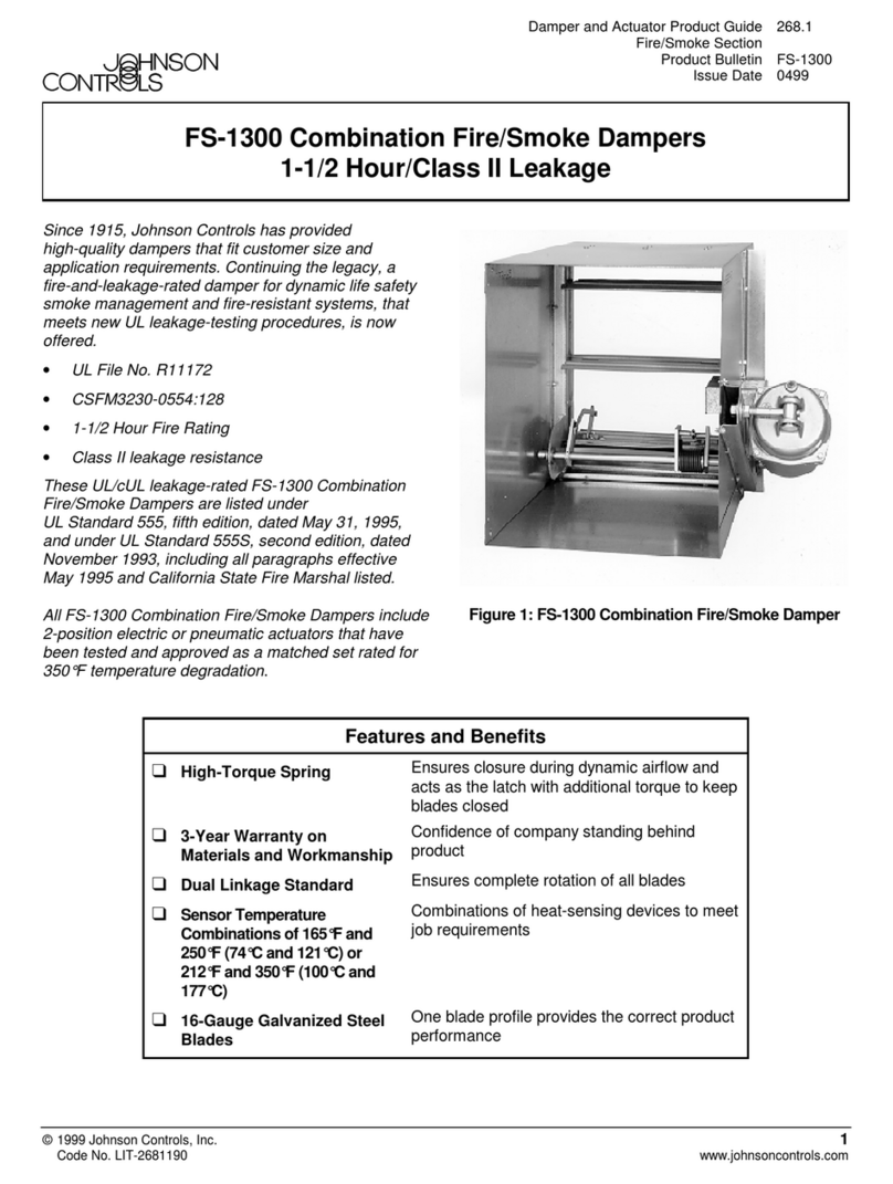
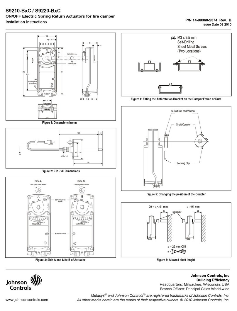
Other Johnson Controls Fire And Smoke Damper manuals

Johnson Controls
Johnson Controls S9210-BC Series User manual

Johnson Controls
Johnson Controls YORK ACTIVA 100 User manual

Johnson Controls
Johnson Controls FS-1300 User manual

Johnson Controls
Johnson Controls FD-1600 User manual

Johnson Controls
Johnson Controls BD-1300 User manual

Johnson Controls
Johnson Controls FD-1300 User manual
Popular Fire And Smoke Damper manuals by other brands

System air
System air fantech Pro 150 Installation, operation and maintenance instructions

actionair
actionair CSS Installation

Honeywell Home
Honeywell Home TrueZONE Bypass installation instructions

Komfovent
Komfovent UVS 60 H Installation instruction

SMAY
SMAY KWP-O-E-EX installation manual

LUCOMA
LUCOMA WSG-H3 Installation, operation and maintenance instructions