Ruskin actionair ES Series Operating instructions

Ruskin Air Management Limited
ES series
AIR CONTROL DAMPERS.
OPERATING AND MAINTENANCE MANUALS.
1.0 INTRODUCTION.
1.1 This manual covers series ES35, ES36,& ES50 Air Control Dampers and
should always be followed. Any deviation from this manual should always
be agreed with the manufacturer Actionair.
1.2 The ES series Air Control Dampers are designed to control airflows in
ducts, wall, ceilings and floors. The product offers numerous control
options and features, as required and specified by contractors, local fire
and or hospital authorities and consultants.
1.3 There are four casing variants: Flanged, square/rectangular, Spigot
square/rectangular, Circular and Flat oval.
1.4 All dampers are manufactured in compliance with the company’s quality
control and quality assurance procedures.
2.0 Description and Operation.
2.1 The E35 and 36 series Air Control Dampers have galvanised triple V blade
profile that operate through an opposed blade linkage system within a 1.2
thick galvanised casing.
2.2 The ES0 series Air Control Dampers have Aerofoil Aluminium blades that
operate through an opposed blade linkage system within a 1.2 thick
galvanised casing

2.3 The Linkage will provide the blade pivoting system to open and close the
blades through a rotation of 90 degrees. Refer to the ES catalogue for the
max operating parameters.
2.4 The ES damper can be operated by a manual quadrant or via a ∅½drive
spindle for motorisation by Actionair or others.
3.0 Installation Instructions.
3.1 Please ensure that the fixing framework and the ES damper flanges are
carefully matched when assembled together.
3.2 Ensure before installation that any wooden battens or packaging supplied
for transit strengthening purposes are removed. Failure to carry out this
procedure could result in permanent damage to the unit.
3.3 Before installation, the damper should be inspected to ensure that it has not
been damaged and is in good condition following transportation.
3.4 Please ensure that the damper frame and blades are free of any foreign
matter and that the assembly is not distorted in any manner and without
any dents and surface damage that could restrict blade movement.
3.5 Check that the dampers are operating correctly before carrying out
installation.
3.6 Flanged dampers when installed must be square and flat to avoid
additional torque being generated when opening and closing.
3.7 ES series dampers should not be installed with blades in the vertical
position.
3.8 Check that the dampers are operating correctly when dampers have been
installed.
4.0 Operation.
4.1 The ES series Air control damper is primarily designed for use in the
ductwork systems and can be used behind louver sets to control the
airflow. On the system being balanced during commissioning operations,
manual dampers can be locked in position by tightening the wing nut.
When dampers fitted with an actuator either by Actionair or by others you
should check the actuator operating instructions before attempting to rotate
the drive shaft when no power is available.
4.2 When actuators are fitted by others the extended drive shaft should be
fixed to the ‘F’ drive nearest centre of the damper. The supplier’s actuator
fitting recommendations should always be observed.

4.3 It is assumed that the atmosphere which the damper controls meet national
and international standard’s for filtration and humidification conditions.
5.0 Maintenance
5.1 The ES series control damper have been designed incorporating galvanised
coated mild steel casings and drive components as standard, to give a high
degree of resistance to corrosion within filtered temperature and humidity
controlled conditions.
5.2 It is recommended within normal preventative maintenance procedures for
the blades and inner casing to be cleaned annually but dampers installed in
high areas of high pollution should be cleaned more frequently. Specific
attention should be made to ensure the spindles and bushes are clean,
rotate freely and are well lubricated.
6.0 Spares List.
6.1 Manual dampers require no spare parts.
6.2 Actuators need not be kept as spares unless otherwise required by the
building maintenance contractor.
6.3 Should damage occur on site the following data should be used to identify
the required spare parts that can be rectified on site.
7.0 Defects and Liability
7.1 Defects and Liability Period shall be 12 months from the date the goods
are supplied or the works are practically complete.

A−A
B B
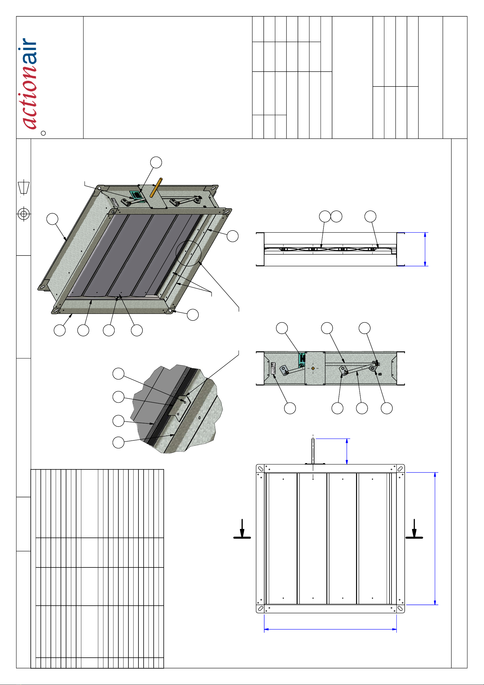
ITEM QTY DRAWINGNUMBER PARTNUMBER DESCRIPTION
1 2 ES35-001 SIDE FRAME
2 2 ES35-002 TOP & BOTTOMFRAME
3 SEE CHART ES50-003A CANN01835 TRIMBLADE
4 2 ES50-015 CNNN01833 ES50 BLADE STOP SEAL ASSEMBLY
5 2 ES36-005 CUNN01699 GASKET(SIDES)
6 SEE CHART ES50-006A CANN01817 STANDARD BLADE
7 8 ES35-007A/007C SEE DRAWING FLANGE CORNER BRACKET
8 1 (N>=3) ES35R-009 CSGN01802 LINKAGE TIEBAR
92N (WITHOUT TRIMBLADE)
2(N-1) (WITH TRIMBLADE) ES50-011A CNNN01836 ES50 BLADE SEAL
10 1 ES35-055 LNNN00010 DRIVING SHAFTLABEL
11 SEE DRAWING ES35R-016 CSGN01804 CROSSOVER LINKAGE "-"
12 SEE CHART ES50-050 SPACER
13 2N ES35-018 CPNN01690 BEARING
14 AS ITEM11 ES35-019 CSNN01691 "E" LINKAGE
15 N - ITEM14 ES35-020 CSNN01692 "F" LINKAGE
16 N USNN00073 E RING (E-25)
17 N ES35-027 CSZN01693 IDLER HEXAXLE
18 1 ES35-030 SEE DRAWING EXTENDED SHAFT KIT
19 1 ES50-054 LNNN00009 ES50 LABEL
20 2 (SEE NOTE 5) CNNN01933 FOAM
21 2 (SEE NOTE 5) ES50-056 CSGN01932 ES50 OVER TRAVEL STOP
22 4 (SEE NOTE 5) RSZN00054 FSD SELF PIERCE C'SK RIVET
N(NOB):THE NUMBER OF BLADES (SEE CHART)
PARTS LIST
DO NOT SCALE
ES50R−200
Draw No. 1
Rev. DIMENSIONS IN MILLIMETRES
C
RUSKIN AIR MANAGEMENT LIMITED
South Street, Whitstable
Kent CT5 3DU
Telephone: 01227 276100
Facsimile: 01227 264262
www.actionair.co.uk
ECN1031
16/05/2005
H Tang
Initials Dates
1
ES50R−200
Drawing No. Revision
Product
Part Number
Material
1
Rev Ecn
Ecn
Approved by
SEE PARTS LIST
N/A
Checked by
Drawn by
Finish
ES50R ASSEMBLY
Description
ES DAMPER
This drawing is confidential communication and is the property of Ruskin Air Management Limited and is returnable on request. It is not to be copied, loaned or communicated without the consent of Ruskin Air Management Limited.
This drawing should be considered uncontrolled if it is a printed copy, or has been transmitted outside of Ruskin Air Management Limited, electronically. The live version is the electronic copy held at Ruskin Air Management Ltd.
Please confirm the drawing issue before placing any orders which refer to this drawing.
A
A
NBDW
NBDH
D
NOTES:
1/ CLINCH THE BLADE STOPS ON THE TOP &
BOTTOM FRAMES (MAY ON THE SPACERS),
MAKE SURE THE BLADE STOPS PARALLEL TO
THE FRAME.
2/ AFTER ASSEMBLY, SEAL BLADE STOPS AND
SPACERS (IF PRESENT).
3/ STICK DRIVE SHAFT LABEL ON THE DRIVE
SIDE TO SHOW THE RECOMMENDED DRIVE
SHAFT LOCATION (SEE DRAWING ES35−021 ~
024).
4/ TAPE THE EXTENDED SHAFT KIT ON THE
TOP OF THE DAMPER.
5/ WHEN NBDW IS GREATER THAN 1000MM
AND WITH TRIM BLADES, STICK FOAMS (ITEM
20) ON THE TRIM BLADES, AND FIX ES50 OVER
TRAVEL STOP (ITEM 21) ON THE CENTRE OF
THE BLADE STOPS WITH RIVETS(ITEM 22).
6/ NBDW: NOMINAL BASE DAMPER WIDTH.
7/ NBDH: NOMINAL BASE DAMPER HEIGHT.
8/ D: FRAME DEPTH.
SEE NOTE 1 & 2
5
13
17
1
7
19
14
11
15
18
8
16
6
9
3
12
2
SEE NOTE 5
B
20 21 224
10
SEE NOTE 3
126
1221 HT 15/06/07
HT 18/06/07
MB 27/06/07


This manual suits for next models
3
Table of contents
Other Ruskin Fire And Smoke Damper manuals