OSBWT225-EN
10/13
INSTALLATION, OPERATION & MAINTENANCE INSTRUCTIONS
HANDLING & STORAGE
HANDLING
Do not drop or throw the product as it may break.
STORAGE
Store away from dust, moisture and direct sunlight.
If possible, store in the original package.
CHECKING
• Check the product code, power supply, and voltage
before installation.
• Make sure that the bolts are not loose.
INSTALLATION
PRECAUTIONS
• Flush the pipeline carefully before installing the
damper. Foreign particles, such as sand or pieces of
welding electrode, will damage the disk and seats.
• For dampers with specified flow direction (WT),
check the arrows on the product before piping.
• Damper is shipped closed. (allows quick piping.)
• Disc interference may also occur when damper is
installed in pipeline with smaller than normal inside
diameter such as thick wall pipe, or lining pipe.
Suitable corrective measurement must be taken
(taper boring the pipe or pipe liner, etc.)
PIPING FLANGES
• Gasket should be selected appropriately to suit the
fluid, pressure and temperature.
Use spring washer to prevent from decreasing
surface pressure gasket when the temperature
change happens frequently.
• Wafer type butterfly damper is put between two
seats of flanged-end and tightened with long bolts.
• Before bolts are tightened, damper should be
centered within the bolts to prevent possible disc
interference or damage by contact with the pipe or
flange.
• Tighten all bolts using crossover method to load the
joint evenly.
ENVIRONMENT
• Do not install in place where corrosive gas is present
or where vibration is heavy (0.5 G or more).
• When radiant heat causes the surface temperature
of the control unit to exceed 50°C, provide an
appropriate shielding plate.
• If there is a possibility that the fluid and drive part
freeze, please take measures to prevent freezing.
POSITIONING
Should be positioned through 90° upward from
horizontal. Provide space around the product to
allow manual operation, inspection and replacement
work.
Maintenance space for upper part of actuator.
AE (120 / 300 / 600) More than 105 mm
AE (02K / 06K) AD HD More than 120 mm
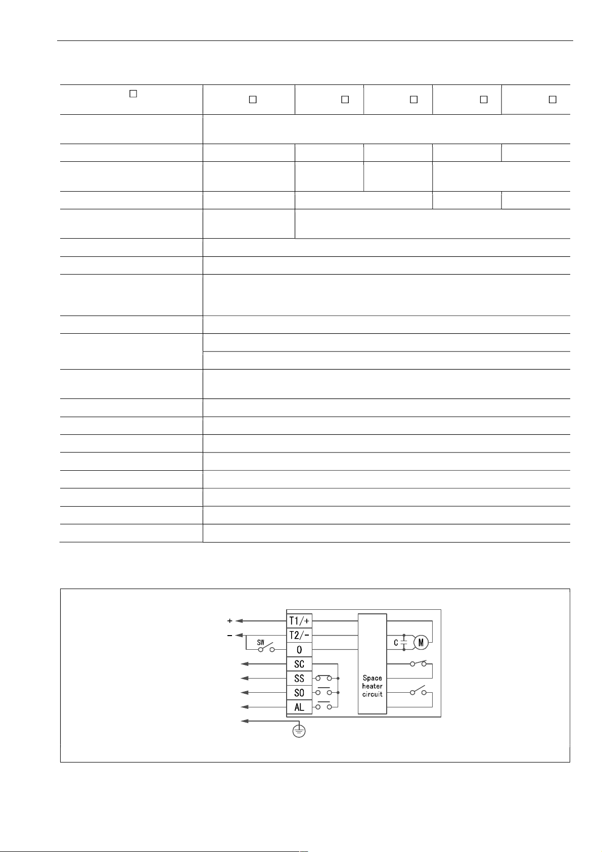
OTHER NOTES
Until the wiring is completed there must be no
condensation or flooding in the interior of the
actuator, after piping. Protective caps on the cable
gland are not waterproof.
INSULATION WORK
• For maintenance of gland packing, insulation should
be below the ground part.
• The upper part of the ground plate part is a heat
dissipation part, do not insulate it.