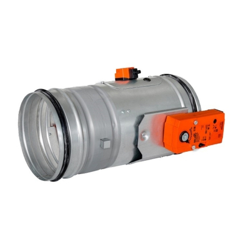
Komfovent LMV-D3-MF-F User manual

VARIABLE AIR VOLUME
DAMPERS
Installation instructions
EN

2SIA KOMFOVENT reserves the right to make changes without prior notice.
CONTENT
1. WHAT KOMFOVENT VARIABLE AIR FLOW DAMPER IS ........................................................................................................................3
2. GENERAL REQUIREMENTS FOR SAFETY...................................................................................................................................................5
3. EQUIPMENT FOR PERSONAL PROTECTION.............................................................................................................................................6
4. INSTALLATION INFORMATION......................................................................................................................................................................7
4.1. Analogue connection..............................................................................................................................................................................9
4.2. MP-bus connection............................................................................................................................................................................... 10
4.3. Modbus connection.............................................................................................................................................................................. 11
4.4. KNX connection...................................................................................................................................................................................... 12
5. STORAGE AND TRANSPORTATION........................................................................................................................................................... 13
6. PRODUCT LIFE CYCLE ................................................................................................................................................................................... 14
7. HYGIENE ASPECTS.......................................................................................................................................................................................... 15
8. ORDERING SAMPLE........................................................................................................................................................................................ 15
PLEASE READ THE INSTRUCTIONS CAREFULLY PRIOR TO ANY INSTALLATION WORKS!

3
SIA KOMFOVENT reserves the right to make changes without prior notice.
Fig. 1: VAV damper composition
1 – damper casing, 2 – damper blade, 3 – VAV control unit, 4, 7 – measuring hoses, 5, 6 – control unit measuring tubes,
8 – green push button and LED display, 9 – yellow push button and LED display, 10 – gear disengagement button,
11 – service plug
1.
WHAT KOMFOVENT VARIABLE AIR FLOW DAMPER IS
Variable air volume (VAV) damper is a part of heating, ventilating, and/or air-conditioning (HVAC) system. VAV damper
consists of damper casing, measuring unit and controller. Damper is fitted with a differential pressure sensor for measuring
the volume flow rate.
8
O: No power supply or fault
Illuminated: In operation
Flashing: Address mode: pulses according to set address (1 ... 16) when starting: reset to
factory setting (communication)
Press button: In standard mode: switches on angle of rotation adaptation
In address mode: confirmation of set address (1 ... 16)
9
O: The actuator is ready
Illuminated: Adaption or synchronizing process active or actuator in address mode (green LED
indicator flashing)
Flickering: Modbus communication active
Press button:
In operation (>3 s): switch address mode on and off
In address mode: address setting by pressing several times
When starting (>5 s): reset to factory setting (communication)
10
Press button: Gear disengaged, motor stops, manual override possible
Release button: Gear engaged, synchronization starts, followed by standard operation
11 Service plug For connecting parameterizing and service tools
Operating controls and indicators:
3
4
2
1
7
5
6
8
11
9
10

4SIA KOMFOVENT reserves the right to make changes without prior notice.
Standard delivery contains:
1 fully assembled VAV damper 1 installation instructions
1 label for setting Vmin and Vmax parameters 2 protective transportation caps (optional)
EN
VARIABLE AIR VOLUME DAMPERS
Installation manual
Variable Air Flow Damper
AIR FLOW DIRECTION
d160
VAV 160 + MHK12
Control mode
0-10V
Vmax
0000 m3/h
Vmin
0000 m3/h
Client:
SN 00000-00001
00.00.0000
00000-00001

5
SIA KOMFOVENT reserves the right to make changes without prior notice.
2.
GENERAL REQUIREMENTS FOR SAFETY
It is forbidden to modify the VAV damper or replace any unit part unless otherwise provided by KOMFOVENT. Only ori-
ginal replacement parts submitted by KOMFOVENT are allowed to be used. Qualied sta only are allowed to replace
parts or service the VAV damper.
WARNING! Danger of serious damage to health and risk of damage to property due to incorrect use!
Incorrect use of the electrical component could result in the creation of a dangerous situations.
Never use the VAV device:
• in explosion protected junctions;
• in any aircrafts;
• unless efficient protection against weather conditions not assured;
• in wet conditions (swimming pools, bathrooms, boats).
1. The actuator must not be used outside the specified field of application, especially in aircraft or in any
other airborne means of transport.
2. It may only be installed by suitably trained personnel. Any legal regulations or regulations issued by
authorities must be observed during installation.
3. The device may only be opened at the manufacturer‘s site. It does not contain any parts that can be
replaced or repaired by the user.
4. The cable must not be removed from the device.
5. When calculating the required torque, the specifications supplied by the damper manufacturers (cross-
section, design, installation site), and the air flow conditions must be observed.
6. The device contains electrical and electronic components and is not permitted to be disposed of as
household refuse. All locally valid regulations and requirements must be observed.

6SIA KOMFOVENT reserves the right to make changes without prior notice.
3.
EQUIPMENT FOR PERSONAL PROTECTION
Personal protective equipment must be worn for such types of work: VAV damper electrical installation, VAV damper me-
chanical connection to the air duct system (ductwork) and any type of service or maintenance works.
Protective gloves must be worn
Protective gloves protect hands
against abrasion, oily environment,
sharp metal parts and contact with
hot surfaces.
Protective industrial helmet must be
worn
Industrial helmets protect the head
against impact from objects falling from
above, by resisting and deflecting blows
to the head.
Protective boots must be worn
Protective boots protect the foot from
falling objects or compression and
prevent slipping on a slippery floor.

7
SIA KOMFOVENT reserves the right to make changes without prior notice.
4.
INSTALLATION INFORMATION
To avoid flow measurement deviation and unnecessary errors, the minimum distance before the VAV damper must be ob-
served (see Fig. 2).
Straight section of duct equal to 2xD (for circular ducts) or 2xB (for rectangular ducts) from 90° bend or Tpiece is the min-
imum requirement when installing VAV dampers.
Using smaller straight section will lead to a bigger flow measurement error. A bigger straight distance is recommended after
silencers, fire dampers and other ventilation duct system components.
2 × B
D (Ø)
2 × D
2 × D
2 × B
B
Fig. 2: Minimum distance between VAV damper and duct system ttings

8SIA KOMFOVENT reserves the right to make changes without prior notice.
Mounting the VAV damper onto the air duct system it is important to take into account the airflow direction. Required air-
flow direction is shown on the damper label and indicated with blue arrow (see Fig.3).
Fig. 3: VAV damper label
D-125
Variable Air Flow Damper
SN 00000-00001
00.00.0000
Control mode
0-10V
Vmax
114 m3/h
Vmin
67 m3/h
komfovent.com
Made in Latvia AIR FLOW DIRECTION
KOSC 125BMP 067114
VAV damper diameter
Vmin value
Vmax value
Unique serial No.
Control voltage
Arrow shows required air flow
direction
Each VAV damper is produced individually and configurated to fulfil the project requirements. Unique serial number shown
on the label should be used to identify damper designed location onto the mounting scheme.
VAV damper controllers are provisionally programmed to required Vmin and Vmax values at the factory.
For VAV damper connection, the matching supply voltage should be energized to the electrical components.
The connection should be must be carried out in such a way as specified in connection schemes.
The matching voltage values and the connection conditions should be respected!
Only qualied electricians are allowed to carry out work!
There are four possible main VAV damper connection types:
Analogue connection MP-Bus connection Modbus / BACnet connection KNX connection
LMV-D3-MF-F controller LMV-D3-MP controller LMV-D3-MOD controller LMV-D3-KNX controller

9
SIA KOMFOVENT reserves the right to make changes without prior notice.
4.1. Analogue connection
For analogue connection it is possible to connect controller 0...10 V or 2...10 V to the VAV damper and control the air volume,
depending on the given signal and set up.
Type Torque Power consumption Rating Weight
LMV-D3-MF-F 5 Nm 2 W 3.5 VA (max. 8 A @ 5 ms) Approx. 500 g
Damper is CLOSED via 0 ... 10 V reference signal (Mode 2 ... 10 V).
Setting parameters: Mode 2 … 10 V, Shut off level 0.1 V or 0.5 V.
If the required switching threshold of 0.1 V cannot be attained, the value can be switched to 0.5 V with PCTool.
Function Standard 0.1 V Shut-o level 0.5 V
Damper CLOSED <0.1 V <0.5 V
Vmin >0.1 ... 2 V >0.5 V ... 2 V
Vmin ... Vmax 2 ... 10 V 2 ... 10 V
In CAV applications shut-off level must not be set to 0.5 V, otherwise the open connection 3 is interpreted as damper CLOSED.
Wiring diagram 1: VAV, analogue reference signal Wiring diagram 2: VAV with shut-o (CLOSED), 2 ... 10 V mode
+
~
–
T
U
Y
ZUL
U
Y
ABL
T
T
1 2 3 5
1 2 3 5
+
~
–
T
U
Y
ZUL
U
Y
ABL
T
1 2 3 5
1 2 3 5
a b
Reference signal Vmin ... Vmax
0 ... 10V / 2 ... 10V
Tool / Actual value signal
Option Master / Slave Circuit
Reference signal Slave
Tool / Actual value signal
Reference signal Vmin ... Vmax
2 ... 10V
aDamper CLOSED / bVAV mode
Tool / Actual value signal
Option Master / Slave Circuit
Reference signal Slave
Tool / Actual value signal

10 SIA KOMFOVENT reserves the right to make changes without prior notice.
4.2. MP-bus connection
For MP-bus connection master/slave bus technology a defined number of slaves can be connected to a MP-Master unit.
Type Torque Power consumption Rating Weight
LMV-D3-MP 5 Nm 2 W 3.5 VA (max. 8 A @ 5 ms) Approx. 500 g
Damper is CLOSED via 0 ... 10 V reference signal (Mode 2 ... 10 V).
Setting parameters: Mode 2 … 10 V, Shut off level 0.1 V or 0.5 V.
If the required switching threshold of 0.1 V cannot be attained, the value can be switched to 0.5 V with PCTool.
Function Standard 0.1 V Shut-o level 0.5 V
Damper CLOSED <0.1 V <0.5 V
Vmin >0.1 ... 2 V >0.5 V ... 2 V
Vmin ... Vmax 2 ... 10 V 2 ... 10 V
In CAV applications shut-off level must not be set to 0.5 V, otherwise the open connection 3 is interpreted as damper CLOSED.
Wiring diagram 1: VAV, analogue reference signal Wiring diagram 2: VAV with shut-o (CLOSED), 2 ... 10 V mode
+
~
–
T
U
Y
ZUL
U
Y
ABL
T
T
1 2 3 5
1 2 3 5
+
~
–
T
U
Y
ZUL
U
Y
ABL
T
1 2 3 5
1 2 3 5
a b
Reference signal Vmin ... Vmax
0 ... 10V / 2 ... 10V
Tool / Actual value signal
Option Master / Slave Circuit
Reference signal Slave
Tool / Actual value signal
Reference signal Vmin ... Vmax
2 ... 10V
aDamper CLOSED / bVAV mode
Tool / Actual value signal
Option Master / Slave Circuit
Reference signal Slave
Tool / Actual value signal

11
SIA KOMFOVENT reserves the right to make changes without prior notice.
4.3. Modbus connection
For Modbus connection the Modbus protocol is used to establish master-slave / client-server communication between intel-
ligent devices. Using Modbus, a master (e.g. automation station) and several slaves can be interconnected.
Type Torque Power consumption Rating Weight
LMV-D3-MOD 5 Nm 2 W 3.5 VA (max. 8 A @ 5 ms) Approx. 500 g
BACnet MS/TP / Modbus RTU
+
~
–
T
+
~
–
T
1 2 3 5 6 7 1 2 3 5 6 7
GND
D–
D+
AC/DC 24 V AC/DC 24 V
D– D+ D– D+
Cable colours:
1 = black
2 = red
3 = white
5 = orange
6 = pink
7 = gray
Signal assignement
Modbus:
C1 = D–
= A
C2 = D+ = A
+
~
–
T
1 2 3 5 6 7
MFT D– D+
D–
D+
Switching contact
requirements:
The switching
contact must be
able to switch a
current of 16 mA at
24 V accurately
Connection with switching contact, e.g. Δp-monitor Connection of active sensors, e.g. 0...10 V @ 0...50 °C
Possible voltage range:
0 ... 32 V (resolution 30 mV)
+
~
–
T
1 2 3 5 6 7
MFT D– D+
D–
D+
+
~
–
T
GND
D–
D+
AC/DC 24 V
Y
U
1 2 3 5 6 7
D– D+
DC (0)2 ... 10 V
DC 2 ... 10 V
BACnet MS/TP / Modbus RTU with analog setpoint (hybrid mode) Operating on the MP-Bus
+
~
–
T
D– D+
1 2 3 5 6 7
Y
U
Sensor
MP

12 SIA KOMFOVENT reserves the right to make changes without prior notice.
4.4. KNX connection
For KNX connection KNX devices are generally connected by a twisted pair bus and can be modified from a controller. Below
is a connection scheme for KNX type actuators.
Type Torque Power consumption Rating Weight
LMV-D3-KNX 5 Nm 2 W 4 VA (max. 8 A @ 5 ms) Approx. 500 g
+
~
–
T
MFT D+ D–
1 2 3 5 6 7
KNX
KNX signal assignment:
D+ = KNX+ (pink > red)
D – = KNX – (grey > black)
The connection to the KNX line should
take place via WAGO connection
terminals 222/221
Connection without sensor
+
~
–
T
KNX
1 2 3 5 6 7
MFT D+ D–
Switching contact
requirements:
The switching contact
must be able to switch a
current of 16 mA at 24 V
accurately
Connection with switching contact, e.g. Δp-monitor Connection of active sensors, e.g. 0...10 V @ 0...50 °C
Possible voltage range:
0 ... 32 V (resolution 30 mV)
+
~
–
T
MFT D+ D–
1 2 3 5 6 7
KNX
~T
Y
MFT
D+ D–
1 2 3 5 6 7
KNX
a b c d
Local override control
If no sensor is integrated, then connection 3 (Y)
is available for the protective circuit of a local
override control.
Options: CLOSED – Vmax – OPEN
Note: Functions only with AC 24 V supply!
aDamper CLOSED
bVmax
cDamper OPEN
dBus mode

13
SIA KOMFOVENT reserves the right to make changes without prior notice.
5.
STORAGE AND TRANSPORTATION
Please check received VAV dampers directly after delivery for transportation spoilage and other nonconformities.
VAV damper cannot be installed if there are visible signs of electrical parts damage!
VAV dampers can be transported by any means of transport. During transportation, the dampers must be fixed in such a way
as to prevent their movement and deformation. VAV dampers should be stored indoors in a ventilated area under normal
conditions. Recommended storage temperature range is 5 - 35 °C. Dampers must be protected from direct atmospheric
exposure, direct sunlight, rainfall or wind.
During storage and transportation, the VAV controller must be protected from loading.
It is recommended to keep the original boxes and / or protective caps or lids to avoid damper measuring tubes contamina-
tion with dust and sweepings. Please do not remove the protective caps until just before installation.

14 SIA KOMFOVENT reserves the right to make changes without prior notice.
6.
PRODUCT LIFE CYCLE
VAV damper is designed in nature-way to have minimum impact on environment.
RAW MATERIALS
Casing Blade
Galvanized sheet metal as per EN 10346-15 Continuously hot-dip coated steel flat
products for cold forming - Technical delivery conditions. DX51D: Bending and
profiling quality 0.7 mm chemically passivated sheet metal.
Zinc coating thickness per surface in the single spot test - 15 to 27 μm.
Axes Hot-rolled steel as per EN 10025-2:2004 European standard for hot-rolled structural
steel. Part 2 - Technical delivery conditions for nonalloy structural steels.
Sealing rings
EPDM rubber with self-lubricating properties.
Shore A hardness 64.
Elongation at break over 200% as per ISO 37-2017 Rubber, vulcanized or
thermoplastic — Determination of tensile stress-strain properties. Ozon resistance
with no cracks under the conditions 96h/20%/50pphm/30°C as per ISO 1431-1-2012
Rubber, vulcanized or thermoplastic - Resistance to ozone cracking -- Part 1: Static
and dynamic strain testing.
Aluminum tubes Aluminum tube 10x10x1 mm as per EN 755-1:2008 Aluminum and aluminum alloys.
Extruded rod/bar, tube and profiles. Technical conditions for inspection and delivery.
Digital VAV controller Control pollution degree categorized by Underwriters Laboratories (UL) and IEC: 3.
Protection class as per IEC/E III Safety: extra-low voltage.
Other materials
Plastic fittings, stainless steel connecting plate, bushings, galvanized fasteners,
polymer material stickers, vegetable grease, talc (in average less than 5% of the
product total weight).
ENERGY
CONSUMPTION
Space heating Heat-pumping technology is used to heat the manufacturing places. Additionally,
natural gas is in use.
Water heating Compressor’s heat exchanger additionally is used for supplied water heating.
EMISSIONS
Air emissions Automated casing production line is equipped with smoke receiver.
The new generation laser cutting machine CO2 emission amount is reduced by 25%.
Water emissions There are no any water emissions.
PACKAGING
Primary packaging Cardboard box producer has received Ecolabel, FSC® and PEFC Chain of custody
Certificates.
Secondary packaging EUR pallet producer has received PEFC Chain of custody Certificates and provides
pallets restoration to decrease environmental influence.
ENVIRONMENTAL
LOAD
Product life cycle Product life cycle normally is equal to air duct lifespan, i.e. 30 years.
Product utilization Product utilization has no environmental influence.
Up to 25% of the total steel content can be recovered for further use.
Packaging utilization All packaging materials are 100% recyclable.

15
SIA KOMFOVENT reserves the right to make changes without prior notice.
7.
HYGIENE ASPECTS
As VAV damper manufacturer Komfovent Ltd. developed a product composed only of materials and components with ap-
proved quality and safety properties.
The hygiene check was conducted for the following used materials:
• Stainless steel AISI 304;
• Galvanized steel DX51D+Z275;
• Mineral wool Isover KT-40;
• VAV-Compact MP, VAV-Compact MOD and VAV-Compact MF controllers;
• Insulating rubber CO5/HD0426.
Latvian Health Inspectorate under Ministry of Health of the republic of Latvia conducted a VAV damper hygiene assess-
ment and authorized the safe VAV dampers application in air distributing systems installed in public, residential and
industrial facilities.
8.
ORDERING SAMPLE
KOS - C - I - N - 160 - BMF - 0 - 100-300
Damper type: KOS
C – circular
R – rectangular
I – with insulation 50 mm
No entry – without insulation
N – stainless steel casing
No entry – galvanized steel casing
Diameter: 100/125/160/200/250/315/355/400/500/600
Acturator type: BMF – analogue connection
BMP – MP-bus connection
BMD – Modbus communication
BMDbn – BACnet communication
BKX – KNX communication
Control signal: 0– 0..10 V
2– 2..10 V
Vmin-Vmax – defined air flow, m3/h

SIA KOMFOVENT
1, Bukaisu street,
LV-1004, Riga, Latvia
info.lv@komfovent.com
www.komfovent.com
2023-02
Table of contents
Other Komfovent Fire And Smoke Damper manuals
Popular Fire And Smoke Damper manuals by other brands
Swegon
Swegon BLBd Installation, commissioning maintenance

klimaoprema
klimaoprema FD25 Technical manual

Lindab
Lindab RECTANGULAR Series Installation booklet

Madel
Madel FBK-EIS-120 Installation and use

Trox Technik
Trox Technik FKRS-EU Installation and operating manual

Mandik
Mandik FDMR installation instructions