manuals.online logo
Brands
  1. Home
  2. •
  3. Brands
  4. •
  5. Johnson Controls
  6. •
  7. Switch
  8. •
  9. Johnson Controls F59D Service manual

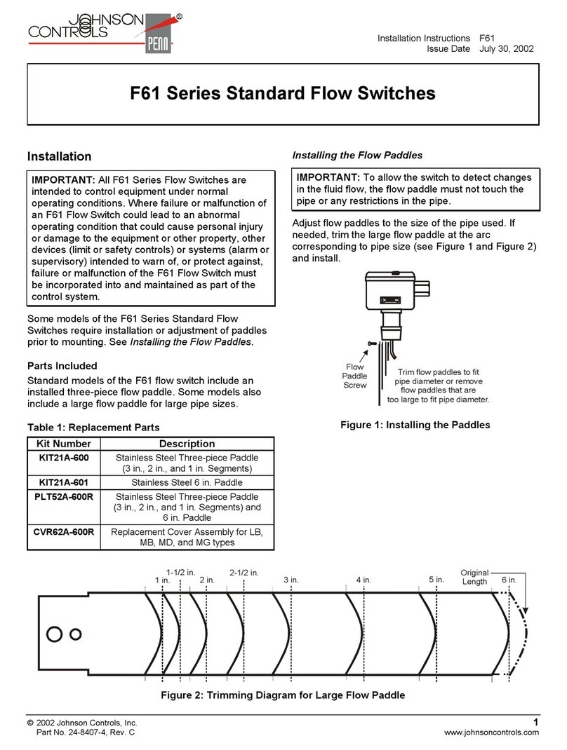
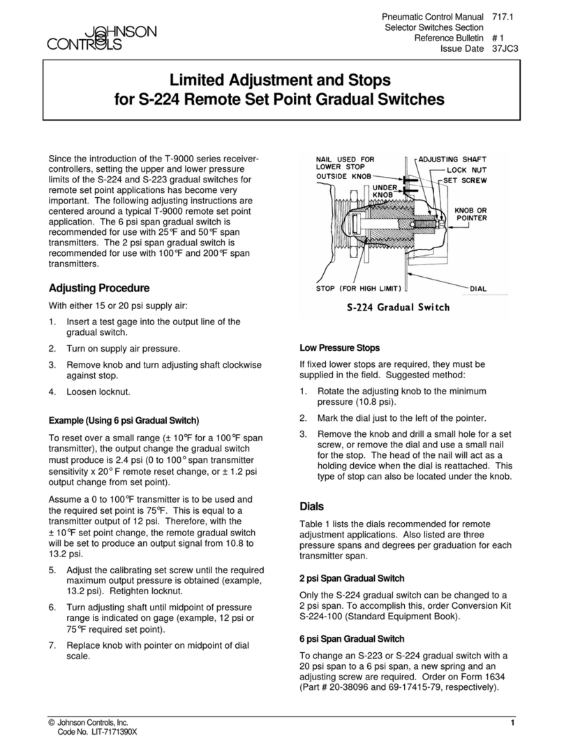
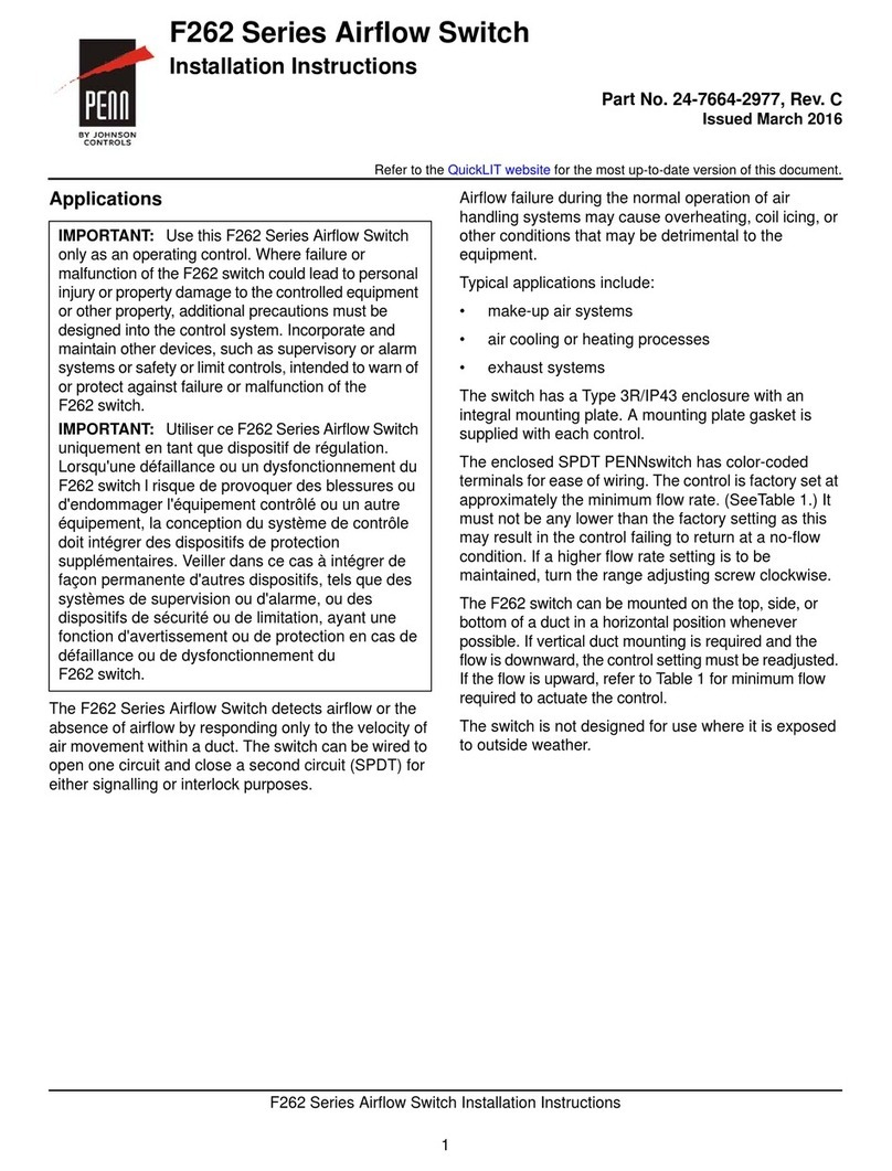
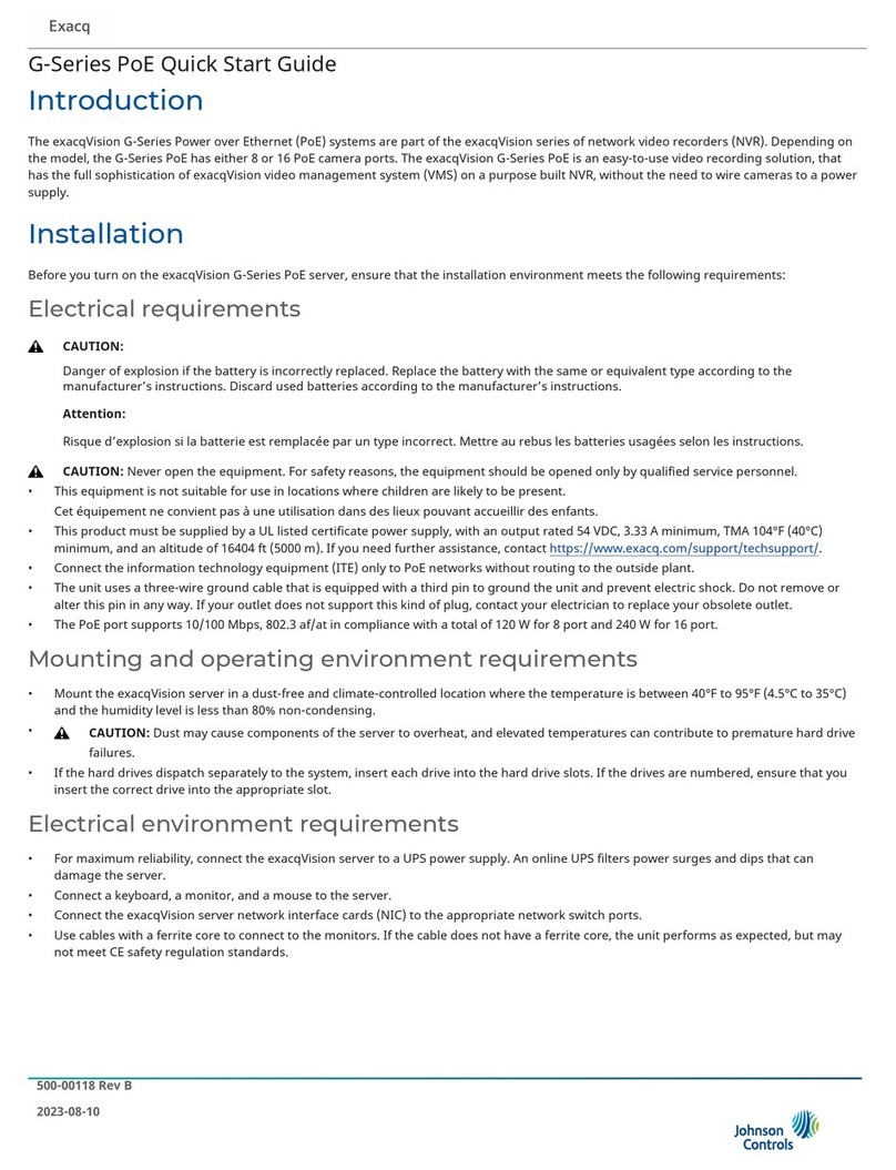
Johnson Controls F59D Service manual

Liquid Level and Flow Controls
Technical Bulletin F59D
Issue Date 0102
© 2002 Johnson Controls, Inc. 1
Part No. 24-7664-2357, Rev. — www.johnsoncontrols.com
Type F59D Liquid Level Switch - Float or Weight
Operated for Sumps and Open Tanks
Application
Type F59D single-pole switches
are designed to control the liquid
level in sumps or open tanks. It
is a suitable replacement switch
on submersible and pedestal
type sump pumps. The switches
are supplied with switched
power cord for sump operation
(close contacts on liquid rise)
and factory adjusted to operate
with weights supplied by
Johnson Controls. The F59D
can also be operated by a center
hole or spud-type float. (See
Adjustments instructions and
Fig. 6.) The switch can be
rotated 180 degrees and
adjusted to open contacts on
liquid rise for “Open Tank” (tank
filling) operation. (See “Tank
Filling Operations.”)
The switches should not be
installed where the temperature
at the weights exceeds 150°F
(66°C). The temperature at the
switch must not exceed 140°F
(60°C).
All F59 Series switches are
designed for use only as
operating controls. Where an
operating control failure
would result in personal injury
and/or loss of property, it is
the responsibility of the
installer to add devices
(safety, limit controls) or
systems (alarm, supervisory
systems) that protect against,
or warn of, control failure.
Installation
For sump operation, mount the
switch with the counterbalance
spring and adjusting screw
pointing down. A mounting
clamp is provided with each
switch for easy mounting to the
discharge pipe. It replaces any
type of float or weight operated
switch.
The adjusting screw and spring
located below the operating
lever are factory set for
operation with the two weights
and cable to close the switch
contacts when liquid level rises.
The switch should be mounted
so the weights and cable hang
freely without interference.
To install switch proceed as
follows:
1. Open the mounting clamp
supplied with the switch.
2. Place the clamp around
discharge pipe or pedestal.
3. Hook both sides of the
switch mounting bracket
over the clamp between the
clamp and the pipe.
4. Tighten clamp securely to
hold switch firmly in place. Fig. 1 -- Type F59D liquid level
switch with weight kit.
2 F59D Technical Bulletin
To install weights and cable
proceed as follows:
!
CAUTION: Do not drop
weights. The weights could
crack causing them to
waterlog. This would
prevent the switch from
operating automatically and
would require a new weight
kit.
For Plastic Cable
1. Place the cable eyelet over
the hook on the switch
lever. Do not crimp or bend
the switch lever hook.
2. Thread upper weight onto
plastic cable with large hole
down.
3. Determine upper liquid level
(pump turn-on level) and tie
a knot in the plastic cable to
support weight at the
selected liquid level. (See
Fig. 3.)
4. Slide the weight down over
the knot.
5. Thread lower weight onto
plastic cable.
6. Determine lower liquid level
(pump turnoff level) and tie
a knot in plastic cable to
support weight at the
selected liquid level.
7. Slid the weight down over
the knot.
8. Cut off excess cable below
lower weight after checking
to be sure weights are at
the correct level. (See
Fig. 2.)
For Wire Cable
1. Place the cable eyelet over
the hook on the switch
lever. Do not crimp or bend
the switch lever hook.
2. Thread upper weight onto
wire cable.
3. Thread upper weight holder
onto wire cable to support
weight at the selected liquid
level. (See Fig. 4.)
F59D Technical Bulletin 3
4. Thread lower weight on wire
cable.
5. Thread lower weight holder
onto wire cable to support
weight at the selected liquid
level.
6. Adjust the weight holders
and weights as shown in
Fig. 2.
The top weight should be set
about six inches below the top of
floor and the bottom weight set
even with the top of the drainer
discharge opening.
Always leave about three inches
of water at the bottom of the
sump. A lower water level may
result in the drainer running in a
dry sump.
Adjustments
The switch contacts should open
or cutout (sump operation) when
the liquid level drops to expose
about one half of the lower
weight. (See Fig. 5.) If the
switch operates before this level
is reached the counterbalance
spring is too tight and should be
loosened slightly. Turn adjusting
screw counterclockwise (out of
spring). (See Fig. 1.) Operation
should be rechecked for proper
operation.
The switch may also be used
with spud-type floats. Spud-type
floats are available at plumbing
supply or hardware stores.
However, they are not available
from the Systems Products
Division. If these accessories
are used, the following notes
should be helpful.
Center Hole Floats (Fig. 6)
When a center hole float is used
it is necessary to adjust the
counterbalance spring so
contacts will remain closed
(operating lever up) when the
weight of a float rod only hangs
from the operating lever. The
length of a 1/4 in. brass float rod
is limited to 3-1/2 feet. The float
rod should be inserted through
the 5/16 in. hole in the operating
lever. Stops should be about
3/8 in. apart to prevent binding
at the lever. IMPORTANT: Line
up float rod guide and hole in
operating lever of switch to be
sure there will be no
misalignment and binding.
To check out center hole float
operation proceed as follows:
With no liquid in the sump, slide
the float to upper stop and push
up the operating lever of the
switch. Lower the float slightly
so the weight of the rod is
hanging freely from the
operating lever. The switch
contacts should remain closed.
If contacts open, the
counterbalance spring is too
tight and should be loosened by
turning screw counterclockwise
(out of spring). (See Fig. 1.)
Spring should be just loose
enough to allow operating lever
to support weight of float rod
only. Recheck to insure proper
operation.
Spud-Type Float (Fig. 6)
To check out spud-type float
operation it is necessary to
adjust the counterbalance spring
so operating lever can be
pushed up or down and the lever
will remain in either position with
nothing connected to the
operating lever. Tighten
adjusting screw into spring until
this can be done. To check out
spud float operation, operate
sump pump with liquid to check
out levels of operation. If the
switch does not operate,
4 F59D Technical Bulletin
recheck above instructions. If
difficulty is not solved, the float
may not be of correct size. An
undersized float will not have
sufficient buoyancy to push the
rod up to close contacts while
and underweight float will not
weigh enough to pull the
contacts open.
Tank Filling Operation
Turn switch upside down so
adjusting screw is at the top and
adjust as follows:
1. Loosen spring.
2. Depress switch lever and
move spring from position
“A” to position “B.” (See
Fig. 7.)
3. Turn adjusting screw
clockwise until contacts
open on liquid rise.
4. Remove mounting bracket
and remount with arms
pointing down.
Wiring
!
WARNING: Disconnect
power supply before
making wiring connection
if new outlet must be
installed to avoid
possible electrical shock
or damage to equipment.
Connect the switch power cord
plug into electrical outlet. The
electrical outlet must be three-
prong type. If the outlet is of the
two-prong type, use an adapter
(purchase locally) to connect the
switch plug. (See Fig. 9.)
Insert the pump power cord plug
into the switch power cord plug.
The pump power cord will also
require a three-prong plug.
!
CAUTION: Do not use an
extension cord. The green
wire on the adapter must be
connected to a ground.
Connect the green ground
wire to the faceplate screw
of the electrical outlet box
or to a separate ground
wire clamped to a grounded
cold water pipe.
NEVER REMOVE THE
CENTER LUG OF THE
SWITCH PLUG.
Grounded cold water pipe must
have metal continuity to
electrical ground. If continuity is
interrupted by plastic, rubber, or
other electrical insulating
connectors such as hoses,
fittings, washers or gaskets
(including water meter or pump)
a metal bypass must be used.
Any electrically insulated
connector should be jumped
with a length of #4 AWG copper
wire securely clamped at both
ends. (See Fig. 10.)
Checkout Procedure
The operation should be
rechecked to be sure that the
switch contacts close when the
liquid level rises and covers
about one half of the upper
weight. After the switch is
installed it should be run through
a complete cycle to be sure all
components are functioning
correctly.
Repairs and Replacement
The weights and cable can be
replaced in the field. Other
repairs must not be made. The
weight kit includes two weights
and cable complete with eyelet.
Replacement kits are available
with the following cable lengths:
Replacement switches and weight
kits may be obtained from your
nearest Johnson Controls distributor.
When ordering a replacement switch
or kit, give complete Product Number
found on the switch or weight Kit
Number from the table.
Controls Group www.johnsoncontrols.com
507 E. Michigan Street
P.O. Box 423 Printed in U.S.A.
Milwaukee, WI 53202

Other Johnson Controls Switch manuals

Johnson Controls G Series User manual

Johnson Controls

Johnson Controls G Series User manual

Johnson Controls exacqVision G Series User manual

Johnson Controls

Johnson Controls exacqVision G Series User manual

Johnson Controls OLS-2000 Manual

Johnson Controls

Johnson Controls OLS-2000 Manual

Johnson Controls F61 series User manual

Johnson Controls

Johnson Controls F61 series User manual

Johnson Controls CSDECM-ADJ Series User manual

Johnson Controls

Johnson Controls CSDECM-ADJ Series User manual

Johnson Controls F61 Series User manual

Johnson Controls

Johnson Controls F61 Series User manual

Johnson Controls Penn F262 Series User manual

Johnson Controls

Johnson Controls Penn F262 Series User manual

Johnson Controls FS80-C User manual

Johnson Controls

Johnson Controls FS80-C User manual

Johnson Controls IQ Outlet User manual

Johnson Controls

Johnson Controls IQ Outlet User manual

Johnson Controls SBH300 User manual

Johnson Controls

Johnson Controls SBH300 User manual

Johnson Controls S-224 User manual

Johnson Controls

Johnson Controls S-224 User manual

Johnson Controls IQ4 User manual

Johnson Controls

Johnson Controls IQ4 User manual

Johnson Controls M9300 Series User manual

Johnson Controls

Johnson Controls M9300 Series User manual

Popular Switch manuals by other brands

Dell 8 Getting started guide

Dell

Dell 8 Getting started guide

Unitek D1078A user manual

Unitek

Unitek D1078A user manual

IDK FDX-16 Command reference guide

IDK

IDK FDX-16 Command reference guide

DirectConnect DCFG51000 user manual

DirectConnect

DirectConnect DCFG51000 user manual

EverFocus ES0812-31 user manual

EverFocus

EverFocus ES0812-31 user manual

Edimax ES-5800D+ user manual

Edimax

Edimax ES-5800D+ user manual

Niles IPC-6 install guide

Niles

Niles IPC-6 install guide

Canyon DS-3 quick guide

Canyon

Canyon DS-3 quick guide

GE 15132 manual

GE

GE 15132 manual

H3C S9500 Series Operation manual

H3C

H3C S9500 Series Operation manual

Venus KVM 8 user manual

Venus

Venus KVM 8 user manual

Balluff BES M30MF2-PSC15F-BV02-EXD user guide

Balluff

Balluff BES M30MF2-PSC15F-BV02-EXD user guide

DCB PAS v2 user guide

DCB

DCB PAS v2 user guide

Altusen KH-88 Quick start quide

Altusen

Altusen KH-88 Quick start quide

Lantech IES-2008B-DNV user manual

Lantech

Lantech IES-2008B-DNV user manual

Altimium SCA42T-CODEC user manual

Altimium

Altimium SCA42T-CODEC user manual

Marshall Amplification VMV-402-SH user manual

Marshall Amplification

Marshall Amplification VMV-402-SH user manual

iNels RFSTI-11 installation manual

iNels

iNels RFSTI-11 installation manual

manuals.online logo
manuals.online logoBrands
  • About & Mission
  • Contact us
  • Privacy Policy
  • Terms and Conditions

Copyright 2025 Manuals.Online. All Rights Reserved.