Mounting
The transmitter installs directly into any air duct with a
minimum width or diameter of 10 in. (25.5 cm).
- Select a suitable installation area in the middle of
the duct wall.
- To achieve the best reading, do not place in an area
where air stratification may be present.
- Mount the sensor at least 5 ft. (1.5 m) in either
direction from elbows, dampers, filters, or other
duct restrictions.
- Avoid areas that expose the transmitter to
vibrations or rapid temperature changes.
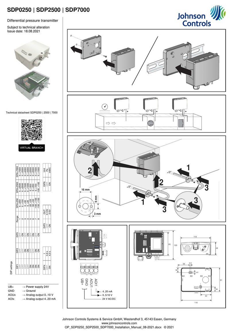
To install the transmitter, complete the following steps:
1. When you select a suitable spot, drill a 0.6 in. (15
mm) to 0.75 in. (20 mm) hole for the probe.
2. Slide the probe into the drilled hole until the
enclosure is flush against the duct. The airflow
direction is not important.
3. Secure the enclosure to the duct with two No. 10 x
1 in. (25 mm) self-tapping screws (not provided).
4. Tighten the screws until the enclosure is tight
against the duct so that there is no movement
of the enclosure. A foam gasket on the back of
the enclosure provides a tight seal against any air
leaks. See Step 1 in Figure 3.
5. The enclosure includes a hinged cover with a latch.
To open the cover, pull slightly on the latch on the
right side of the enclosure. At the same time, pull
on the cover as shown in Step 2 of Figure 3.
6. A 0.5 in. NPT threaded connection hole is in the
bottom of the enclosure. Screw the EMT or cable
gland connector into the threaded connection hole
until tight. See Step 3 in Figure 3.
Note: Preferably use weatherproof EMT or
cable gland fittings. The E-style enclosure
includes 0.5 in. NPT to M16 thread adaptor
and cable gland fitting.
7. Make wire connections as shown in the wire
diagram in Wiring.
8. Swing the door closed until it securely latches. For
added security, install the two provided screws in
the integrated screw tabs. See Step 4 of Figure 3.
Wiring
• Deactivate the 24 VAC/DC power supply before you
make all connections to the device to prevent electrical
shock or equipment damage.
• Use 14 AWG to 22 AWG shielded wiring for all
connections and do not locate the device wires in the
same conduit with wiring that supplies inductive loads
such as motors. Make all connections in accordance
with national and local codes.
• Pull at least 6 in. (15 cm) of wire into the enclosure,
then complete the wiring connection according to
the wire diagram for the applicable power supply and
output signal type. See Figure 4.
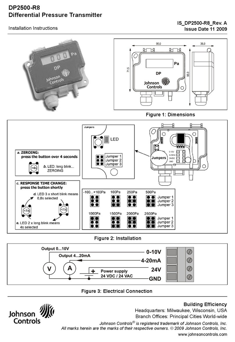
• Place the output switch in the required position to
select the required signal output type (mA or VDC), as
shown in Step 2 of Figure 4. The factory default setting
is 4 mA to 20 mA.
• If you select mA, no further output set up is required.
If you select VOLT output as shown in Figure 5, place
the voltage output switch to the required span position,
that is 10 VDC = 0 VDC to 10 VDC. The factory default
setting is 0 VDC to 10 VDC. See Step 1 of Figure 4.
• Connect the DC positive or the AC voltage hot side to
the PWR terminal. For voltage output or AC power,
connect the supply common to the COM terminal.
The device is reverse voltage-protected and does
not operate if you connect it backwards. The device
contains a half-wave power supply so the supply
common is the same as the signal common. See Step 3
of Figure 4.
• The analog output is available on the OUT terminal.
Check the controller Analog Input to determine the
correct connection before you apply power as shown in
Step 3 of Figure 4.
HT-69020NP-0, HT-69030NP-0 Duct Probe RH Transmitter Installation Guide2
