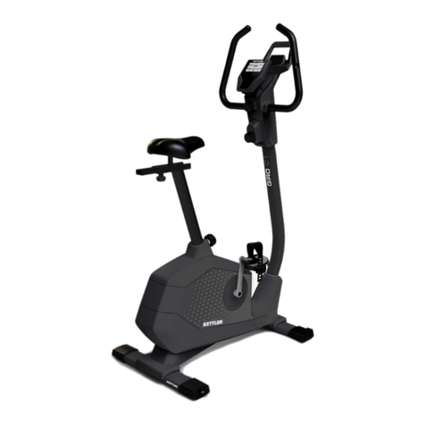
Johnson JPC-5100 User manual

o
JPB-5100
o
JPS-5100
o
JAR-6000
o
JPC-5100
o
JPE-5100
o
JAR-5100

TABLE OF CONTENTS
nSECTION 1: WIRING DIAGRAM
oCONTROL BOARD WIRING DIAGRAM (JPC/B-5100).............................1-1
oCONTROL BOARD WIRING DIAGRAM (JPS-5100)................................1-2
oCONTROL BOARD WIRING DIAGRAM (JPE-5100)................................1-3
oCONSOLE BACKSIDE (EAR CLIP SENSOR)...........................................1-4
oCONSOLE BACKSIDE (HAND PULSE)...................................................1-5
oWIRING DIAGRAM (JPC/B-5100).............................................................1-6
oWIRING DIAGRAM (JPS-5100)................................................................1-7
oWIRING DIAGRAM (JAR-5100)................................................................1-8
oWIRING DIAGRAM (JAE-5100)................................................................1-9
nSECTION 2: TROUBLESHLOOTINGS
JPC/B/S/E-5100
oNo display on the console or the display is dim..........................................2-1
oNo RPM is displayed during the exercise (JPC/B/S).................................2-2
oAll or some of the keys have no function......................................................2-3
oFeel the resistance increase/decrease or fell no resistance(JPC/B/S)........2-4
oFeel the resistance increase/decrease or feel no resistance (JPE)..............2-5
oFeel slipping while pedaling.......................................................................2-6
oKnocking or creaking noise..........................................................................2-7
oNo pulse is displayed on the console (Ear clip sensor)...............................2-8
oNo pulse is displayed on the console (Chest belt type)...............................2-9
oNo pulse is displayed on the console (Hand pulse type)..............................2-10
oConsole diagnostics mode...........................................................................2-11
JAR-5100
oNo display is on the console while any function key is pressed...................2-12
oNo display is on the console while adjusting the seat but there is display while
any key is pressed............................................................................................2-13
oConsole will not function properly...............................................................2-14
o“Count”value will not increase while adjusting the seat..........................2-15
JAR-6000
oNo display on the console..............................................................................2-16
o“SPM”value won’t increase while running the rower................................2-17
oNo pulse display on the console....................................................................2-18

TABLE OF CONTENTS
nSECTION 3: PARTS REPLACEMENT
nGENERAL (JPC/B/S/E)
oCONSOLE.......................................................................................3-1
oCONSOLE CABLE......................................................................3-2
oCONTROL BOARD.....................................................................3-3
oGENERATOR OR ELECTROMAGNET BRAKE SET..................3-4
nJPC/B-5100
oCRANK............................................................................................3-5
oPEDAL............................................................................................3-6
oPOLY-VBELT 400/380J6................................................................3-7
oPOLY-VBELT 500/440J8................................................................3-8
oAXLE.......................................................................................3-9
oFRONT PULLEY.......................................................................3-10
oBALL BEARINGS...........................................................................3-11
nJPS-5100
oPOLY-VBELT 430J6.......................................................................3-12
oPOLY-VBELT 430J8.......................................................................3-13
oCHAIN OR SPRING.....................................................................3-14
oSENSOR............................................................................................3-15
oFOOT PAD....................................................................................................3-16
oBALL BEARINGS.............................................................................3-17
nJPE-5100
oCRANK.............................................................................................3-18
oPEDAL.............................................................................................3-19
oPOLY-VBELT 430J12......................................................................3-20
oPOLY-VBELT 430J6........................................................................3-21
oPULLEY AXLE..............................................................................3-22
oAXLE.........................................................................................3-23
oROLLER............................................................................................3-24
oSENSOR............................................................................................3-25
nJAR-5100
oCONSOLE.......................................................................................3-26
oCONSOLE CABLE.......................................................................3-27
oSENSOR............................................................................................3-28
oSEAT.........................................................................................................3-29
oDRIVE BELT 3V-530......................................................................3-30
oNYLON ROPE.............................................................................3-31
oTENSION SPRING SET.................................................................3-32

TABLE OF CONTENTS
nSECTION 4: PREVENTIVE MAINTENANCE
¨CLEANING THE GROOVES.......................................................4-1
¨RE-LUBRICATING THE CHAIN & GEAR (for JPS)................4-2
¨CLEANING THE RAIL AND ROOLER(JPE5100)......................4-3
nSECTION 5: SERVICE FORM
oFIELD FAILURE REPORT.........................................................5-1
oPARTS ORDER FORM................................................................5-2
oWARRANTY CLAIM FORM........................................................5-3
Revision: 1.0 Date: 2001/06/01

SECTION 1
WIRING DIAGRAM
Revision: 1.0 Date: 2001/06/01

JPC/B-5100 CONTROL BOARD WIRING DIAGRAM
ØA1 : 3-pin terminal to the generator
ØA2 : 2-pin terminal to the electromagnet
ØA3 : 4-pin terminal to the console
1-1 Revision: 1.0 Date: 2001/06/01

JPS-5100 CONTROL BOARD WIRING DIAGRAM
ØA1 : 3-pin terminal to the generator
ØA2 : 2-pin terminal to the electromagnet
ØA3 : 2-pin terminal to the output of the adapter
ØA4 : 4-pin terminal to the console
1-2 Revision: 1.0 Date: 2001/06/01

JPE-5100 CONTROL BOARD WIRING DIAGRAM
ØA1 : 3-pin terminal to the electromagnet brake set
ØA2 : 2-pin terminal to the adapter
ØA3 : 3-pin terminal to the console
ØA4: grounding wire to frame
A4 A1
A2
A3
1-3Revision: 1.0 Date: 2001/06/01

CONSOLE BACKSIDE (EAR CLIP SENSOR)
ØA : console cable -> MCB A4
ØB : ear clip cable
ØC : console power switch
1-4Revision: 1.0 Date: 2001/06/01

CONSOLE BACKSIDE (HAND PULSE)
ØA : console cable -> MCB A4
ØB : hand pulse cable (right)
ØC : hand pulse cable (left)
ØD : console power switch
1-5Revision: 1.0 Date: 2001/06/01

JPC/B-5100 WIRING DIAGRAM
1-6Revision: 1.0 Date: 2001/06/01

JPS-5100 WIRING DIAGRAM
1-7Revision: 1.0 Date: 2001/06/01

JAR-5100 WIRING DIAGRAM
1-8Revision: 1.0 Date: 2001/06/01

JPE-5100 WIRING DIAGRAM
1-9Revision: 1.0 Date: 2001/06/01

SECTION 2
TROUBLESHOOTINGS
Pedal speed has to be over 30 rpm for
troubleshooting at anytime for
JPC/B-5100.
Revision: 1.0 Date: 2001/06/01

No display on the console or the display is dim(JPC/B/S/E)
Possible causes:
1. Console is damaged or
the console cable is not
connected properly.
2. Poor connection to all
the terminals on the
control board.
3. Control board is
damaged.
4. Generator is
damaged.(for JPC/B/S)
Fix:
1. First, Check if the adapter is connected properly for
both input & output ends (for JPS/JPE). Remove the
console, then check if the console cable is connected
properly. Unplug the console cable and use a multi-
meter to check if the voltage on the 1’st and 4’th pin
of the console cable is greater than 5(4.5) VDC.
uIf it is, replace the console and check again.
2. Open the side covers of the bike and check if all the
wire harnesses are connected properly to the terminals
of the control board.
3. Unplug the console cable from the control board and
check if the voltage on the 1’st and 5’th(4’th for
JPS/JPE) pin of control board is greater than 5(4.5for
JPS)VDC
uIf it is, replace console
cable with a new one.
uIf it is not, next step.
4. Unplug the generator cable
from the control board and
check if the voltage is
variable.
uIf it is, replace the control board with a new one.
uIf it is not, replace the generator with a new one.
2-1 Revision: 1.0 Date: 2001/06/01

No RPM is displayed during the exercise (JPC/B/S/E)
Possible causes:
1. Console cable is
damaged or the console
cable is not connected
properly.
2. Console is damaged.
u(3 for JPC/B)
3. Control board is
damaged
u(4,5&6 for JPC/B)
4. Speed sensor is
misaligned(for JPS/E)
5. Poor connection of the
sensor.
6. Sensor is damaged(for
JPS/E)
Fix:
1. Remove the console and check if the terminal of
console cable is connected properly to the console.
uIf it is not connected well.
ØConnect the terminal properly.
ØIf cable is damaged, replace it with a new one.
2. Console is damaged, replace it with a new one.
3. Open the side covers of the fitness then replaces the
control board with a new one.
4. Check if the sensor is misaligned. If it is, place the
sensor in the correct position.
5. Open the side covers of the stepper and check if the
connection of the sensor is connected properly.
uIf it is not connected well.
ØConnect the terminal properly.
uIf cable is damaged, replace this with a new one
6. Sensor is damaged, replace it with a new one
2-2 Revision: 1.0 Date: 2001/06/01

All or some of the function keys do not respond (JPC/B/S/E)
Possible causes:
1. Keypad connecting
plug has been not fit-
in properly.
2. Keypad is damaged.
3. Upper board is
damaged.
Fix:
1. Remove the console cover, and then check if
keypad cable is connected properly to the upper
board.
uIf it has not been connected well, reconnect it
to the terminal and check again.
.
2. Keypad or upper board is damaged.
uReplace the console.
2-3 Revision: 1.0 Date: 2001/06/01

Feel the resistance increase/decrease suddenly or feel no
resistance (JPC/B/S)
Possible causes:
1.Console is damaged
or the console cable
is not connected
properly
2.Console cable is
damaged.
3.Control board is
damaged.
4.Generator is
damaged.
5.Alignment of the
sensor (for JPS)
6.Sensor is damaged
(for JPS)
7. Gap between the
electromagnet and the
copper disc of the
generator is too wide.
Fix:
1. Remove the console and check if the console
cable has been connected properly.
2. Console cable is damaged, replace it with a new
one.
3. Remove the side covers of the fitness and check
if the terminal of the control board has been
connected properly. Control board is damaged,
replace it with a new one.
4. Generator is damaged, replace with a new one
5. Check if the sensor is positioned correctly.
uRe-align the sensor to the correct position
6. Sensor is damaged, replace it with a new one
7. (1)Loosen the assembly screws of electromagnet
(2) With a c-vice press the electromagnet to
narrow the gap then check again.
.
2-4 Revision: 1.0 Date: 2001/06/01

Feel the resistance increase/decrease suddenly or fell no
resistance (JPE5100)
Possible causes:
7.Console is damaged
or the console cable
is not connected
properly
8.Console cable is
damaged.
9.Control board is
damaged.
10. Electromagnet brake
set is damaged.
11. Gap between the
electromagnet and
the copper disc of
the generator is too
wide
Fix:
8. Remove the console and check if the console
cable has been connected properly.
9. Console cable is damaged, replace it with a new
one.
10. Remove the side covers of the fitness and check
if the terminal of the control board has been
connected properly. Control board is damaged,
replace it with a new one.
11. Electromagnet brake set is damaged, replace it
with a new one
12. (1)Loosen the assembly screws of electromagnet
(2) With a c-vice press the electromagnet to
narrow the gap then check again.
.
2-5 Revision: 1.0 Date: 2001/06/01
This manual suits for next models
5
Table of contents
Other Johnson Elliptical Trainer manuals
Popular Elliptical Trainer manuals by other brands

Hammer
Hammer CROSSTRAINER CX8 manual

Torque Fitness
Torque Fitness F7 Fold Away Strength Trainer Assembly and maintenance guide

Trojan
Trojan GLIDE CYCLE 220 user manual

Hoist Fitness
Hoist Fitness RPL-5305 owner's manual

Advanced Fitness Group
Advanced Fitness Group 5.9 AE owner's manual

Insportline
Insportline Forsan IN 16185 user manual

Life Fitness
Life Fitness X3 Cross-Trainers owner's manual

Pro-Form
Pro-Form 700 CardioCrossTrainer user manual

BH FITNESS
BH FITNESS S1Xi owner's manual

Reebok
Reebok Stride Select Rl 7.0 Elliptical Manuel de l'utilisateur

Schwinn
Schwinn Fitness A40 owner's manual

Horizon Fitness
Horizon Fitness Core Series owner's guide