Screw
adjuster
Water
supply hose
Bolt
3/4
Valve may be removed for
service - twist to unlock
Capnut must be hand tightened to
correctly seal flush pipe
Button rods must be just clear of
the valve pads
Button rods can be adjusted
by screwing up or down
Half
flush
Full
flush
Moving the float DOWN increases the half flush
Moving the float UP decreases the half flush
Half flush volume can be adjusted by moving the side float up or down.
Move the adjuster UP to decrease the volume.
The full flush volume can be adjusted by changing the residual water level in the cistern.
Move the adjuster DOWN to increase the volume.
OUTLET VALVE SERVICE
Removal Assembly Push button rod settings
Full flush adjustmentHalf flush adjustment
Ensure that buttons
match valve pads
Rubber washer
Flat washer
Capnut
INLET VALVE SERVICE VALVE SERVICE
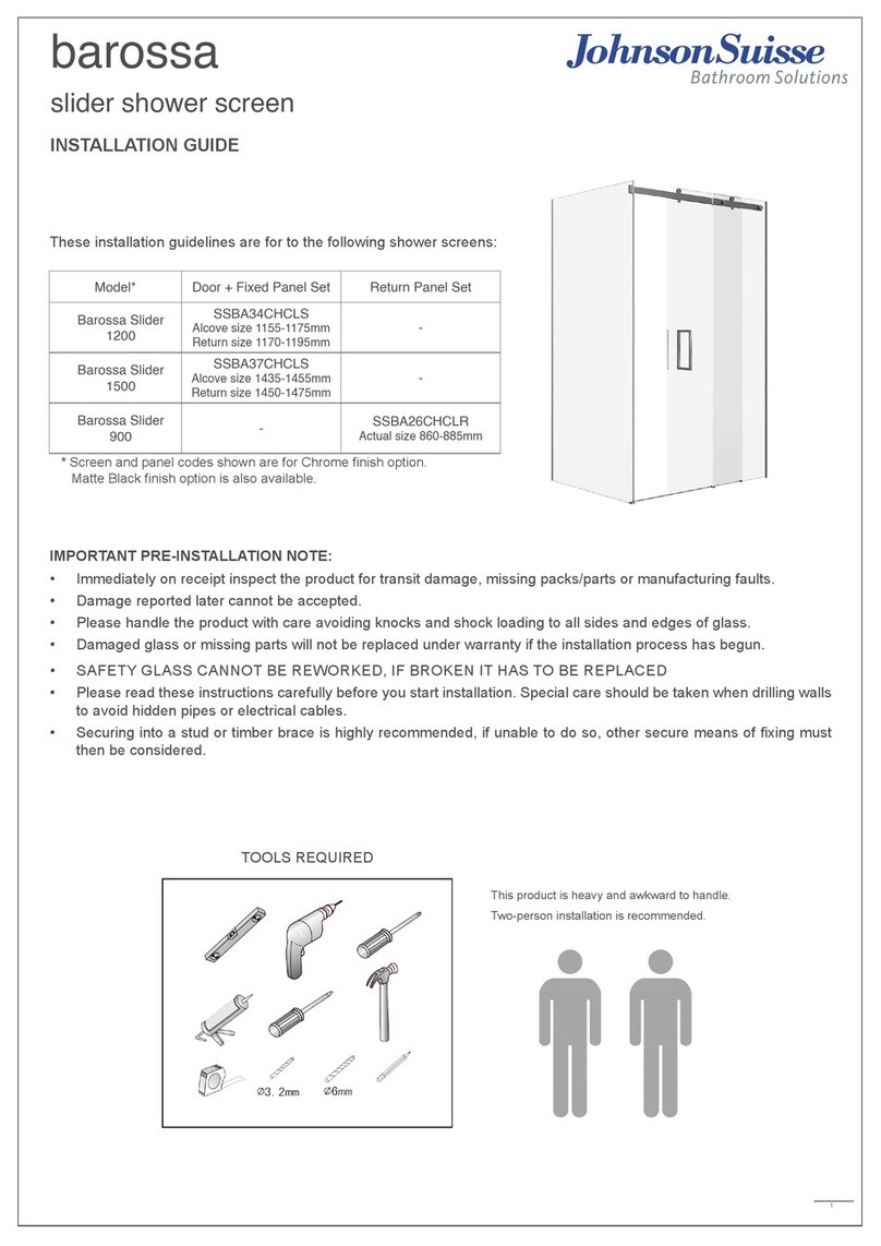
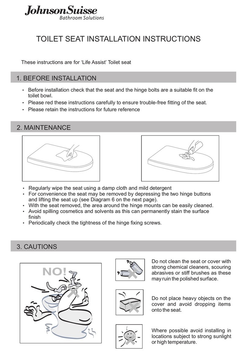
Please read and follow these step-by step instructions to ensure
correct installation
Operating environment
•When the outlet valve is installed there must be a
minimum gap of 25mm between the top of the overflow
tube and the Critical Level (CL) mark on the inlet valve.
Note that specifications and packaging
may change without notice
•Water temperature 2-45ºC
•Water pressure 0.02-1.0MPa
IMPORTANT
•Remove cistern lid
•Flush the cistern to
empty the water from the
tank
•Measure the water
depth in the tank
•Turn off water supply
Disconnect the water
supply hose
Unscrew the clip bracket
bolt and remove the valve
from the overflow tube •Fit the new inlet valve
to the overflow tube and
tighten the clip bracket
bolt
•Test flush
•Reconnect the water
supply hose
•Turn on supply and
check for connection
leaks
•Turn the screw adjustment
clockwise (anticlockwise) tpo
increase (decrease) the level
•Measure the water depth and
adjust to previous level
VALVE REPLACEMENT INSTRUCTIONS
1 2 3 45
1. Follow Steps 1, 2, 3 above
5. Re-assemble in reverse order
3. Remove the filter component
In some areas, it may be necessary to clean the
internal grit filter:
2. Unscrew the main nut to separate the inlet
connector from the valve body
4. Rinse under running water to remove any
dirt/debris
5. Re-assemble in reverse order
To remedy this, the diaphragm may be cleaned as follows:
3. Twist the plastic housing firmly anti-clockwise and remove it from
the valve body
If dirt/debris accumulates under the diaphragm it can prevent the valve
from closing properly
1. Follow Steps 1, 2, 3 above
2. Unclip the float arm from the top of the adjustment screw
4. Inspect rubber diaphragm and valve seat. Rinse under running
water to remove any dirt/debris
CLEANING THE FILTER CLEANING THE DIAPHRAGM
Filter
98
57
Overflow
tube
CRITICAL
LEVEL
Min 65
Max 145
WL
