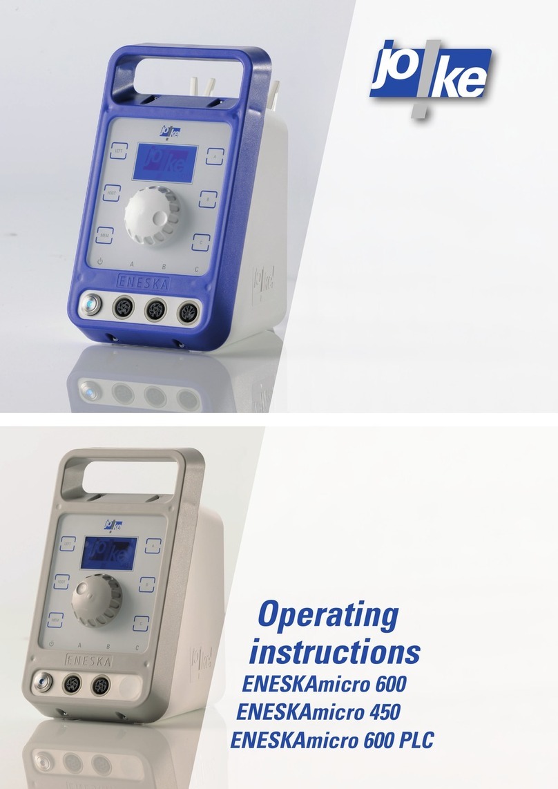
joke ENESKAmicro 600 User manual

Operating
instructions
ENESKAmicro 600
ENESKAmicro 450


33
Table of contents
1 Notes about these instructions ........................................4
2 Product overview ....................................................5
3 Technical specifications ..............................................5
4 Safety...............................................................8
Intended use ......................................................................8
General safety instructions..........................................................8
5 Controls and indicators ...............................................9
6 Initial startup .......................................................10
Replace the fuse (if necessary) .....................................................10
Connecting a motor cable ..........................................................11
Connecting a motor ...............................................................11
Connecting a handpiece ...........................................................12
Connecting the mains cable ........................................................12
Switching the unit on ..............................................................12
Setting the language (if necessary)..................................................13
7 Installing or changing a tool..........................................14
Compact SE, HT 60, HT 60 SMALL, HT 60 XL ..........................................14
HT 60 D6, HT 60-D6 CNC ...........................................................14
JEHG 400 / JHG 210 ...............................................................15
JEHR 500, JIR 310 .................................................................15
JERA 270, JBMH 300 N ............................................................15
JERA 270 S ......................................................................16
JIH 300 ..........................................................................16
JKC 345, JIC 390, JEKC 300, WE4-45, WE4-90 .........................................16
JMFC 300 S / 300 M ...............................................................17
8 Operation ..........................................................18
Switching the unit on and o .......................................................18
Choosing the direction of rotation ...................................................18
Choosing a motor .................................................................19
Setting the speed .................................................................19
Starting the motor.................................................................20
Stopping the motor ................................................................20
Calling up information about the unit ................................................21
9 Using foot mode.....................................................22
Switching foot mode on............................................................22
Fixing the speed ..................................................................22
10 Using the memory function (MEM) ....................................23
Saving settings ...................................................................23
Activating/deactivating settings ....................................................23
11 Setting a timer ......................................................24
12 Using a programmable logic controller (PLC)...........................25
Connecting the PLC ...............................................................25
Setting the PLC functions ..........................................................25

44
1
13 Changing the collet chuck ...........................................27
HT 60, HT 60 XL ...................................................................28
HT 60 D6, HT 60-D6 CNC ...........................................................28
HT 60 SMALL .....................................................................29
JEHG400/JHG210 .................................................................30
JEHR 500, JIR 310 .................................................................30
JERA 270, JBMH 300 N ............................................................31
JERA 270 S .......................................................................31
JIH 300 ..........................................................................32
JKC 345, JIC 390, JEKC 300, WE4-45, WE4-90 .........................................32
JMFC 300 S / 300 M ...............................................................32
14 Maintenance, care and disposal ......................................33
15 Troubleshooting.....................................................33
Notes about these instructions
These operating instructions enable the operator to correctly use, take care of and maintain the
ENESKAmicro Systems 450 or 600units. These operating instructions are part of the system and
must always be kept at hand at the place of use.
If the ENESKAmicro system is passed on to a third party then these operating instructions must
be passed on too.
Instructions which must be strictly observed to prevent hazards or damage are marked as fol-
lows:
Warning!
Warns of hazards that could result in serious injury or death.
Caution!
Warns of hazards that can lead to damage to objects.
For technical problems or other questions please contact our service department.

55
2
3
Product overview
C
B
A
LEFT
FOOT
MEM
A
B
C
3 4 5
1
2
Fig. 1
1 Collet chuck 4 Motor cable
2 Handpiece 5 ENESKAmicro control unit
3 Motor
You will find a comprehensive system overview in the JOKE surface treatment catalogue, in the
“Drive systems and handpieces” chapter.
Technical specifications
ENESKAmicro 450 control unit
Motor connections 2 connections for brushlessDC motors
Supply voltage 115 / 230V, 50 / 60Hz
Max. speed 45,000rpm
Power supply socket fuse 16A
Dimensions (W x H x D) 135 x 235 x 200mm
Weight 3.6kg
Ambient conditions 0 to +40°C
10% to 85% humidity
ENESKAmicro 600 control unit
Motor connections 2connections for brushlessDC motors
1 connection for carbon brush motors
Supply voltage 115 / 230V, 50 / 60Hz
Max. speed 60,000rpm
Power supply socket fuse 16A
Dimensions (W x H x D) 135 x 235 x 200mm
Weight 3.6kg
Ambient conditions 0 to +40°C
10% to 85% humidity

66
Approved motors Max.
speed
(rpm)
Handpiece -
motor con-
nection
Motor cable
ENESKAmicro Motor SE3 50,000 (-) ENESKAmicro S
ENESKAmicro Motor SE4 50,000 (+) ENESKAmicro S
ENESKAmicro COMPACT SE 50,000 COMPACT ENESKAmicro HT
ENESKAmicro COMPACT HT60 60,000 COMPACT ENESKAmicro HT
ENESKAmicro COMPACT HT60 SMALL 60,000 COMPACT ENESKAmicro HT
ENESKAmicro COMPACT HT60-XL 60,000 COMPACT ENESKAmicro HT
ENESKAmicro COMPACT HT60-D6 60,000 COMPACT ENESKAmicro HT
Micromotor JBM 50 HT 50,000 (+) JBM 50 S/EM
Micromotor JBM 50 S 50,000 (+) JBM 50 HT/EM
Micromotor JENK-250T 25,000 (-) JENK-250T/EM
Micromotor JENK-410S 40,000 (-) JENK-410S/EM
Micromotor JNK-261 (-) NCL-261
Micromotor JNK-351 (-) NCL-631
Marathon 3rd party motor 60,000 (+) / (-) SDE-BH60/EM
Approved
reduction gearbox
Max. speed
(rpm)
Speed reduction Connection
JRG 01 30,000 4 : 1 (-)
JERG 01 B 30,000 4 : 1 (+)
Approved adapters Max. speed
(rpm)
Function
JECN 01 T 35,000 Handpieces with a (-) connection can be con-
nected to motors with a (+) connection
Approved
extenders
Max. speed
(rpm)
Connection
JCN 01 35,000 (-)
Approved handpieces with a (+) connection Max. speed
(rpm)
JBS 400 belt grinder 15,000
DIPROFIL Di-Pro FXM-N, Mark II hand-held filing
machine 7,000 (strokes)
DIPROFIL FPM/ERJ, Mark II hand-held filing machine 7,000 (strokes)
DIPROFIL FPT/ER, Mark II hand-held filing machine 8,000 (strokes)
FMD/3-2/EM hand-held filing machine 7,800 (strokes)
JFMM 4 hand-held filing machine 7,800 (strokes)
JEHG 400 handpiece 30,000
DIPROFIL FMR/E mini hand-held filing machine 8,000 (strokes)
JN 48 mini hand-held filing machine 12,500 (strokes)
FMV/E cross-stroke handpiece 8,000 (strokes)

77
Approved handpieces with a (+) connection Max. speed
(rpm)
JEHR 500 quick-release handpiece 50,000 (continuous operation: 40,000)
JEKC 300 angled handpiece 20,000
JERA 270 angled handpiece 20,000
JERA 270 S angled handpiece 18,000
WE4-45 angled handpiece 30,000
WE4-90 angled handpiece 30,000
Approved handpieces with a (-) connection Max. speed
(rpm)
JBS 100 belt grinder 13,000
JIG 400 Filigree handpiece 40,000
DIPROFIL Di-Pro FXM-N, Mark II hand-held filing
machine 7,000 (strokes)
DIPROFIL FPM/ERJ, Mark II hand-held filing machine 7,000 (strokes)
DIPROFIL FPT/NR, Mark II hand-held filing machine 8,000 (strokes)
FMD/3-2 hand-held filing machine 7,800 (strokes)
JFMM 3 hand-held filing machine 7,800 (strokes)
JBMH 300 N handpiece 35,000
JHG 210 handpiece 27,000
JMFC 300 M miniature angled handpiece 15,000
JMFC 300 S miniature angled handpiece 15,000
DIPROFIL FMR/N mini hand-held filing machine 8,000 (strokes)
JN 38 mini hand-held filing machine 10,000 (strokes)
DIPROFIL FMV/N cross-stroke handpiece 8,000 (strokes)
JIH 300 quick-release handpiece 40,000
JIR 310 quick-release handpiece 40,000
JIC 390 angled handpiece 20,000
JKC 345 angled handpiece 20,000

88
4Safety
Intended use
ENESKAmicro systems are designed exclusively for grinding, milling, deburring and polishing
with the tools listed and approved in the JOKE catalogue.
ENESKAmicro systems may only be used with approved components and accessories (see
chapter3, Technical specifications).
The values specified in the technical specifications of the individual components must not be
exceeded when working with the ENESKAmicro system.
ENESKAmicro control units may only be used as described in these operating instructions. Any
other use or use going beyond this is considered improper use. The manufacturer will not be
liable for damage resulting from improper use.
General safety instructions
To avoid danger to persons and material damage, ALWAYS observe the following safety instruc-
tions:
• Only use ENESKAmicro systems in technically perfect condition.
• Always place the ENESKAmicro system control unit on a safe, non-slip surface and protect it
from contact with liquids.
• When working with the ENESKAmicro system, always wear safety glasses, gloves and hearing
protection.
• Always ensure sucient extraction of any dust particles that may arise.
• Do not leave the ENESKAmicro system unattended when switched on.
• Immediately rectify faults in the ENESKAmicro system yourself or have them rectified in ac-
cordance with these instructions.
• Do not make any changes, additions or modifications to the individual components of the ENE-
SKAmicro system.
• Never immerse the individual components of the ENESKAmicro system in water or other
liquids.
• Do not use the system outdoors.

99
5Controls and indicators
C
B
A
LEFT
FOOT
MEM
A
B
C
A
1
2
3
4
5
6
7
8
9
10
11
15
16
17
18 000 rpm
- A B C
t=1
18
19
20
23
22
141312
21
Fig. 2
1 Power switch 13 Connection B (BLDC - brushlessDC motor)
2 MEM button 14 Connection C (DC carbon brush motor; if
available)
3 FOOT button 15 Connection for a foot pedal or PLC
4 LEFT button 16 Fuse
5 Display 17 Mains plug connection
6 Handpiece rest (if available) 18 Speed display as ACTUAL value or %
7 Carrying handle 19 Speed indicator as bar
8 Motor buttonA 20 Information area:
Plugged-in motors and foot pedal
9 Motor button B 21 Display of timer function
10 Motor button C (if available) 22 On/o switch on motor (or handpiece)
11 Rotary control knob 23 Tool
12 ConnectionA (BLDC - brushlessDC motor)

1010
6Initial startup
Replace the fuse (if necessary)
The control unit is factory set to 230V and equipped with two 2A fuses. One of these two is
intended to be a spare. Two 4A fuses are also included.
Caution!
Only use the following fuses:
• Microfuse 5 x 20mm, T4L 250V for 115V
• Microfuse 5 x 20mm, T2L 250V for 230V
230
115
115
230
Fig. 3
3.
4.
230
230
2A
2A 180° 6.
115
230
5.
7.
115
230
8.
9. 4A
4A
A
230
230
2.
1.
1.
230
A
115
10.
115
230 V
115 V
Fig. 4

1111
Connecting a motor cable
Caution!
Always insert the cable carefully into the socket on the control unit and make sure that the con-
tacts and threads are not damaged.
• ConnectionA: BLDC - brushlessDC motor
• Connection B: BLDC - brushlessDC motor
• Connection C: DC carbon brush motor
MEM C
C
B
A
1.
2.
Fig. 5
Connecting a motor
Caution!
Always connect motor and cable carefully and make sure that the contacts and threads are not
damaged.
1.
2.
Fig. 6

1212
Connecting a handpiece
Caution!
Carefully push the motor and the handpiece together and make sure that the contacts, the motor
shaft, the handpiece coupling and the threads are not damaged. Always use the supplied tool.
If there is resistance before the thread is completely screwed in, first turn the handpiece’s collet
chuck manually until the coupling engages.
1.
2.
3.
Fig. 7 (example illustration)
Connecting the mains cable
2.
1.
Fig. 8
Switching the unit on
MEM
C
C
B
A
Fig. 9

1313
Setting the language (if necessary)
Action Shown in the display
2x
Call up the main menu
= ESC = XXXXXXXX =
-----------------------------------
- __________
- __________
- __________
= ESC = MAIN MENU =
Select language menu
= ESC = ___________ =
-----------------------------------
- XXXXXX
- __________
- __________
Language
Select language
= ESC = ___________ =
-----------------------------------
[C]=ESC[MEM]=Save
Deutsch
English
Francais
Cesky
Espania
>
(example)
MEM
Save language
= ESC = ___________ =
-----------------------------------
[C]=ESC
Deutsch
English
Francais
Cesky
Espania
>(example)
C
2x
Back to the start page
>
18 000 _____
- A B C
t=1

1414
Installing or changing a tool
Warning!
To avoid injuries caused by the tool turning unintentionally, only connect or change tools when
the control unit is switched o.
Warning!
To avoid injuries caused by tools coming loose, always insert the tools into the collet chuck as far
as they will go and also adjust the collet chuck on the JEHR 500, JIH 300 and JIR 310 handpieces.
Caution!
Thoroughly clean all parts before installing them.
If it should be necessary to change the collet chuck: see chapter13, "Changing the collet chuck".
Compact SE, HT 60, HT 60 SMALL, HT 60 XL
CLICK
1.
2.
CLICK
4.
3.
Fig. 10
HT 60 D6, HT 60-D6 CNC
4.
6.
5.
1.
2.
3.
Fig. 11
7

1515
JEHG 400 / JHG 210
1.
4.
2.
3.
6.
5.
Fig. 12
JEHR 500, JIR 310
CLICK 6.
3.
4.
1/5
5.
CLICK
1.
2.
Fig. 13
JERA 270, JBMH 300 N
3.
2.
4.
1x
1.
1x
Fig. 14

1616
JERA 270 S
1.
3.
2.
6.
5.
4.
Fig. 15
JIH 300
2.
1.
90°
3.
4. 1/5
5.
6.
90°
Fig. 16
JKC 345, JIC 390, JEKC 300, WE4-45, WE4-90
1.
1x 2.
3.
4.
1x
6.
5.
Fig. 17

1717
JMFC 300 S / 300 M
1.
2.
3.
4.
Fig. 18

1818
Operation
Switching the unit on and o
MEM
C
C
B
A
MEM
C
C
B
A
Fig. 19
Choosing the direction of rotation
Anti-clockwise (LEFT) rotation can only be selected if the handpiece is approved for two direc-
tions of rotation.
OptionA:
C
B
A
LEFT
FOOT
MEM
A
B
C
18 000 rpm
- A B C
t=1
LEFT
LEFT
Fig. 20
Option B:
2x
Fig. 21
8

1919
Choosing a motor
Several motors can be connected to the control unit at the same time, but only one motor can be
used at a time.
The motor that was last connected to or was used with the control unit will automatically be
selected. The motor buttonA, B or C belonging to this motor will flash. If necessary, press motor
buttonA, B or C to select another motor.
Setting the speed
Warning!
To avoid injury and damage to components due to excessive speeds, never exceed the maximum
permissible speed of the connected components and accessories.
Caution!
To avoid damage to the handpiece, reduce the speed if the tool protrudes by more than 13mm.
Tool protrusion Speed
13mm to 20mm 50% of the approved speed
21mm to 25mm 30% of the approved speed
26mm to 50mm 10% of the approved speed
LEFT
FOOT
MEM
A
B
C
18 000 rpm
- A B C
t=1
+-
Fig. 22
Releasing the block at 50,000rpm:
ENESKAmicro 600 control units with COMPACT HT60 and HT60 small motors:
»Set 50,000rpm.
»Press the rotary control knob.
The higher speed range will be enabled and can be set with the rotary knob (max. 60,000rpm).

2020
Starting the motor
A
p
m
B
B C
C
A B C
Fig. 23
Stopping the motor
A
p
m
B
B C
C
A B C
Fig. 24
Other manuals for ENESKAmicro 600
2
This manual suits for next models
1
Table of contents
Other joke Control Unit manuals