joke ENESKArecoat 85 User manual

Operating
instructions
ENESKArecoat 85


33
Table of contents
1 Notes about these instructions . . . . . . . . . . . . . . . . . . . . . . . . . . . . . . . . . . . . . . . . 5
2 Product overview . . . . . . . . . . . . . . . . . . . . . . . . . . . . . . . . . . . . . . . . . . . . . . . . . . . . 5
3 Scope of delivery of ENESKArecoat 85 (order no. 0 700 300) . . . . . . . . . . . . . . . 6
4 Technical specifications for control unit . . . . . . . . . . . . . . . . . . . . . . . . . . . . . . . . 6
5 Safety. . . . . . . . . . . . . . . . . . . . . . . . . . . . . . . . . . . . . . . . . . . . . . . . . . . . . . . . . . . . . . . 7
Intended use . . . . . . . . . . . . . . . . . . . . . . . . . . . . . . . . . . . . . . . . . . . . . . . . . . . . . . . . . . . . . . . . . . . . . . 7
General safety instructions. . . . . . . . . . . . . . . . . . . . . . . . . . . . . . . . . . . . . . . . . . . . . . . . . . . . . . . . . . 7
6 Controls and indicators . . . . . . . . . . . . . . . . . . . . . . . . . . . . . . . . . . . . . . . . . . . . . . . 8
7 The function of the signal sounds . . . . . . . . . . . . . . . . . . . . . . . . . . . . . . . . . . . . . . 9
8 Function of the LED display strip . . . . . . . . . . . . . . . . . . . . . . . . . . . . . . . . . . . . . . . 9
9 Functions of the signal LED on the handpiece . . . . . . . . . . . . . . . . . . . . . . . . . . 10
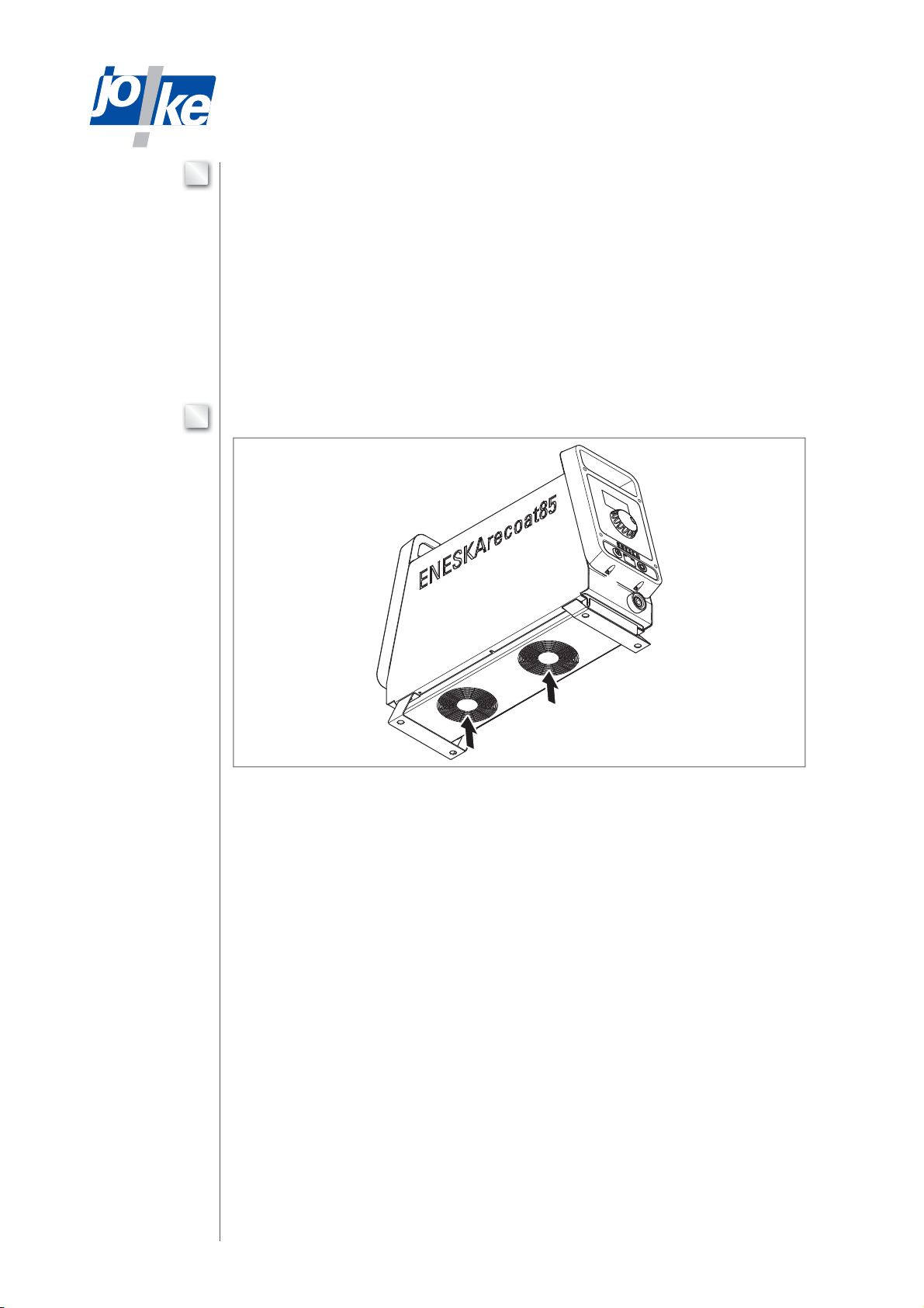
10 Function of the ventilation. . . . . . . . . . . . . . . . . . . . . . . . . . . . . . . . . . . . . . . . . . . . 10
11 Calling up the menu and navigating . . . . . . . . . . . . . . . . . . . . . . . . . . . . . . . . . . . 11
12 Commissioning . . . . . . . . . . . . . . . . . . . . . . . . . . . . . . . . . . . . . . . . . . . . . . . . . . . . . 11
Connecting a handpiece . . . . . . . . . . . . . . . . . . . . . . . . . . . . . . . . . . . . . . . . . . . . . . . . . . . . . . . . . . . 11
Connecting the ground cable . . . . . . . . . . . . . . . . . . . . . . . . . . . . . . . . . . . . . . . . . . . . . . . . . . . . . . . 12
Fitting/changing the electrode . . . . . . . . . . . . . . . . . . . . . . . . . . . . . . . . . . . . . . . . . . . . . . . . . . . . . . 13
Connecting the mains cable . . . . . . . . . . . . . . . . . . . . . . . . . . . . . . . . . . . . . . . . . . . . . . . . . . . . . . . . 14
Switching the unit on . . . . . . . . . . . . . . . . . . . . . . . . . . . . . . . . . . . . . . . . . . . . . . . . . . . . . . . . . . . . . . 14
Setting the language (if necessary). . . . . . . . . . . . . . . . . . . . . . . . . . . . . . . . . . . . . . . . . . . . . . . . . . 14
13 Connecting the foot pedal (optional). . . . . . . . . . . . . . . . . . . . . . . . . . . . . . . . . . . 15
14 Operation . . . . . . . . . . . . . . . . . . . . . . . . . . . . . . . . . . . . . . . . . . . . . . . . . . . . . . . . . .15
Pretreating surfaces . . . . . . . . . . . . . . . . . . . . . . . . . . . . . . . . . . . . . . . . . . . . . . . . . . . . . . . . . . . . . . 15
Switching the unit on . . . . . . . . . . . . . . . . . . . . . . . . . . . . . . . . . . . . . . . . . . . . . . . . . . . . . . . . . . . . . . 16
Setting parameters. . . . . . . . . . . . . . . . . . . . . . . . . . . . . . . . . . . . . . . . . . . . . . . . . . . . . . . . . . . . . . . . 16
Calibration . . . . . . . . . . . . . . . . . . . . . . . . . . . . . . . . . . . . . . . . . . . . . . . . . . . . . . . . . . . . . . . . . . . . . . . 18
Processing the workpiece . . . . . . . . . . . . . . . . . . . . . . . . . . . . . . . . . . . . . . . . . . . . . . . . . . . . . . . . . 18
Stopping the handpiece. . . . . . . . . . . . . . . . . . . . . . . . . . . . . . . . . . . . . . . . . . . . . . . . . . . . . . . . . . . . 20
Switching the unit o . . . . . . . . . . . . . . . . . . . . . . . . . . . . . . . . . . . . . . . . . . . . . . . . . . . . . . . . . . . . . . 20
Polishing the coating (if necessary) . . . . . . . . . . . . . . . . . . . . . . . . . . . . . . . . . . . . . . . . . . . . . . . . . 20
15 Using the memory function (MEM) . . . . . . . . . . . . . . . . . . . . . . . . . . . . . . . . . . . . 21
Saving settings . . . . . . . . . . . . . . . . . . . . . . . . . . . . . . . . . . . . . . . . . . . . . . . . . . . . . . . . . . . . . . . . . . . 21
Activating/deactivating settings . . . . . . . . . . . . . . . . . . . . . . . . . . . . . . . . . . . . . . . . . . . . . . . . . . . . 21
16 Calling up device information . . . . . . . . . . . . . . . . . . . . . . . . . . . . . . . . . . . . . . . . 22
17 Setting the signal tone and LEDs . . . . . . . . . . . . . . . . . . . . . . . . . . . . . . . . . . . . . . 22
18 Application notes . . . . . . . . . . . . . . . . . . . . . . . . . . . . . . . . . . . . . . . . . . . . . . . . . . . 22
Punching technology . . . . . . . . . . . . . . . . . . . . . . . . . . . . . . . . . . . . . . . . . . . . . . . . . . . . . . . . . . . . . . 22
Bending and pressing . . . . . . . . . . . . . . . . . . . . . . . . . . . . . . . . . . . . . . . . . . . . . . . . . . . . . . . . . . . . . 23
Extrusion. . . . . . . . . . . . . . . . . . . . . . . . . . . . . . . . . . . . . . . . . . . . . . . . . . . . . . . . . . . . . . . . . . . . . . . . . 23
Cold forming of screws, nuts, bolts, rivets, etc. . . . . . . . . . . . . . . . . . . . . . . . . . . . . . . . . . . . . . . . 23
Synthetic resin and duroplastic injection moulds, rubber moulding . . . . . . . . . . . . . . . . . . . . . . 23
Die casting technique . . . . . . . . . . . . . . . . . . . . . . . . . . . . . . . . . . . . . . . . . . . . . . . . . . . . . . . . . . . . . 23
Processing of wood and synthetic fibre boards . . . . . . . . . . . . . . . . . . . . . . . . . . . . . . . . . . . . . . . 24

44
19 Firmware update . . . . . . . . . . . . . . . . . . . . . . . . . . . . . . . . . . . . . . . . . . . . . . . . . . . . 25
Doing a firmware update. . . . . . . . . . . . . . . . . . . . . . . . . . . . . . . . . . . . . . . . . . . . . . . . . . . . . . . . . . . 25
Possible errors during a firmware update . . . . . . . . . . . . . . . . . . . . . . . . . . . . . . . . . . . . . . . . . . . . 26
20 Maintenance, care and disposal . . . . . . . . . . . . . . . . . . . . . . . . . . . . . . . . . . . . . . 26
Replacing the filter mat (if necessary) . . . . . . . . . . . . . . . . . . . . . . . . . . . . . . . . . . . . . . . . . . . . . . . 26
Notes on the E-Check according to DGUV V3 . . . . . . . . . . . . . . . . . . . . . . . . . . . . . . . . . . . . . . . . . 26
21 Troubleshooting and fixing faults . . . . . . . . . . . . . . . . . . . . . . . . . . . . . . . . . . . . . 27
Error . . . . . . . . . . . . . . . . . . . . . . . . . . . . . . . . . . . . . . . . . . . . . . . . . . . . . . . . . . . . . . . . . . . . . . . . . . . . 27
Faults. . . . . . . . . . . . . . . . . . . . . . . . . . . . . . . . . . . . . . . . . . . . . . . . . . . . . . . . . . . . . . . . . . . . . . . . . . . . 28
22 Declaration of Conformity . . . . . . . . . . . . . . . . . . . . . . . . . . . . . . . . . . . . . . . . . . . . 29

55
Notes about these instructions
These operating instructions enable the operator to correctly use, take care of and maintain the
ENESKArecoat 85 carbide coating system. These operating instructions are part of the system
and must always be kept at hand at the place of use. If the system is passed on to a third party
then this operating manual must be passed on too.
To avoid injury and damage to property, read these instructions before performing any work
with the system!
Instructions which must be strictly observed to prevent hazards or damage are marked as
follows:
Caution!
Warns of hazards that can lead to injuries.
Attention!
Warns of hazards that can lead to damage to objects.
For technical problems or other questions please contact our service department.
Product overview
USB
START
FOOT
MEM
PAR 1
PAR 2
ESC
3
4
5
67
1
2
Fig. 1
1 Control unit with mains cable 5 Electrodes
2 Vib85 application handpiece with hand-
piece cable incl. welding and control
cable plug
6 Screwdriver
3 Spare screw 7 Ground cable with welding cable plug and
contact magnet
4 Clamping element
The ENESKArecoat 85 carbide coating system operates according to the principle of electro-dis-
charge machining. A carbide electrode is attached to the positive pole of a DC circuit. It is made
to vibrate in the Vib85 application handpiece. The workpiece is connected to the negative pole.
During the brief contact pulse between the workpiece and the electrode, the electrode is briefly
overheated by the flowing current to such an extent that, during the discharge, carbide particles
from the electrode are entrained and fuse to the workpiece surface.
1
2

66
Scope of delivery of ENESKArecoat 85 (order no. 0 700 300)
• 1 x control unit with mains cable set for Germany, Switzerland, United Kingdom and Europe
(order no. 0 700 301)
• 1 x Vib85 handpiece with cable package (order no. 0 700 302)
• 1 x ground cable with plug and contact magnet (order no. 0 700 351)
• 1 x set of clamping elements for carbide electrodes, incl. spare screws and screwdriver
(order no. 0 700 060)
• 1 x set of carbide electrodes (order no. 0 700 034)
Optional:
• 1 x foot pedal (order no. 0 700 360)
• As delivered, a sticker is attached to the rotary control. This indicates that the rotary control
must be pressed twice to call up the main menu.
This can be removed after initial start-up.
Technical specifications for control unit
476135
413
221
321
START
FOOT
MEM
PAR 1
PAR 2
ESC
USB
Fig. 2
Connections
1 connection for handpiece control cable
1 connection for electrode cable
1 connection for ground cable
1 connection for power supply unit
1 USB connection
Supply voltage 90–230V~ (50/60Hz)
Rated power P_max 150VA
Rated current 1.3A / 0.65A
Maximum hardness of the layer 82 HR 30 N
Vibration frequency 120Hz
Weight 10kg
3
4

77
Approved handpieces Vib85
Weight of handpiece incl. connection cable 0.84kg
Working lamp in handpiece 4 LEDs, 5000K
Ambient conditions +10°C to +40°C
10% to 85% humidity
Noise pressure level < 70dB (A)
Approved carbide electrodes,
length 50mm
Round: Ø 1.0mm, Ø 1.3mm, Ø 1.8mm, Ø 2.3mm, Ø 3.0mm,
Ø 4.0mm
Square: 1.1mm, 1.6mm, 2.1mm
Triangular: 1.95mm
Approved foot pedal F85 foot pedal
Manufacturer’s mark and address, type designation, CE marking and serial number are located
on the nameplate on the rear of control units, or on the housing, depending on the handpiece.
The nameplate for the control unit also states the rated voltage (U_rated), the rated current
(I_rated), the rated power (P_rated) and the frequency (F_ultrasonic). It also indicates that the
device is grounded and must not be disposed of in household waste.
Accessories and the spare parts list are available online at www.joke-technology.de.
Safety
Intended use
The system is intended exclusively for applying carbide coatings to metallic surfaces. The
applied carbide layer increases the wear resistance of the coated workpiece without aecting
the qualities of the base material.
The unit may only be used with approved components and accessories (see section4, Technical
specifications).
The values specified in the technical specifications for the individual components must not be
exceeded when using the system.
Work on and with the unit may only be carried out by qualified, trained and authorised personnel.
The control unit may only be used as described in these operating instructions. Any dierent or
additional use is considered improper. The manufacturer will not be liable for damage resulting
from improper use.
General safety instructions
To avoid danger to persons and material damage, ALWAYS observe the following safety
instructions:
• Due to its design and use, increased vibrations and noise occur in the vicinity of the hand-
piece. According to the EU Directive 2002/44/EC, a new workplace assessment may have to be
performed.
• Only use the system in technically perfect condition.
• Always place the control unit on a safe, non-slip surface and protect it from contact with
liquids.
• Lay the mains cable so that it is easily accessible and can be disconnected from the power
supply easily.
• When working with the system, always wear safety glasses, gloves and hearing protection.
• Never disconnect the handpiece from the control unit while it is switched on!
• Always switch o the control unit when the system is not in use.
• Do not use the system if display and signal lamps are defective.
• Always make sure that the device’s ventilation slots are free (see also chapter 9).
• Do not leave the system unattended when switched on.
• Switch o and secure the control unit immediately in the event of malfunctions. In the event
5

88
of faults, rectify them immediately as described in these instructions or arrange for them to be
rectified.
• Do not make any changes, additions or modifications to the individual components of the
system.
• Refrain from any operation that could compromise safety.
• Never immerse the individual components of the system in water or other liquids.
• Do not use the system outdoors.
Controls and indicators
USB
START
FOOT
MEM
PAR 1
PAR 2
ESC
54VCHARGE
Energy
CYCL
HST: Vib85
Vibr 120Hz 36%
175
SMOOTH
mWs
Cyl:
Off
12
3
5
4
6
7
8
9
10
11
12
13
14
15
25
24
26
32
31
30
29
27 21 20222328
12
18
19
17
16
Fig. 3
1 Ground socket 17 Mains plug connection
2 Electrode socket 18 Foot pedal connection (IO socket, 8-pin,
M12)
3 Connection socket for handpiece (8-pin) 19 Signal LED on handpiece
4 USB connection 20 Button of the handpiece
5 Power switch 21 Handpiece
6 MEM button 22 Clamping element
7 FOOT button 23 Electrode
8 Display 24 Display of coating energy (charging
voltage)
9 START button 25 Status display charge accumulator 1
10 Carrying handle 26 Status display charge accumulator 2
11 LED strip 27 Display number of cylinders
12 PAR1 button 28 Information on the connected handpiece
13 PAR2 button 29 Information on interval coating
14 Rotary pushbutton 30 Display of vibration intensity
15 ESC button 31 Display of coating quality (smooth or
rough)
16 Nameplate 32 Energy display
6

99
The function of the signal sounds
2 brief sounds
• After calibration: Device is ready to use
• Settings accepted e.g. after saving
1 long sound
• Device error or faulty operation
Troubleshooting or device restart required
Function of the LED display strip
START
FOOT
MEM
PAR 1
PAR 2
ESC
US
Fig. 4
LED strip Colour Type of display Meaning
Top Blue Pulsing Handpiece is connected
Blue-white Movement towards the
centre
Handpiece is switched on and operating
with proper ground contact.
Orange Movement towards the
centre
Handpiece is switched on, but has no
ground contact
Red Movement towards the
centre
The pressure with which the workpiece
is pressed during operation is too high.
Bottom White LED runs from left to right
summing up during cali-
bration.
The pressure with which the workpiece
is pressed during operation is optimal.
Green LED runs from left to right
summing up during cali-
bration.
Mechanical zero point detected and
adjusted.
Right Green, yellow,
red
Rising from green to red Display of device temperature in control
unit
Top, bottom Red Lights Device error or faulty operation
Red Lights and buttons flash
simultaneously
Serious device fault or dangerous oper-
ating error, restart required
All White (right,
left), Blue (top,
bottom)
Lights Device starting or important information
in display
Colourful Flashing and motion Animation running
7
8

1010
Functions of the signal LED on the handpiece
• LED does not light up:
The handpiece is not connected or a menu has been called up on the control unit’s display.
• LED flashes green:
The handpiece is activated and waiting.
• LED lights up green continuously:
The handpiece is in operation.
• LED lights up orange:
The handpiece is in operation, but there is no contact to ground.
• LED lights up red:
The handpiece is in operation, but is pressed onto the workpiece with too much pressure.
Function of the ventilation
USB
Fig. 5
The ventilation serves to prevent overheating. Air is drawn into the control unit through the slots
on the underside of the control unit. The air is guided through the control unit and blown out
again at the lettering on both sides.
Always keep the unit’s ventilation slots clear to prevent damage from overheating.
9
10

1111
Calling up the menu and navigating
When the menu is opened, the handpiece automatically switches o.
2x Press the rotary
control knob twice:
• Open main menu
= ESC = MENU =
-----------------------------------
- __________________
- __________________
- __________________
- __________________
- __________________
[C]=ESC
Fig. 6
Press the rotary control
knob once:
• Call up the selected
menu
• Confirm selection
• Activate a value to be
able to change it
Turn the rotary control knob
clockwise
• Selection bar will jump
one position down
• Activated value counts
up
Fig. 7
Turn the rotary control knob
anticlockwise
• Selection bar will jump
one position up
• Activated value counts
down
MEM
Press the MEM button
• Save the setting just
made
Fig. 8
ESC
Press the ESC button
• Escape / Back [ESC]
• Return to previous menu
ESC
2-3x
Press the ESC key
multiple times
• Return to standard
display
Fig. 9
Commissioning
Connecting a handpiece
Attention!
To avoid serious damage to the system, only connect the handpiece to the control unit or remove
it from the control unit when the system is switched o!
Attention!
Always insert the control cable plug into the socket of the control unit so that the base on the
plug fits into the guide of the socket and the red dots on the plug and socket are aligned. Do not
damage the contacts while doing so!
Attention!
Always insert the welding cable plug into the socket of the control unit so that the socket on the
plug fits into the guide of the socket. Then turn the plug to secure it in the socket.
11
12

1212
USB
START
FOOT
MEM
PAR 1
PAR 2
ESC
1.
2.
3.
Fig. 10
Connecting the ground cable
Attention!
During coating, very high currents flow between the electrode and the workpiece. To keep
parasitic inductance as low as possible, lay all cables as parallel as possible and do not coil the
cables.
Attention!
Always insert the welding cable plug into the socket of the control unit so that the socket on the
plug fits into the guide of the socket. Then turn the plug to secure it in the socket.
Attention!
If the workpiece is too small to attach the contact magnet to it, clamp the workpiece in a suitable
vice and attach the contact magnet to this.
USB
START
FOOT
MEM
PAR 1
PAR 2
ESC
2.
1.
3.
Fig. 11

1313
Fitting/changing the electrode
The choice of electrode depends on the size and shape of the surface to be coated. Workpieces
with simple shapes can be coated with a 1.6 or 2.1mm square electrode. Dies with complicated
internal shapes or small holes are coated with the appropriate round, 3-sided or 4-sided elec-
trode. For small holes of less than Ø 1.2mm, the round 1mm electrode is ground at least 0.2mm
thinner than the hole to be coated on a diamond or silicon grinding wheel.
Caution!
To avoid injuries caused by the hot surface of the tool, only connect or change tools when the
control unit is switched o.
Caution!
To avoid injury from tools coming loose, always tighten the tools carefully and regularly check the
fit of the tool.
Attention!
To avoid damage to the components,
• thoroughly clean all parts before installing them and
• use only the screwdriver supplied.
1.
2.
3.
4.
6.
5.
10
Fig. 12

1414
Connecting the mains cable
Lay the mains cable so that it is not under tension and does not obstruct anyone. Do not place
anything on the cable.
2. 1.
Fig. 13
Switching the unit on
START
FOOT
MEM
PAR 1
PAR 2
ESC
USB
START
FOOT
MEM
PAR 1
PAR 2
ESC
USB
START
FOOT
MEM
PAR 1
PAR 2
ESC
USB
54VCHARGE
Energie
CYCL
HST: Vib85
Vibr 120Hz 36%
175
GLATT
mWs
Zyl:
Off
12
2x
ENESKA recoat85
Fig. 14
Setting the language (if necessary)
Step 1 Step 2 Step 3 Step 4
2x
MEM
ESC
2x
Open main menu Select “Sprache/Lan-
guage”
Choose the language
and save your choice
Back to the standard
display
= ESC = MENU =
-----------------------------------
- Sprache/Language
- G-Info
- Summer+LED
- Firmware Update
[C]=ESC
= ESC = Language =
-----------------------------------
> Deutsch
English
Francais
[MEM]=SAVE [C]=ESC

1515
Connecting the foot pedal (optional)
Attention!
To avoid serious damage to the system, only connect the foot pedal to the control unit or remove
it from the control unit when the system is switched o!
With a foot pedal, you can switch the handpiece on and o using your foot during operation.
The foot pedal performs the same function as the button on the handpiece. The button on the
handpiece is automatically deactivated when the foot pedal is connected. Only the settings for
the working light on the handpiece are retained.
Lay the foot switch mains cable so that it is not under tension and does not obstruct anyone.
Do not place anything on the cable.
MEM ESC
USB
MEM ESC
USB
1.
4.
2.
A
3.
Fig. 15
Operation
Attention!
The workpiece must be metallically clean and bright. It must not have any scaling or other
impurities, as the coating will then not be reliably absorbed and will not adhere securely.
The magnet must also always be clean to ensure good electrical contact.
Attention!
Before each use of the unit, check that all contact connections are clean and tight.
Degrease perfectly bright steel surfaces well before coating.
Pretreating surfaces
Coating can only be successful if the coating is applied to a metallically clean steel surface.
The following methods can be used to clean the workpiece:
• Fine blasting: achieves the deepest diusion of the tungsten carbide molecules in the base
material and the highest adhesion of the coating.
• Grinding: grind over the contour to be coated or at least clean it with abrasive cloth or diamond
files and then degrease it.
Do not use acidic cleaning agents! These do not neutralize suciently, continue to act under the
coating and can destroy the coating.
14
13

1616
Switching the unit on
Attention!
To avoid damage to the device,
• before switching on, equip the handpiece with an electrode and do not work with the tool until
the automatic calibration has been completed and the upper LED bar pulses blue.
START
FOOT
MEM
PAR 1
PAR 2
ESC
USB
START
FOOT
MEM
PAR 1
PAR 2
ESC
USB
START
FOOT
MEM
PAR 1
PAR 2
ESC
USB
54VCHARGE
Energie
CYCL
HST: Vib85
Vibr 120Hz 36%
175
GLATT
mWs
Zyl:
Off
12
2x
ENESKA recoat85
Fig. 16
Setting parameters
Attention!
To avoid damage to tools or the workpiece:
• always start with the standard setting (vibration intensity 60% and charging voltage 48V) and
then adjust both as required and
• for high power settings, only use tools designed for this purpose!
The following parameters can be set with the “PAR1” button:
»Coating energy: 30–54V
»Vibration intensity: 0–100%
54VCHARGE
Energy
CYCL
HST: Vib85
Vibr 120Hz 0%
175
SMOOTH
mWs
Cyl:
Off
12
+–
PAR 1
54VCHARGE
Energy
CYCL
HST: Vib85
Vibr 120Hz 36%
175
SMOOTH
mWs
Cyl:
Off
12
+–
30-54 V
0-100 %
Fig. 17

1717
The following parameters can be set with the “PAR2” button:
»Operating mode
Operation with 1 cylinder or with 2 cylinders; the setting depends on the electrode thickness
and the desired coating strength.
»Application type
SMOOTH/ROUGH
With the “ROUGH” selection, the ignition point for the discharge current occurs before or
while the electrode is touching the workpiece. As a result, the drops are mechanically
separated and the surface is coated more roughly.
With the “SMOOTH” selection, the ignition for the discharge takes place shortly after the
electrode leaves the workpiece again. The surface is coated more smoothly.
»Phi_0:
This parameter cannot be changed.
If a value is displayed, it is the correction value between the electrical and mechanical ignition
timing.
NOCAL indicates that no calibration is taking place or has taken place.
»Interval
0.5–30 seconds; intervals are used for short, repetitive coating operations. One second
corresponds to 120 strokes.
»Int-Pause
0–20s; pause between intervals.
54VCHARGE
Energy
CYCL
HST: Vib85
Vibr 100Hz 0%
175
SMOOTH
mWs
Cyl:
Off
12
Application type
Phi_0
Operating mode
Int-Pause
[Press]=Change
Interval 2,0 s
1-Cyl
smooth
---
AUTO
+–
0-150
1-Cyl/ 2-Cyl
PAR 2
+–
Application type
Phi_0
Operating mode
Int-Pause
[Press]=Change
Interval 2,0 s
1-Cyl
smooth
---
AUTO
0-20 s
Application type
Phi_0
Operating mode
Int-Pause
[Press]=Change
Interval 2,0 s
1-Cyl
smooth
---
AUTO
+–
Application type
Phi_0
Operating mode
Int-Pause
[Press]=Change
Interval 2,0 s
1-Cyl
smooth
---
AUTO
+–
MEM
MEM
MEM
MEM
SMOOTH/ROUGH
ESC
54VCHARGE
Energy
CYCL
HST: Vib85
Vibr 100Hz 0%
175
smooth
mWs
Cyl:
Off
12
Fig. 18

1818
Calibration
The mechanical zero point depends on various factors and varies according to energy and
vibration intensity, diameter and length of the electrode as well as pressure of the electrode and
guide angle to the workpiece.
Always adjust the mechanical zero point at the start of work, after changing settings, and as
needed.
START
>5 sec
20 sec
Fig. 19
Processing the workpiece
Attention!
To avoid injuries, do not touch the metal part of the handpiece, the clamping element or the
electrode while working!
A B
Fig. 20

1919
Fig. 21
20°
Fig. 22
Hold the handpiece with one hand and support your hand as much as possible. Press the
electrode lightly against the workpiece at an angle of 15–20° to the surface to be coated.
If the electrode touches the opposite edge in this inclined position in the case of small holes or
profiles, you can also hold the electrode parallel to the hole.
Process the surface of the workpiece slowly and evenly until the coating is as fine and homoge-
neous as possible. An optimum coating is matt grey and fine-pored.
Caution!
Under continuous operation and with a strong energy output, the electrode becomes warmer
than 42°C and its holder heats up. This then leads to a slow heating of the entire handpiece.
• If the handpiece becomes too warm, switch o the handpiece and allow it to cool down.
• For continuous operation, work alternately with two handpieces.
Attention!
If the electrode glows, the coating becomes defective. Sparking also leads to a poor result, as
the melted carbide splatters and cannot be deposited on the workpiece.
• If the clamped electrode starts to glow or sparks fly, reduce the coating energy.
In the case of very fine moulded parts, coating in stages is advantageous because it can some-

2020
what dampen the fusion penetration on exposed areas.
If a finely lapped surface is to be achieved, you should first apply a relatively thick coat, followed
by a thinner second coat.
Stopping the handpiece
A B
Fig. 23
Switching the unit o
USB
Fig. 24
Polishing the coating (if necessary)
Wet the applied coating with abrasive file oil. Then smooth the applied coating with a dia-
mond-tipped tool in rotating movements. Next, clean the coating with a cleaning agent
(JOKE X 73016 ).
To obtain a very fine surface, polish the coating further with a wooden stick and a 20μm diamond
lapping paste. Clean the surface. Then polish the coating further with a wooden stick and a 10μm
diamond lapping paste. Machine round workpieces as described on a high-speed rotating lathe.
This manual suits for next models
1
Table of contents
Other joke Welding System manuals
Popular Welding System manuals by other brands

Sealey
Sealey 140XT instructions

Murex
Murex Tradesmig 283 operating manual

Leister
Leister Uniplan Wedge operating instructions

Rossi Welders
Rossi Welders WLDMIG195RSSACAA user manual

Air Liquide
Air Liquide PRESTOTIG 160 PFC Safety instruction for use and maintenance

Miller
Miller Cool Runner 3CS OM-230 161 F owner's manual