4.1 Mounting
For the various mounting positions of the FIXTURE(standing on the floor, sideways or hanging different
accessories kits are available.
Through this a safe and firm installation is assured.
You’ll find special connectors on the bottom side of the system which are put to use here.
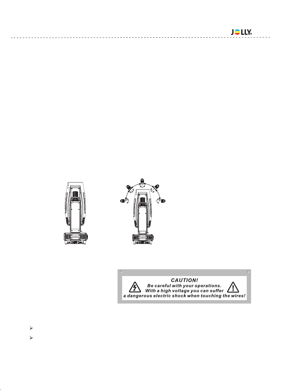
4.2 Installing the Clamps
Please consider the respective national norm s during the Installation!The installation must only be car-
ried out by an authorized dealer!
The installation of the projector has to be built and constructed in a way that it can hold 10 times the wei-
ght for 1 hour without any harming deformation.
The installation must always be secured with a secondary safety attachment, e.g.an appropriate catch
net.This secondary safety attachment must be constructed in a way that no part of the installation can
fall if the main attachment fails.
When servicing the fixture staying in the area below the installation place,on bridges,under high working
places and other endangered areas is forbidden.
The operator has to make sure that safety-relating and machine-technical installations are approved by
an expert before taking into operation for the first time and after changes before taking into operation an-
other time.
The operator has to make sure that safety-relating and machine-technical installations are approved by
an expert after every four year in the course of an acceptance test.
The operator has to make sure that safety-relating and machine-technical installations are approved by
a skilled person once a year.
The projector should be installed outside areas where persons m ay walk by or be seated.
Important!Overhead rigging requires extensive expering CE,including (but not limited to)calculating
working load limits, installation material being used, and periodic safety inspection of all installation ma-
terial and the projector. If you lack these qualifications, do not attempt the installation yourself, but inste-
ad use a professional structural rigger. Improper installation can result in bodilyinjury and or damage to
property.
The projector has to be installed out of the reach of people.
If the projector shall be lowered from the ceiling or high joists, professional trussing system s have
to be used. The projector must never be fixed swinging freely in the room .
Caution Projectors may cause severe injuries when crashing down! If you have doubts concerning the
safety of a possible installation, do not install the projector!
Before rigging make sure that the installation area can hold a minim um point load of 10 times the
projector s weight.
4.Rigging the fixture
- 4 -
Pay attention to the regulations of CE.
Installation by qualified staff to complete.
If this device will be operated in any way different to the one described in this manual, the product may suffer
damages and the guarantee becomes void.Furthermore, any other operation may lead to dangers like short-circ-
uit,burns, electric shict,burns due to ultraviolet radiation,lamp explosion,crash etc.