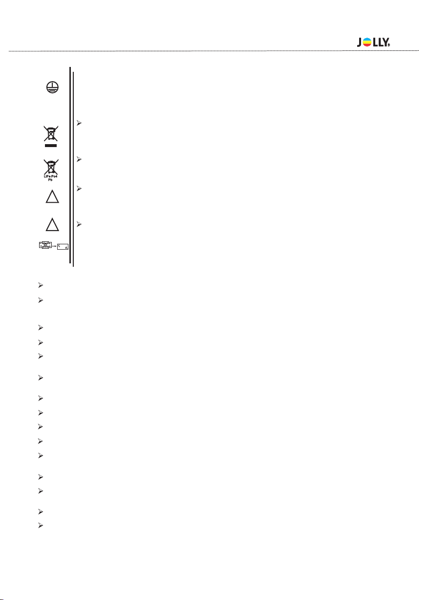
Jolly A-5 Spot User manual

USER MANUAL
5
Version:1.0


Table of content
1.Open-Package guidelines........................................................... .1
1.1Package............................................................................. ...1
2.Safety instructions................................................................... ...1
3.Operating determination....................................................... ......3
4.Rigging the fixture................................................................. ......4
4.1 Mounting.......................................................................... .......4
5.
6.
7.
7.1
7.2
7.3
8.DMX protocol........................................................................... ..12
9.Maintance and cleaning..................................................... ........14
10.Electric equipment specification........................................ .......15
10.1 Electrical paramters.......................................................... ..15
10.2
10.3
............
............
............
............
............
............
4.2Installing the Clamps............................................................................4
4.3 Power supply connection and cut off...................................................5
4.4 Power Connection...............................................................................6
4.5 DMX-512 connection/connection between fixtures.............................6
............
............
............
............
............
........
............
............
............
............
....................................................................15
Channel Characteristics...................................................................15
10.4 Menu Function.................................................................................16
10.5 light table........................................................................................16
10.6 Gobo wheel......................................................................................17
10.7 Color wheel......................................................................................18
11.Electronic drawing................................................................................19
Description of the device........................................................... ...7
Dimension.................................................................................. ..8
Display control......................................................................... ....9
Navigation in the Menu......................................................... ...9
Display Operation................................................................. ...9
Menu Maps................................................................................. 11
Weight and dimensions

Congratulations on choosing our products! Please carefully read this instruction manual in its
entirety and keep it well for using reference. This manual contained about the installation and
the relative using information of this products. Plese refere this manual's relative instruction
when using this equipment.

2.Safety instructions
1.Open-Package guidelines
1.1Package
Unpacking the fixture
1.Open the flight case cover
2.With one person on each side, lift the fixture out of the flight case.
3.Unlock tilt before operating fixture.
Packing the fixture
1.Disconnect the fixture from power and allow it to cool.
2.Lock h as figure. (
3.Place the fix ture in the bottom of the flight case, and cover the case without forcing.
.
ead - Fig.2 Tilt Mechanism Lock and Release (every 45°)- Fig.2-2)
Congratulations on choosing our products! Please carefully read this instruction manual in its entirety and
well for using reference. This manual contained about the installation and the relative using inform
ducts.Plese refere this manual's relative when using this equipment.
This equipment is made of new style,high intensity plastic.It fully shows the modem times light charac
teristic with beauty struture. And it is made accord to CE standard. Fully agree with the internation
512 agreement.
keep it
ation of this pro instruction
teris-
tic with
standard of DMX
1.Signal cable-1PC 2.Safty cable-1PC
3.User Manval-1PC 4.Omega holder-2PCS
5.Power cable-1PC 5.Service card-1PC
When receive the product,please be careful to take and put,check if the product has damage or not be-
cause of transportation, and check the following parts:
This device has been shipped with our premises in absolutely perfect condition.In order to maintain this co-
ndition and toensure a safe operation,it is absolutely necessary for the user to follow the safety instructions
and warning notes written in this manual.
Important:
The manufacturer will not accept liability for any resulting damages caused by the nonobservance of this
manual or any unauthorized modification to the device.
Please consider that damages caused by manual modifications to the device are not subject to warranty.
Every person involvd with installation and maintenance of this device to:
-Be qualilfied
-Follow the instructions of this manual.
- 1 -
Fig.2-1 Lock Fig.2
Aviation box Fig.1
45°
45°
45°
45°
45°
45°
45°
45°
45°
45°
45°
45°
Tilt Mechanism Lock Fig.2 - 2
Pan Lock
Tilt Lock

Never let the power-cord come into contact with other cables! Handle the power cord and all connections
with particular caution!
Make sure that the available voltage is not higher than stated on the rearpanel.
Always plug in the power plug least. Make suer that the power-switch is set to off-position before you con
ections with themains with particular caution!
Make sure that the power-cord is never crimped or damaged by sharp edges.Check the decice and the p-
ower-cord from time to time.
Always disconnect from the mains, when the device is not in use or before cleaning it.
Only handle the power-cord by the plug,Never pull out the plug by tugging the powercord.
This device falls under protection class I.Therefore it is essential to connect the yellow/green conductor
to earth.
The electric connection,repairs and servicing must be carried out by a qualified employee.
Do not connect this device to a dimmer pack.
Do not switch the fixture on and off in short intervals as this would reduce the lamp’s life.
Do not touch the device’s housing bare hands during its operation(housing becomes hot)!
For replacement use lamps and fuses of same type and rating only.
t 90
c°C
IP20
t 45
a°C
Eye damage!
Avoid looking directly into the light source(meant especially for epileptics)!
Minimum distance of illuminated objects
0.8 metres from the lens of the projector.
Maximum ambient temperature
Do not operate the fixture if the ambient temperatuer(Ta) exceeds 45°C (113°F).
Temperature of the external surface
The maximum temperature that can be reached on the external surface of the fitting,in a ther-
mally steadystate,is 90°C (194°F).
IP20 protection rating
The fitting is protected against penetration by solid of over 12mm (0.47”) in diameter (first
digit 2), but not against dripping water,rain,splashes or jets of water (second digit 0).
Indoor use only
Not suitable for household illumination
Photobiological Safety
CAUTION. Do not look directly at the light source.Do not look at the light beam with optical de-
vices or any other tool that could cause light convergence.
The fixture must be positioned so that the minimum distance between the front lens and human
eye is at least 3metres to prevent personal photobiological risks.
Mounting surfaces
It is permissible to mount the fitting on normally flammable surfaces.
The products to which this manual refers comply with the European Directives purs-
uant to:
The projector needs to be positioned so that the objects hit by the beam of light are at least
•Safety of electrical equipment supplied at low voltage ( LVD)
EN 60598-1:2015
EN 60598-2-17:1989+A2:1991
•Electromagnetic Compatibility (EMC)
EN55015:2013/A1:2015
EN 61000-3-2:2014
EN 61000-3-3:2013
EN61547:2019
•Restriction of the use of certain hazardous substances (RoHS)
2011/65/EU
F
Risk Group 1
According to
En62471
- 2 -
0.8

Disposing
This product is supplied in compliance with European Directive 2012/19/EU-Waste Electrical and
Electronic Equipment (WEEE). To preserve the environment please dispose/recycde this product at
the end of its life according to the local regulation.
Battery
This product contains a rechargeable lead-acid or lithium iron tetraphosphate battery.To preserve the
environment,please dispose the battery at the end of its life according to the regulation in force.
Lamp
The fitting mounts a high-pressure lamp that needs an external igniter. This igniter is fitted onto the
apparatus. -Carefully read the "operating instructions" provided by the lamp manufacturer.
-Immediately replace the lamp if damaged or deformed by heat.
Maintenance
Before starting any maintenance work or cleaning the projector,cut off power from the mains supply.
After switching off, do not remove any parts of the fitting for at least 10 minutes. After this time the like
lihood of the lamp exploding is virtually small.If it is necessary to replace the lamp,wait for another 15
minutes to avoid getting burnt.The fitting is designed to hold in any splinters produced by a lamp expl-
oding.
This device is a moving-head for creating decorative effects and was designed for indoor use only.
If the device ha been exposed to drastic temperature fluctuation(e.g.after transportation).do not weitch it on imm-
ediately.The arising condensation water might damage your device,Leave the device switched off until it has rea-
ched room temperature.
Never run the device without lamp!
Do not shake the device,Avoid brute force when installing or operating the device.
Never life the fixture by holding it at the projectorhead, as the mechanics may be damaged. Always hold the fixtu-
re at the transport handles.
When choosing the installation-spot,please make sure that the device is not exposed to heat,moisture or dust.Th-
ere should not be any cables lying around.You endanger your own and the safety of others!
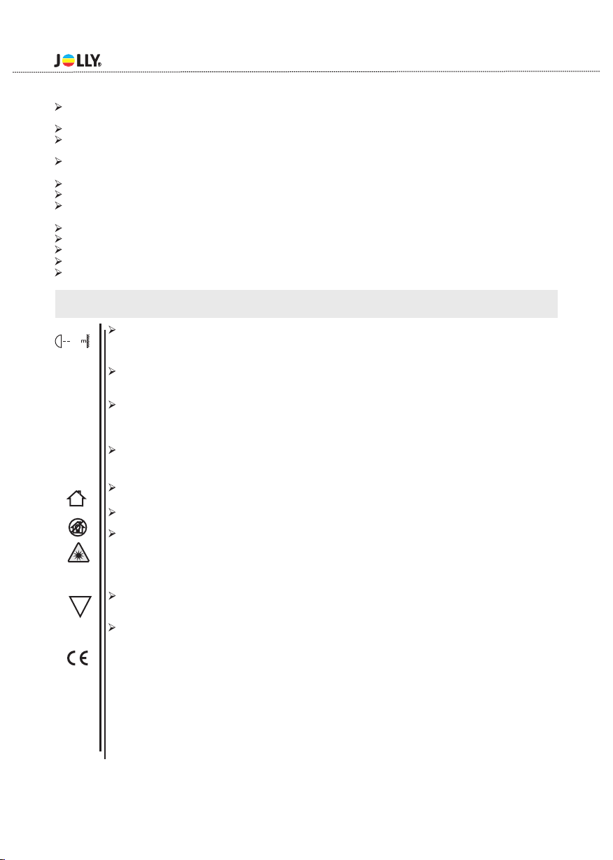
The minimum distance between light output and the illuminated surface must be more than 0.2 meters.
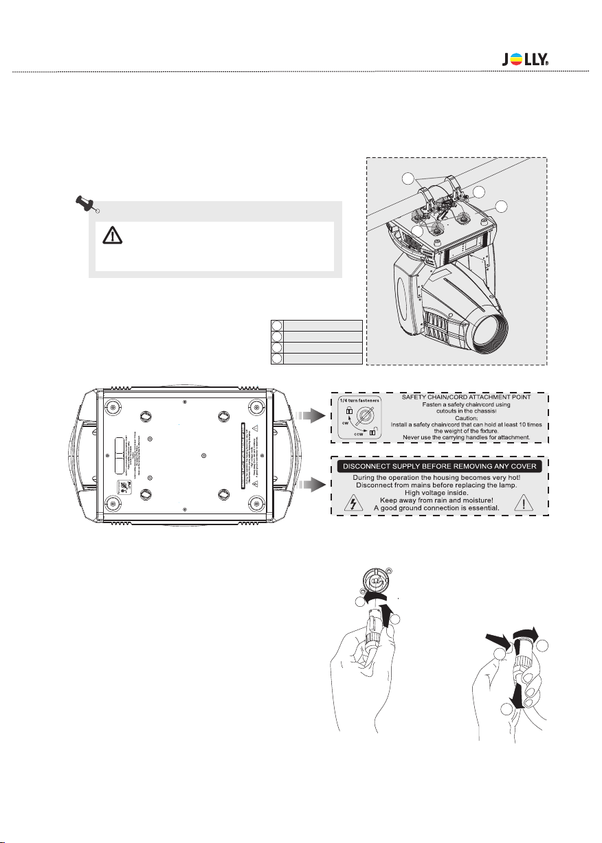
Make sure that the area below the installation place is blocked when rigging,derigging or servicing the fixture.
Always fix the fixture with an appropriate safety rope, Fix the safety rope at the correct holes only.
Operate the fixture after having checked that the housing is firmly closed and all screws are tightly fastend.
The lamp must never be ignited if the objective-lens or any housing-cover is open, as discharge lamps may ex-
plose and emit a hign ultraviolet radiat, which may cause burns.
The maximum ambient temperature 40°C must never be exceeded.
Operate the device only after having familiarized with its functions. Do not permit operation by persons not qua-
lified for operating the device. Most damages are the result of unprofessional operation!
Please use the original packaging if the device is to be transported.
Please consider that unauthorized modifications on the device are forbidden due to safety reasonsl.
3.Operating determinations
E
!
- 3 -
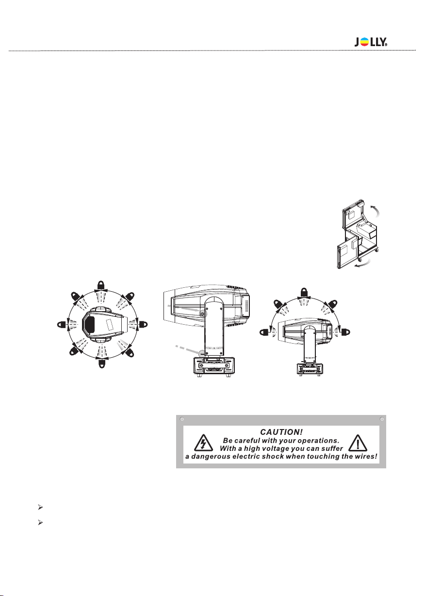
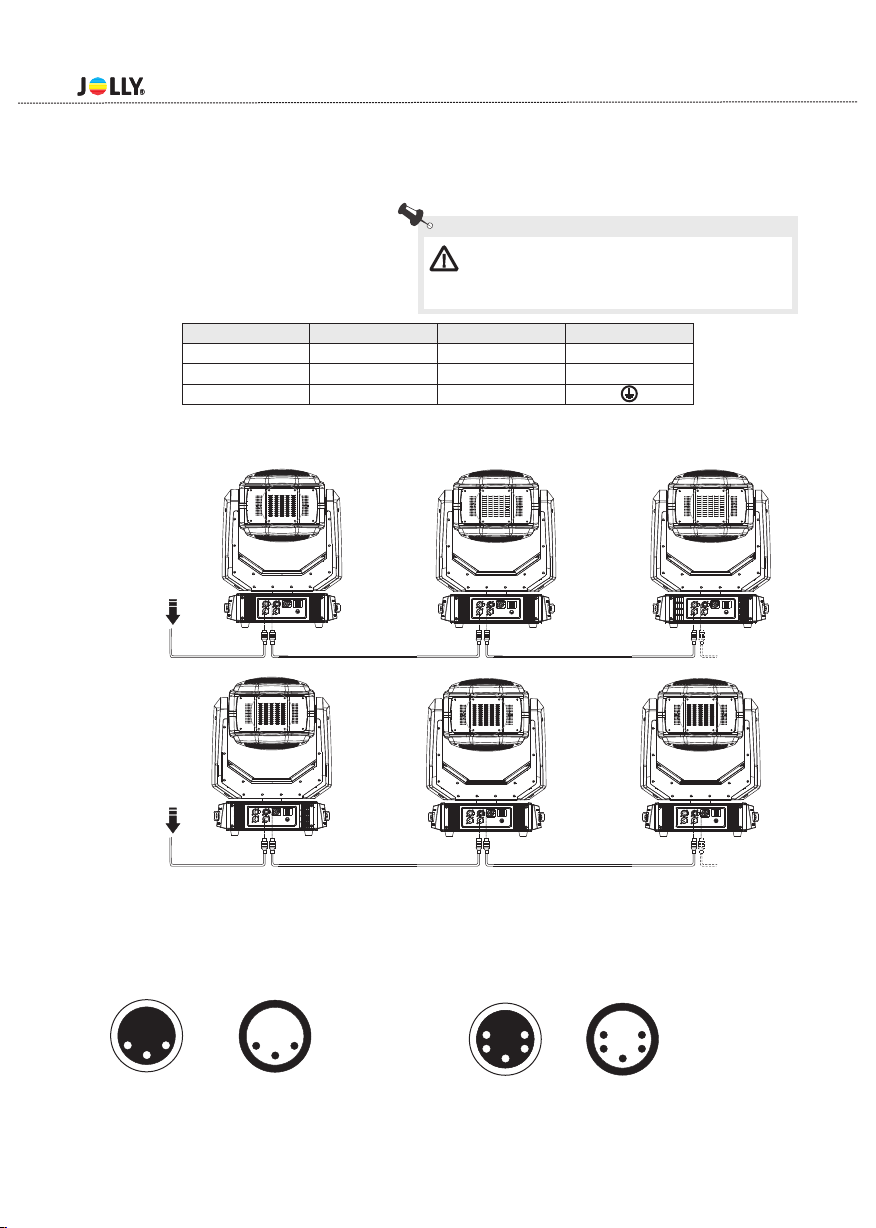
Protection against electrical shock
Connection must be made to a power supply system fitted with efficient earthing (Class I appliance ac-
cording to standard EN 60598-1) .It is, moreover, recommended to protect the supply lines of the proj-
ectors from indirect contact and/orshorting to earth by using appropriately sized residual current devi-
ces.

4.1 Mounting
For the various mounting positions of the FIXTURE(standing on the floor, sideways or hanging different
accessories kits are available.
Through this a safe and firm installation is assured.
You’ll find special connectors on the bottom side of the system which are put to use here.
4.2 Installing the Clamps
Please consider the respective national norm s during the Installation!The installation must only be car-
ried out by an authorized dealer!
The installation of the projector has to be built and constructed in a way that it can hold 10 times the wei-
ght for 1 hour without any harming deformation.
The installation must always be secured with a secondary safety attachment, e.g.an appropriate catch
net.This secondary safety attachment must be constructed in a way that no part of the installation can
fall if the main attachment fails.
When servicing the fixture staying in the area below the installation place,on bridges,under high working
places and other endangered areas is forbidden.
The operator has to make sure that safety-relating and machine-technical installations are approved by
an expert before taking into operation for the first time and after changes before taking into operation an-
other time.
The operator has to make sure that safety-relating and machine-technical installations are approved by
an expert after every four year in the course of an acceptance test.
The operator has to make sure that safety-relating and machine-technical installations are approved by
a skilled person once a year.
The projector should be installed outside areas where persons m ay walk by or be seated.
Important!Overhead rigging requires extensive expering CE,including (but not limited to)calculating
working load limits, installation material being used, and periodic safety inspection of all installation ma-
terial and the projector. If you lack these qualifications, do not attempt the installation yourself, but inste-
ad use a professional structural rigger. Improper installation can result in bodilyinjury and or damage to
property.
The projector has to be installed out of the reach of people.
If the projector shall be lowered from the ceiling or high joists, professional trussing system s have
to be used. The projector must never be fixed swinging freely in the room .
Caution Projectors may cause severe injuries when crashing down! If you have doubts concerning the
safety of a possible installation, do not install the projector!
Before rigging make sure that the installation area can hold a minim um point load of 10 times the
projector s weight.
4.Rigging the fixture
- 4 -
Pay attention to the regulations of CE.
Installation by qualified staff to complete.
If this device will be operated in any way different to the one described in this manual, the product may suffer
damages and the guarantee becomes void.Furthermore, any other operation may lead to dangers like short-circ-
uit,burns, electric shict,burns due to ultraviolet radiation,lamp explosion,crash etc.

The projector can be placed directly on the stage floor or rigged in any orientation on atruss without alte-
ring its operation characteristics.
For overhead use,always install a safety-rope that can hold at least 10 times the weight of the fixture.You
must only use safety-ropes with screw on carabines.Pull the safety-rope through the two apertures on the
bottom of the base and over the trussing system etc.
- 5 -
Warning: it is necessary to make sure that
the installation location is perfectly appropriate,
and the installation location is safe and reliable.
2
4
1
3
1
2
3
4mounting plate
secure chain
omega holder
Lock catch
4.3 Power supply connection and cut off
Connect the light source to the main power source with the plug of the power cord, or cut off the power
supply:
Connection: according to procedures, the power
plug and socket is inserted into the groove one one
alignment,rotation.
Cut off:according to procedures,press the button
on the rotating plug,pull out. 12
3
1
2

2 1
3
2 1
3
5 1
4 2
3
5 1
4 2
3
5 1
4 2
3
1:Ground
2:Signal(-)
3:Signal(+)
1:Ground
2:Signal(-)
3:Signal(+)
4:N.A.
5:N.A.
2 1
3
5 1
4 2
3
4.5 DMX-512 connection/connection between fixtures
Only use stereo shieded cable and 3-pin XLR-plugs and connectors in order to connect.
Caution
At the last fixture,the DMX-cable has to be terminated with a terminatou. solder a 120 resistor between
signal(-) and Signal (+) into a 3-pin XLR-plug and plug it in the DMX-output of the last fixture.
DMX iutput
3-pin XLR socket
DMX iutput
5-pin XLR socket
DMX output
3-pin XLR socket
DMX output
5-pin XLR socket
4.4 Power Connection
mains with the enclosed power cable and plug.
If you wish to change the power supply settings, see the chapter appendix Connect the fixture to the
L
N
CABLE(EU) CABLE(US) Pin
Brown Black Live
Yellow/Green Green Earth
Light blue White Neutral
INTERNATIONAL
- 6 -
Warning: please verify the power of the power
supply equipment prior to the connection! Earth wire
must be grounded!
DMX512 DMX512

5.Description of the device
DMX Terminator Diagram
-For installations where the DMX cable has to run a long distance or
is In an electrically noisy environment it is recommended to use a
DMX terminator. This help in preventing corruption of the signal by
electrical noise. The DMX terminato r is simply an XLR plug witha
120 resistor connected between pins 2 and pins3, which is then
plugged into a the output XLR socket of the last ifxture in the chain.
Ω
1
2
3
12 0Ω
PIN2 PIN3
- 7 -
Head
Tilt °,
1.
270 Fixture could auto
reset.
Arm
Pan °,
2.
540 Fixture could auto
reset.
3.Base
BACK PANEL
4.3-pin XLR female
5.5-pin XLR female
6.Power-in
7. Power switch
8.Main Fuse
9.5-pin XLR male
10.3-pin XLR male
CINTROL PANEL
11.Status indicator lamp
12.Touch screen
13.MODE button
14.UP button
15.DOWN button
16.ENTER button
17.WDMX Wire
17.WDMX wire
4 65 7
10 9 8
11 12 1314
16 15

6.Dimension
- 8 -
514mm
(20.24”)
551mm
(21.69”)
404mm
(15.90”)
247mm
(9.72”)
726mm
(28.58”)
417mm
(16.42”)
166mm
(6.54”)

7.Display control
7.1 Navigation in the Menu
7.2 Display Operation
Using the buttons or touch screen, and this can be simply and easily set the address code and
code.
functions
If you view or modify the lighting feature set, then press ENTER button, the display will enter the menu
interface. Both there is sub menu corresponding to the functional operation of the main menu. Each of the
menus is representative of the specific features of the lamp. The specific contents shows as the table
menu below.
Set or browse lighting function, press UP or DOWN button.
Press ENTER to save your changes or enter the submenu.Press the UP or DOWN can change the nume-
rical (increase or decrease in value).
Press the MODE button to return to menu. Set a time 1 to 10 minutes automatically exit menu interface
and close the screen.
Put through power supply, open the power switch of lamps and lanterns, display show the company
website. According to the main interface, as shown in figure:
In the main interface, press "MODE" button to view the software version, press the "UP" "DOWN" can m-
odify the DMX address.
If the screen " " icon is green,said DMX signal connection is normal, this state can be used to check th-
elamps and lanterns and connection between the control table is normal.
LOGO
This lamp can be set to turn off the automatic flip screen function, touch this " “ icon can be manually
flip screen.
menu interface
E12:BusErr1 01
E15:Ballast Error 07
E17:BD1 BUS Erro r 9 9
E18:BD2 BUS Erro r 9 9
E19:BD3 BUS Erro r 9 9
Mode EnterUp Down
001
1
001-021Settings
1
Main interface
A
001
1
001-023
Se tti ngs
1
Dmx Input
Wired Input
Wireless Input
Wireless In/
XLR out
Dmx Input
Mode EnterUp Down
Dmx Address
0 10
Mode EnterUp Down
Set Up
Inforamtion
Personality
Manual Control
Advanced
Mode EnterUp Down
Fixture ID
00 10
Channel Mode
Mode1 1-23
Mode2 1-18
Mode EnterUp DownMode EnterUp Down
Press this area for 2 seconds
to modif y the DMX address.
Main interface
Can view the company LOGO,web
site, hardware, software version, dat e.
CH-001: 000.0 % 000
CH-002:PAN Fine 0 00.0% 000
CH-003:Tilt 000.0% 000
CH-004:Tilt Fine 000.0% 000
CH-005:Color1 000.0% 000
CH-006:Rotation Gobo Select 00 0.0% 000
CH-007:Rot.gobo indexing and rotation 000.0% 000
CH-008:Static gobos 000.0% 000
CH-009:Static gobo 2 0 00.0% 000
CH-010:Static gobo 2 speed 0 00.0% 000
PAN
Mode EnterUp Down
- 9 -

*Click on the main menu of the icon and value to view set of the relevant lighting information. If there is
symbol of the " " on the display, it indicates that the device may be wrong , if the symbol was blue, the
contents are errors appeared, click to clear. When the symbol is yellow, you can click on the view and
according to the references information to modify, If there is any doubt, please consult the relevant
technical personnel. (-for details see attached table).
- 10 -
CODE #
ERRO INFO CHECK MEASURMENT NOTE
E001 SpiFlashError Check the welding of memory IC
E002 BD1Init Error
E003 BD2Init Error
E004 BD3Init Error
E005 BD4Init Error
E006 BusErr1 Check main cable ABAB(485) chip
E007 SPDError Check the welding of master IC
E008 BD1 BUS Error
E009 BD2 BUS Error
E010 BD3 BUS Error
E011 BD4 BUS Error
E012 Pan FB. Err
E014 Tilt FB. Err
E013 Pan Zero Err
E015 Tilt Zero Err
E016 Prism Err1
E017 Focus Err
E018 Zomm Err
E019 R.Gobo Err
E020 Gobo RTErr
E021 ColourW1 Err
E022 ColourW2 Err
E023 St.Gobo Err
E028 Effect Err
E024 BFan Error Check the fan of Bottom
E025 LED Fan1 Error
E026 LED Fan2 Error
E027 ArtNet Mdl Err Check the fan of ArtNet、communication signal
Check cable of sensor, distance and location of
,magnets and sensor
Check the fan of Head LED
Check the communication signal 485& 485 chip &
memory IC
Check the communication signal& welding of
communication chip
RESET
ERROR
Check the light coupling line, optical coupling
switch and a plate of the relative position
measurement

7.3 Unit Menu
- 11 -
Remark
Dmx Address 001-XXX
Mode1 1-23
Mode2 1-18
Fixture Id 0001~9999
Fixture Times XXXXX h XX m
Led Times XXXXh XXm
Reset Led Time
Error List
BOARD 1: XX.XX%
BOARD 2: XX.XX%
BOARD 3: XX.XX%
Fans Monitor
DMX Values
DMX Diagnosis
Pan Reverse ON/OFF Defaul:OFF
Tilt Reverse ON/OFF Defaul:OFF
Feedback ON/OFF Defaul:ON
Wired Input Defaul
Wireless Input
Wireless In/XLR out
English
简体中文
Brightness
Screen Time out 0-10m
Touch Screen ON/OFF Defaul:OFF
Auto Screen ON/OFF Defaul:ON
Auto
Defaul
High
Silence mode
Reset ALL
Reset Pan/Tilt
Reset Colour
Reset Gobo
Reset other
Channel
Calibration lnput Password xxxx
Factory Default ON/OFF
Touch Calibration
Screen
Advanced
Manual
Control
Reset
Fan Mode
Personality
Diagnosis
Language Defaul:English
Pan/Tilt
Dmx Input Optional
Information
Set up Channel Mode Default:Mode1
LED Times

8.DMX protocol
- 12 -
Mode 1 Mode 2 Fade Type Function Dmx Value
1 1 Pan Pan 0-540° 0-255
2 Pan Fime Pan Fime 0-255
3 2 Tilt Tilt 0-270° 0-255
4 Tilt Fime Tilt Fime 0-255
Open 0
Color 1 14
Color 2 30
Color 3 44
Color 4 58
Color 5 72
Color 6 86
Color 7 100
Color 8 114
Open 127
Color 1 128-135
Color 2 136-143
Color 3 144-151
Color 4 152-159
Color 5 160-167
Color 6 168-175
Color 7 176-183
Color 8 184-191
CW,Fast→Slow CW 192-217
Stop 218-219
CCW,Slow→Fast CCW 220-245
Random color Fast→Slow 246-255
Empty position 0-4
Gobo 1 5-7
Gobo 2 8-10
Gobo 3 11-13
Gobo 4 14-16
Gobo 5 17-19
Gobo 6 20-22
Gobo 7 23-25
Gobo 1 26-28
Gobo 2 29-31
Gobo 3 32-34
Gobo 4 35-37
Gobo 5 38-40
Gobo 6 41-43
Gobo 7 44-46
Gobo 1 47-70
Gobo 2 71-94
Gobo 3 95-118
Gobo 4 119-142
Gobo 5 143-166
Gobo 6 167-190
Gobo 7 191-214
Empty position 215-220
Forwards gobo wheel rotation from fast to slow 221-235
No rotation 236-240
Backwards gobo wheel rotation from slow to fast 241-255
Gobo indexing,0-360° 0-255
5
Rot. gobo
indexing and
rotation
35 Color 1
Whatever Position
Position
Rotation Gobo
Select
Rotation - set rotation on channel 7( Mode 1)、5(Mode 2)
Gobo Shakes at variable speed from slow to fast
Gobo Position - set rotation on channel 7( Mode 1)、5(Mode 2)
Gobo rotation - set position on channel 5( Mode 1)、7(Mode 2)
Gobo indexing - set position on channel 7( Mode 1)、5(Mode 2)
46
7

- 13 -
No rotation 0-2
Forwards gobo rotation from fast to slow 3-126
No rotation 127-129
Backwards gobo rotation from slow to fast 130-253
No rotation 254-255
Open 0-9
Gobo1 10-19
Gobo2 20-29
Gobo3 30-39
Gobo4 40-49
Gobo5 50-59
Gobo6 60-69
Gobo7 70-79
Gobo8 80-89
Unused Range 90-99
Gobo1 100-109
Gobo2 110-119
Gobo3 120-129
Gobo4 130-139
Gobo5 140-149
Gobo6 150-159
Gobo7 160-169
Gobo8 170-179
Open 180-189
CW FX wheel rotation, fast →slow 190-214
FX wheel stops at its current position 215-218
CCW FX wheel rotation, slow* →fast 219-243
FX wheel stops at its current position 244-255
Unused Range 0-127
Position 1 Smooth 128-137
Position 1 Organic 138-147
Position 1 Metronome 148-157
Position 1 Run forwards, fast rewind 158-167
Position 1 Run backwards, fast rewind 168-177
Unused Range 178-187
Position 2 Smooth 188-197
Position 2 Organic 198-207
Position 2 Metronome 208-217
Position 2 Run forwards, fast rewind 218-227
Position 2 Run backwards, fast rewind 228-237
Unused Range 238-255
Stop 0-10
Animation speed slow → fast 11-255
Prism out 0-9
Prism indexing 10-59
Prism rotation 60-109
Unused Range 110-255
Prism indexing 0-255
No rotation 0-2
Forwards Prism rotation from fast to slow 3-127
No rotation 128-129
Backwards Prism rotation from slow to fast 130-255
Open 0-9
Pattern 1 10-14
Pattern 2 15-19
Pattern
sellection
1113
7 5
Rot. gobo
indexing and
rotation
The channels are blocked: Pris,Colour whee, Static gobo, Rotating gobo .
set position on channel-22(Mode 1)、19(Mode 2)
Prism insertion
Prism rotation
Prism indexing - set position on channel,21(Mode 1)、18(Mode 2)
Prism rotation - set position on channel,21(Mode 1)、18(Mode 2)
9
12 10
9 7
8 6 Static gobos
Gobo Position
10 8 Static gobo 2
speed
Static gobo 2
Random gobo functions:set time on channel 10(Mode1)or 8(Mode2)
Gobo Shakes at variable speed from slow to fast
11
Mode 1 Mode 2 Fade Type Function Dmx Value

- 14 -
9.Maintance and cleaning
Pattern 3 20-24
Pattern 4 25-29
Pattern 5 30-34
Pattern 6 35-39
Pattern 7 40-44
Pattern 8 45-49
Pattern 9 50-54
Pattern 10 55-59
Pattern 11 60-64
Pattern 12 65-69
Pattern 13 70-74
Pattern 14 75-79
Pattern 15 80-84
Pattern 16 85-89
Raw DMX 90-255
14 12 Frost Focus moves linearly into the light beam 0-255
Iris linearly open from minimum to maximum aperture 0-131
Iris pulsation from slow to fast speed 132-171
Iris pulsation from slow to fast speed with fast opening 172-211
Iris pulsation from slow to fast speed with fast closing 212-251
Maximum aperture 252-255
16 14 Zoom Zoom linearly moves from narrow to wide beam 0-255
17 Zoom Fine Fine Zoom positioning 0-255
18 15 Focus Focus moves linearly from far to near position 0-255
19 Focus Fine Fine focus positioning 0-255
Close 0-3
STROBE SLOW→FAST 4-103
OPen 104-107
PULSATION SLOW→FAST 108-207
Open 208-212
Random Strobe SLOW→FAST 213-251
Open 252-255
21 17 Dimmer Dimmer 0-100% 0-255
22 Dimmer Fime Dimmer Fime 0-255
Unused Range 0-70
Disable zoom/focuslinking– 5 sec. 71-79
Enable zoom/focus linking,near distance(5meters) (default setting)-5 sec. 81-89
Enable zoom/focus linking,ediumdistance(8meters) – 5 sec. 91-99
Enable zoom/focus linking, far distance(12meters) – 5 sec. 100-109
Reset Complete 110-119
Reset Pan/Tilt 120-129
Reset Color 130-139
Reset Gobo 140-149
Reset Other-Iris,Prism,Frost,Zoom,Focus. 150-159
Dimmer Curve 1 =linear 160-169
Dimmer Curve 2 =Gamma1.5 170-179
Dimmer Curve 3 =Gamma2.0 180-189
Dimmer Curve 4 =S 190-199
Fans mode: High 200-209
Fans mode: Auto 210-219
Fans mode: Silence 220-229
Unused Range 230-255
Pattern
sellection
To activate following functions , stop in DMX value for at least 5 sec.
Stopper/Strobe
Function
16
23 18
15 13
20
13 11
Iris
Mode 1 Mode 2 Fade Type Function Dmx Value
DANGER:Disconnect from the mains before starting any maintenance work.

10.1 Electrical paramters
10.Electric equipment specification
SOURCE:
POWER:
VOLTAGE:
400W White LED
500W
AC100-240V 50/60HZ
Color temperature:8000K
Life time for LEDs over 20000 hours
10.2 Weight and dimensions
Dimensions:514X4 X551
NET WEIGHT:28Kg
Dimensions(Carton package):521X506X816mm
17 mm
10.3 Channel Characteristics
2.Scan: Pan540°,Tilt270°,Scan speed adjustable.Fixture could auto reset.
3.Colour wheel: one open+8colors.half-color effects.
4.Gobo wh eel:one open+7 gobos. Fix gobo wheel :one open+8gobos.
5. Prism system:1 rotating of faces.
1.Channel:23、18 DMX -512.
- 15 -
LED
Turn off the LED first to better protect the device when the fixture is turned off. Turn off the power after
running for at least 5 minutes
Don't touch the bulb with your hands.Once contacting with your hands,scrub with alcohol and then dry
with linen.
When the light is on, the bulb runs at high pressure,so there is a risk of broken.It is related to the duration
of using,temperature and unreasonable operation.Therefore, please do not use lamp over the life span.
The using of LED should not exceed hours, otherwise it can damage device. Check the running
time of the fixure regularly.When the LED is used around 30000 hours, We strongly recommend that you
change the lamp.After replacing it,the used time of LED can be removed and reset.
Avoid operating in dirty and dusty environment, clean and maintain lamps regularly. Wipe the outside of
the lens at least every 20 days. Wipe the internal fan at least every 30 days
It is absolutely essential that the fixture is kept clean and that dust,dirt and smoke fluid residues must not
buildup on or within the fixture. Otherwise, the fixtures light-output will be significantly reduced. Regular
cleaning will not only ensure the maximum light-output, but will also allow the fixture to function reliably
through out its life. A soft lint-free cloth moistened with any good glass cleaning fluid is recommended,
under no circum stances should alcohol or solvents be used!
The front objective lens will require weekly cleaning as smoke-fluid tends to building up residues,reduc-
ing the light-output very quickly.The cooling-fans should be cleaned monthly.
The gobos may be cleaned with a soft brush,The interior of the fixture should be cleaned at least annua-
lly usinga vacuum-cleaner or an air-jet.
There are no serviceable parts inside the device except for the LED and the fuse.
Please disconnect the power supply before replacing the fuse and bulb. When replacing them, adopt the
same mode.
30000

- 16 -
6. Zoom:linear amplifier.
7. Focus:linear focus with auto function.
8.Demmer:electronic dimming,linear dimmer.
9. Strobe:electronic strobe,with strobe mode of synchronistical,pulse and random.
10.Iris:linear adjustment from minimum to maximum.
10.4 Menu Function
1. .
2.Each DMX Value displayable.
3.Time of automatic turning off is able to set on the display,when operating pan/tilt,Color and
gobos, strobe are turn off and able to set freely.
4. Display the time using of lighting feature and lamp as well as the times of turning on for lamp.
5. You can switch on and off the lamp via the control panel or via your DMX controller. It must be
noted that it has to be cold before re-stricking.
6.After the DMX signal is disconnected, the display will be bright and dark.
7.Software upgrade function.
Touch screen,English/Chinese menu
10.5 light table
Projection distance(m)
10 20
15 25
Φ1.04
Φ6.4
Φ1.56
Φ9.6
Φ2.08
Φ12.8
Φ2.6
Φ16
Φ0.52
Φ3.20
1630 410 102
185
39800 9950 24904420
5
65
1590
36°
36°Illuminance(Lux)
6°Illuminance(Lux)
6°
Flare diameter(m)
The minimum Angle 6°Flare diameter(m)
Maximum Angle36°Flare diameter(m)
Table of contents
Other Jolly Dj Equipment manuals

Jolly
Jolly D5-BS User manual

Jolly
Jolly LT-1516 User manual

Jolly
Jolly X-1000 Spot User manual

Jolly
Jolly LP-1512 Zoom User manual

Jolly
Jolly A-7 SPOT User manual

Jolly
Jolly X-1400 Wash PF User manual

Jolly
Jolly LP-H400 User manual

Jolly
Jolly X-Beam 440 User manual

Jolly
Jolly LL-300 Z User manual

Jolly
Jolly A-14 Coupe User manual
Popular Dj Equipment manuals by other brands

thomann
thomann Stairville DCL Flat Par 18x4W CW/WW user manual

Lightmaxx
Lightmaxx Slim Spot ARC user manual

ALPHA LITE
ALPHA LITE ALPHA 2000 User manual book

Rane
Rane SIXTY-EIGHT Operator's manual

Soundoff Signal
Soundoff Signal UltraLITE EL3H12A20 Series Assembly instructions

Infinity
Infinity TS-260C7 Profile Engine V2 manual