Always fix the fixture with an appropriate safety rope, Fix the safety rope at the correct holes only.
Operate the fixture after having checked that the housing is firmly closed and all screws are tightly fastend.
The lamp must never be ignited if the objective-lens or any housing-cover is open, as discharge lamps may ex-
plose and emit a hign ultraviolet radiat, which may cause burns.
The maximum ambient temperature 40°C must never be exceeded.
Operate the device only after having familiarized with its functions. Do not permit operation by persons not qua-
lified for operating the device. Most damages are the result of unprofessional operation!
Please use the original packaging if the device is to be transported.
Please consider that unauthorized modifications on the device are forbidden due to safety reasonsl.
If this device will be operated in any way different to the one described in this manual, the product may suffer
damages and the guarantee becomes void.Furthermore, any other operation may lead to dangers like short-circ-
uit,burns, electric shict,burns due to ultraviolet radiation,lamp explosion,crash etc.
- 3 -
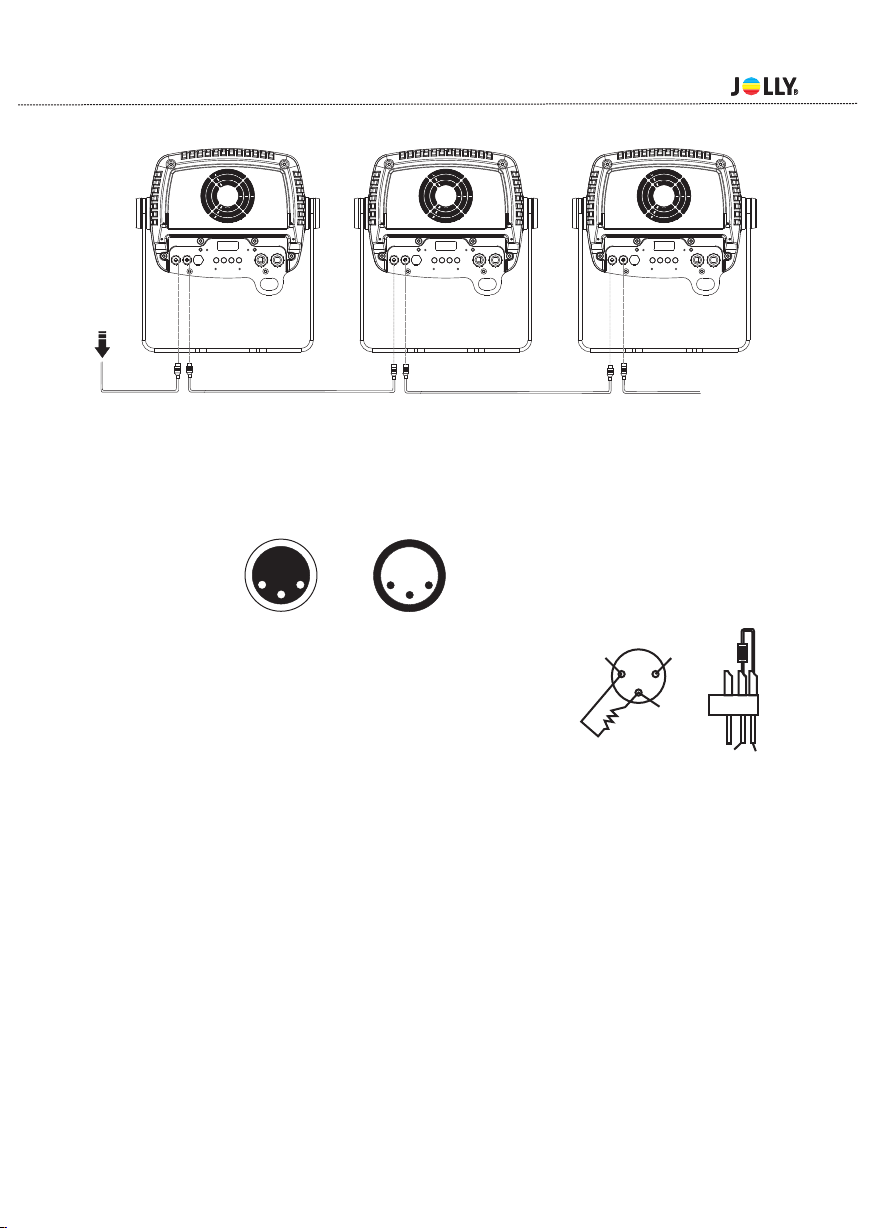
4.1 Mounting
For the various mounting positions of the FIXTURE(standing on the floor, sideways or hanging different
accessories kits are available.
Through this a safe and firm installation is assured.
You’ll find special connectors on the bottom side of the system which are put to use here.
4.2 Installing the Clamps
Please consider the respective national norm s during the Installation!The installation must only be car-
ried out by an authorized dealer!
The installation of the projector has to be built and constructed in a way that it can hold 10 times the wei-
ght for 1 hour without any harming deformation.
The installation must always be secured with a secondary safety attachment, e.g.an appropriate catch
net.This secondary safety attachment must be constructed in a way that no part of the installation can
fall if the main attachment fails.
When servicing the fixture staying in the area below the installation place,on bridges,under high working
places and other endangered areas is forbidden.
4.Rigging the fixture
Pay attention to the regulations of CE.
Installation by qualified staff to complete.
The operator has to make sure that safety-relating and machine-technical installations are approved by
an expert before taking into operation for the first time and after changes before taking into operation an-
other time.
The operator has to make sure that safety-relating and machine-technical installations are approved by
an expert after every four year in the course of an acceptance test.
The operator has to make sure that safety-relating and machine-technical installations are approved by
a skilled person once a year.
The minimum distance between light output and the illuminated surface must be more than 0.2 meters.
Make sure that the area below the installation place is blocked when rigging,derigging or servicing the fixture.