Joovv Mobile Stand User manual

Mobile Stand System
Assembly Guide

2
Warnings and Safety
Please review the following safety information prior to assembling your Joovv Mobile Stand. Attempting to assemble and use this equipment without
fully understanding its features and functions may result in unsafe operating conditions. Some Warnings and Cautions are also inserted within the manual
where they are most meaningful. Notes are also located throughout the manual to provide additional information related to specific features. If you have
a question regarding the installation, set up, operation, or maintenance, please contact Joovv Inc. at help@joovv.com.
WARNINGS identify conditions or practices that could result in serious adverse reactions or potential safety hazards.
CAUTIONS identify conditions or practices that could result in damage to the device or other equipment.
Warnings
• No modification of this system is allowed.
• System is only meant to support applicable Joovv products.
Cautions
• Read user manual prior to use and keep for future reference.
• Choking hazard, small parts. Keep away from small children.
• For interior use only, storage or installation of the system in direct sunlight may cause the system to yellow
or break down over time. Normal storage or installation in window-lit rooms is acceptable.
• Do not leave the system in any place that could be damaged by children, pets, pests, or liquids.
If you suspect your system of devices is damaged, contact customer service at help@Joovv.com.
• Do not install system near heated surfaces such as nearby fireplaces or ceramic heaters.
• Do not install or store system in humid or wet locations such as a sauna or wet sauna.
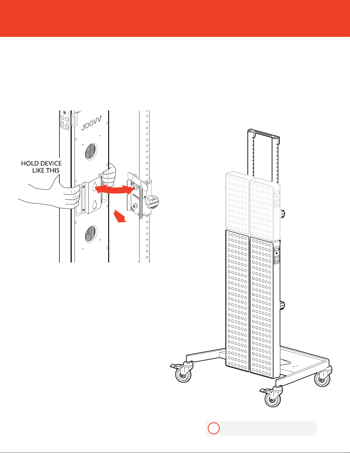
• Remove the device before adjusting height of Slider Pole Mount.
• When loosening the adjustment knob, do not exceed more than 1.5 turns counterclockwise to loosen.
Additional turns can cause the Slider Pole Mount to fall.
• Do not use power tools to assembly parts in this kit.
• Do not mount more than 2 devices per pole upright.
• Do not exceed mobile stand working load capacity of 38 kg.
• Do not push the device above 91 cm when on casters.
• Do not park mobile stand on an incline.
• Before use make sure to lock wheel casters.
Safety Standards
IIEC 60601-1: 2012 ed 3.1, IEC 60601-1-11:2015, IEC 60101-2-83:2019, IEC 60601-2-57:2011 (Audits to: IEC 60601-1-6, ISO 14971)
Conforms To: UL STD 60601-1, IEC STD 60601-1
Certified To: CSA STD C22.2 #60601-1

3
Table of Contents
Notices..........................................................................................................................................................2
Parts List .......................................................................................................................................................4
Install Wheel Casters and Adjust Leveling Nuts...........................................................................5
2 Pole Setup ...............................................................................................................................................6
3 Pole Setup .............................................................................................................................................. 12
Adding Spacers to Mounted Devices.............................................................................................. 18
Revision History....................................................................................................................................... 19
Warranty..................................................................................................................................................... 19
Return Policy............................................................................................................................................. 19
Contact Information.............................................................................................................................. 19

4
Insert
this end
Insert
this end
Parts List
N
O
L
M
G
B
F
E
K
H
D
A
A
B
C
D
E
F
G
H
I
J
K
P
L
Q
M
R
N
S
O
I
J
Pole Upright
Mobile Base
Wheel Caster x4
Slider Mount
Boot Bracket
Boot Washer
Top Bracket 2 Pole
Bottom Bracket 2 Pole
Top Bracket 3 Pole
Bottom Bracket 3 Pole
M6 Screw
M10 Screw
M10 Screw (boot bracket)
M4 Allen Key
M6 Allen Key
Vertical Alignment Plug
4 Plug
Horizontal Alignment Plug
O-Ring for Mini
C
Spacer Kit
P
Q
R
S
Included with Half Max
- Elite Setup Kits
i

5
Install Wheel Casters and Adjust Leveling Nuts
Install each Wheel Caster onto the Mobile Base. To level Mobile Base, adjust
leveling nuts where needed.
AM INCLUDING THIS ADDITIONAL VIEW INDICATING
NUT ADJUSTMENT DIFFERENT THAN FIRST.
IF NEEDED.
AM INCLUDING THIS ADDITIONAL VIEW INDICATING
NUT ADJUSTMENT DIFFERENT THAN FIRST.
IF NEEDED.
LEVELING
NUT

6
2 Pole Setup
Max Quad

7
Step 1 Step 2
Secure Boot Bracket to each Pole
Upright. To do so, attach the bracket
on the side of the pole that is marked
with the J label. Use Screw M to
attach each Boot Bracket as shown.
Connect each Pole Upright to the
Mobile Base. To do so, place the Boot
Bracket Washer on the Mobile Base
and connect using screws K and L as
shown.
K
L
M

8
Step 3 Step 4
Install Slider Mounts to Pole Uprights
and adjust to the desired heights.
Install top and bottom brackets using
screws K and L.
K
L
FOR QUAD AND ELITE
CONFIGURATIONS,
SLIDE THE MOUNT
ONTO THE (7) HOLE
(4) HOLES SHOWING
ABOVE THE MOUNT
4 HOLES
7 HOLES
11 HOLES
14 HOLES
FOR MAX
CONFIGURATIONS,
SLIDE THE MOUNT
ONTO THE (19) HOLE
(16) HOLES SHOWING
ABOVE THE MOUNT
16 HOLES
19 HOLES
11 HOLES
14 HOLES
FOR QUAD CONFIGURATION,
SLIDE THE TOP MOUNTS ONTO
THE POLE UPRIGHT SO (4) HOLES
ARE SHOWING ABOVE THE
MOUNTS
SLIDE THE BOTTOM MOUNTS
ONTO THE POLE UPRIGHT SO
(11) HOLES ARE SHOWING BELOW
THE MOUNTS
FOR MAX CONFIGURATION, SLIDE
THE TOP MOUNTS ONTO THE
POLE UPRIGHT SO (16) HOLES ARE
SHOWING ABOVE THE MOUNTS
SLIDE THE BOTTOM MOUNTS
ONTO THE POLE UPRIGHT SO
(11) HOLES ARE SHOWING BELOW
THE MOUNTS
G
H

9
Step 5
To adjust the Slider Mount, turn the knob counterclockwise ~1
turn and pull out. Slide the mount up or down based on your
desired height. To secure the Slider Mount tighten the knob by
turning it clockwise until hand tight.
1
4
1X
1X
TURN TO
LOOSEN
TURN TO
TIGHTEN
3
SLIDE UP
OR DOWN
FOR
DESIRED
HEIGHT
2
PULL OUT
WARNING!
When loosening the adjustment knob, do not exceed
more than 1.5 turns counterclockwise to loosen.
Additional turns can cause the Slider Pole Mount to fall.

10
Step 6
While holding the device as shown below, align the device over the Slider Mount
keyholes and slide the device down onto the Slider Mount to secure.
When mounting devices, mount bottom
devices first.
i
2
1
MOUNT
BOTTOM
FIRST

11
To remove the Solo or Mini Device from the Slider Mount,
follow the steps illustrated below.
PULL DEVICE
AWAY FROM
MOUNT
LIFT
DEVICE
WHILE
PUSHING
SAFETY HANDLE
PUSH HANDLE
1
3
2
TO MOVE LOCATION OF A SOLO OR MINI UNIT ON THE DOOR MOUNT:
STEP 1
STEP 2
STEP 3
PUSH HANDLE
PUSHING SAFETY HANDLE
LIFT DEVICE WHILE
PULL DEVICE AWAY FROM MOUNT
HOLD DEVICE
LIKE THIS
Step 7

12
3 Pole Setup
Step 1
Secure Boot Bracket to each Pole
Upright. To do so, attach the bracket on
the side of the pole that is marked with
the J label. Use Screw M to attach each
Boot Bracket as shown.
Step 2
Connect each Pole Upright to the Mobile
Base. To do so, place the Boot Bracket
Washer on the Mobile Base and connect
using screws K and L as shown.
K
L
M

13
Step 3
Install Slider Mounts to Pole Uprights and adjust to the desired height.
1 2
FOR QUAD AND ELITE
CONFIGURATIONS,
SLIDE THE MOUNT
ONTO THE (7) HOLE
(4) HOLES SHOWING
ABOVE THE MOUNT
4 HOLES
7 HOLES
11 HOLES
14 HOLES
FOR ELITE CONFIGURATION, SLIDE
THE TOP MOUNTS ONTO THE
POLE UPRIGHTS SO (4) HOLES ARE
SHOWING ABOVE THE MOUNTS
SLIDE THE BOTTOM MOUNTS
ONTO THE POLE UPRIGHTS SO
(11) HOLES ARE SHOWING BELOW
THE MOUNTS

14
Step 4
Install top and bottom brackets using screws K and L.
K
L
I
J

15
Step 5
To adjust the Slider Mount, turn the knob counterclockwise ~1
turn and pull out. Slide the mount up or down based on your
desired height. To secure the Slider Mount tighten the knob by
turning it clockwise until hand tight.
1
4
1X
1X
TURN TO
LOOSEN
TURN TO
TIGHTEN
3
SLIDE UP
OR DOWN
FOR
DESIRED
HEIGHT
2
PULL OUT
WARNING!
When loosening the adjustment knob, do not exceed
more than 1.5 turns counterclockwise to loosen.
Additional turns can cause the Slider Pole Mount to fall.

16
Step 6
While holding the device as shown below, align the device over the Slider Mount
keyholes and slide the device down onto the Slider Mount to secure.
2
1
MOUNT
BOTTOM
FIRST
When mounting devices, mount bottom
devices first.
i

17
To remove the Solo or Mini Device from the Slider Mount,
follow the steps illustrated below.
PULL DEVICE
AWAY FROM
MOUNT
LIFT
DEVICE
WHILE
PUSHING
SAFETY HANDLE
PUSH HANDLE
1
3
2
TO MOVE LOCATION OF A SOLO OR MINI UNIT ON THE DOOR MOUNT:
STEP 1
STEP 2
STEP 3
PUSH HANDLE
PUSHING SAFETY HANDLE
LIFT DEVICE WHILE
PULL DEVICE AWAY FROM MOUNT
HOLD DEVICE
LIKE THIS
Step 7

18
Adding Spacers to Mounted Devices
Spacers help keep the separate devices
aligned and immobile. See illustration
below for Spacer insert locations.
P Q R
When using the spacer kit with the Joovv Mini, utilize the included O-Rings with your spacer kit before inserting.
iSlide the O-Ring onto
the spacer plug

19
Warranty
All Joovv mounting accessories are covered by a 2-year limited warranty. Please visit our website at
https://joovv.com/pages/warranty for details of the limited warranty. To register your product, visit
https://joovv.com/pages/warranty for instructions. Failure to register will not aect your limited
warranty rights.
Return Policy
All mounting accessories come with a 60-day return period. If you’re not satisfied with your purchase
within the first 60 days, please visit our website at https://joovv.com/pages/returns for additional
details.
Contact Information
Joovv, Inc.
940 Calle Amanecer, Suite D,
San Clemente, CA 92673, USA.
Email us: help@joovv.com
Website: www.joovv.com
Online Setup instructions: www.joovv.com/setup
Revision History
Date Revision # Description of Changes
November 2020 JV-MKT-DOC-2806 (Ver.0) Ver.0 Release to market

JV-MKT-DOC-2806 Ver.0
joovv.com
Other manuals for Mobile Stand
1
Table of contents
Other Joovv Personal Care Product manuals
Popular Personal Care Product manuals by other brands

Dr. Kern
Dr. Kern Tandome Assembly instructions and operation manual

Vigan Mammoth
Vigan Mammoth Lady Two user manual

KHN Solutions
KHN Solutions AlcoMate user guide

BERTSCHAT
BERTSCHAT HEATED BODY WARMER PRO - DUAL HEATING user manual

Philips
Philips VisaPure SC5275 user manual

Bitvae
Bitvae C2 instruction manual