JOVY Systems Jetronix-Eco User manual

Operating Manual
Jetronix-Eco
Version 1.01 ●1/4/2013
Last edited: 01 April 2013
This document is copyright © by Jovy Systems® Limited. All rights reserved.
No part of this publication may be reproduced, transmitted, transcribed, stored in a retrieval system, or translated into any language, in any form or by any means,
electronic, mechanical, photocopying, recording, or otherwise, without prior written permission from Jovy Systems® Limited.
All copyrights, confidential information, patents, design rights and all other intellectual property rights of whatsoever nature contained herein are and shall remain
the sole and exclusive property of Jovy Systems® Limited. The information furnished herein is believed to be accurate and reliable.
However, no responsibility is assumed by Jovy Systems® Limited for its use, or for any infringements of patents or other rights of third parties resulting from its
use.
The Jovy Systems® Limited name and Jovy Systems® Limited logo are trademarks or registered trademarks of Jovy Systems® Limited.
All other trademarks are the property of their respective owners
This User Guide provides detailed guide on how to use the Jetronix-Eco Software

[Jovy Systems Limited] Operating Manual
[Jetronix-Eco] [Version 1.01]
Jetronix-Eco Operating Manual
Page 2 of 22 ©Jovy Systems 2013. All rights reserved
Table of Contents
1Introduction..................................................................................................................4
1.1 PURPOSE .......................................................................................................................................4
1.2 JETRONIX-ECO FEATURES............................................................................................................... 4
1.3 JETRONIX-ECO FIELD OF APPLICATIONS........................................................................................... 5
2Jetronix-Eco Technical Data.......................................................................................6
2.1 PRODUCT TECHNICAL SPECIFICATION ..............................................................................................6
2.2 JETRONIX-ECO MAIN PARTS DESCRIPTION.......................................................................................7
2.3 OPERATING PRECAUTION...............................................................................................................12
2.4 SAFETY INSTRUCTIONS..................................................................................................................12
3Initial Setup................................................................................................................13
3.1 MACHINE PACKAGE CONTENTS.......................................................................................................13
3.2 MACHINE INITIAL SETUP ................................................................................................................ 13
4Operating instructions...............................................................................................14
4.1 GETTING STARTED ........................................................................................................................ 14
4.2 PROCESS PROFILE PARAMETERS...................................................................................................16
5Warranty Policy .........................................................................................................20
6Getting the Technical Support..................................................................................21
7The Glossary .............................................................................................................22

[Jovy Systems Limited] Operating Manual
[Jetronix-Eco] [Version 1.01]
Jetronix-Eco Operating Manual
Page 3 of 22 ©Jovy Systems 2013. All rights reserved
About this Guide
This document is divided into the following chapters:
•Chapter 1, “Introducing Jetronix-Eco Product Information”.
•Chapter 2, “Jetronix-Eco Technical Data”
•Chapter 3, “Jetronix-Eco Initial Set up”
•Chapter 4, “Operating Instruction”
•Chapter 5, “Warranty Policy”
•Chapter 6, “Getting Technical Support”
•The glossary provides definitions of technical terms that
appear in the guide.
“Jetronix-Eco” Operating Manual organized in chapters and ends with a glossary of the
terms and abbreviations used.
Chapters contain all what's related to the Product features, Technical Data, Safety
precautions Product initial Set up, operating instructions and warranty policy ends how
to get the Technical support.
Table of content in the soft copy version is dynamic (cross reference); Right click over
any content then Ctrl + Right click will direct the reader to the content location.
For more detailed information regarding features, capabilities, and Technical
Information introduced with this release, contact our Live Technical Support through
SKYPE account jovysystemscs duty time is 10am to 5pm daily (China Local Time).
Alternatively, send email to support@jovy-sys.com or fill in a support form, from this link
http://www.jovy-systems.com/en/contacts/contact-us.html
For the most current version of this document, please visit: http://www.jovy-systems.com/

[Jovy Systems Limited] Operating Manual
[Jetronix-Eco] [Version 1.01]
Jetronix-Eco Operating Manual
Page 4 of 22 ©Jovy Systems 2013. All rights reserved
1 Introduction
1.1 Purpose
“Jetronix-Eco” Rework System is manufactured by Jovy Systems® Limited as the first product
in the Jovy Systems’ Economic Rework System lines. This operation manual provides the
detailed information about the product. Product feature shows what the product made for, as
well the field of application.
The Safety precaution is very important for user, product and work space safety. User should
follow and print it out if necessary
The Operating Manual provides a standard guide for the user. The user can develop own
operating method after complete understanding, following and practice the information in this
Manual.
The Operating Manual is the only reference for using Jetronix-Eco, it is recommended to read it
carefully before using the product.
1.2 Jetronix-Eco Features
Powerful machine: (max heating power: 3200 watt).
PID temperature control based microprocessor technology.
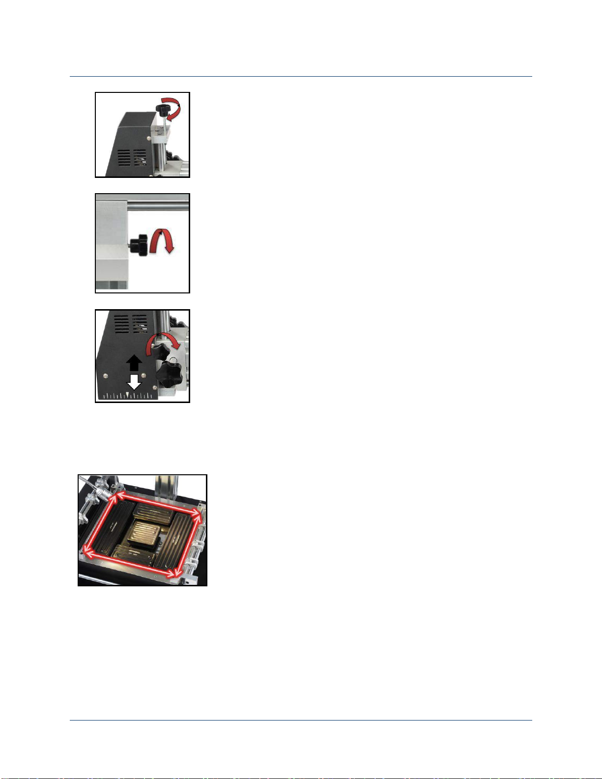
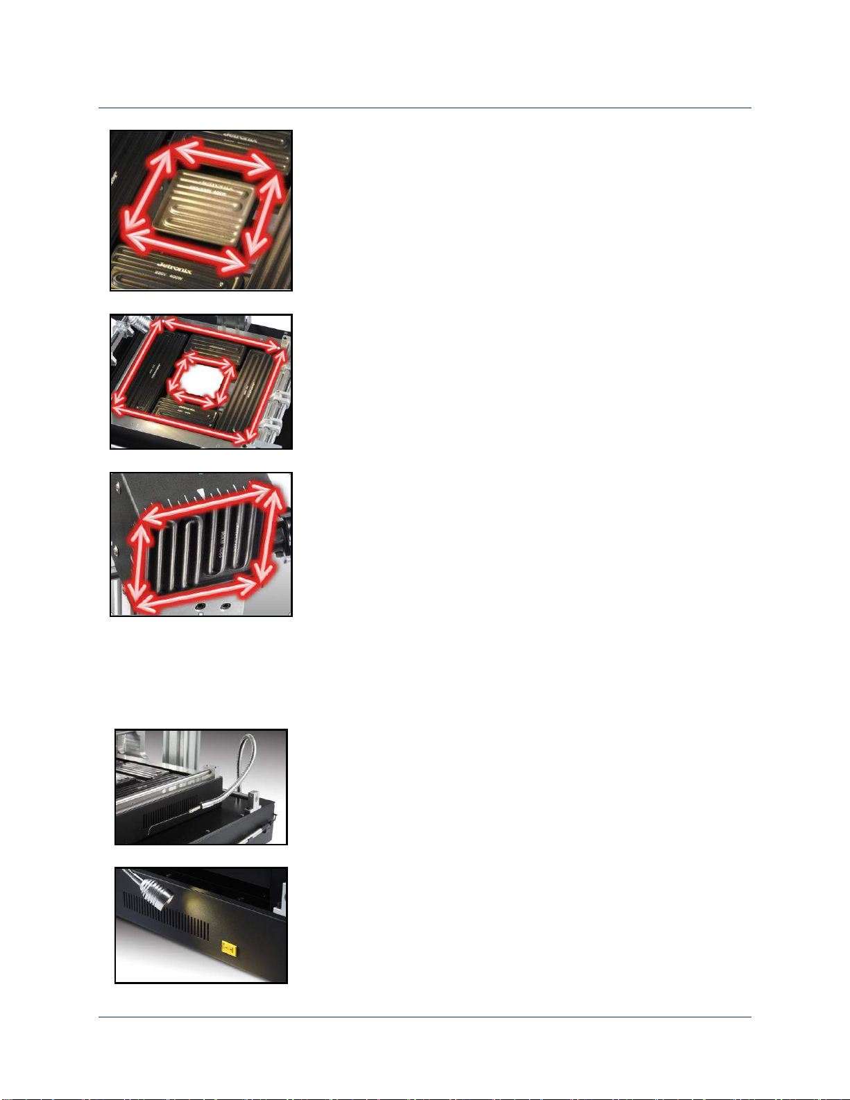
Three heating zones, Reflow zone, Inner preheating zone and Outer preheating zone.
Close loop heating environment.
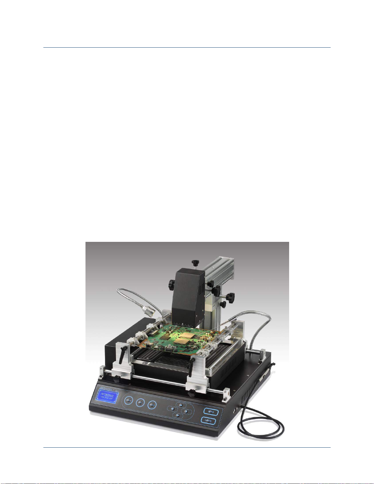
Upper heater can move Up/Down, In/Out and rotate 180°.
Two Channels thermocouple real time temperature reading (one optional).
Flexible thermocouple mounting embedded in a Flexi - tube.
Large preheating area up to (245mmX245mm).
Three stages for full process control.
Separate preheating stage for uniform preheats.
Built in 1 Watt LED light source.
Powerful pickup tool up to 120gm lifting power.
Graphical widescreen LCD.
Elegant user interface design.
Saving up to 50 profiles in machine memory.
User friendly software interface via USB 2.0
Economical Rework Station with high performance.
Convenient work space.
Safety alarm functions to protect PCB or application damage.

[Jovy Systems Limited] Operating Manual
[Jetronix-Eco] [Version 1.01]
Jetronix-Eco Operating Manual
Page 5 of 22 ©Jovy Systems 2013. All rights reserved
1.3 Jetronix-Eco Field of Applications
• BGA on Flex printed circuit.
• PTH connectors, card slots and sockets.
• Metal components housing.
• Micro lead frame.
• PBGA with heat sink.
• Processor plastic sockets.
• Metal Shielding.
• CSP and fine pitches BGA.
• Plastic PLCC.
• Through- hole sockets.
• Heavy Mass CCGA & CBGA.
• Under fill or epoxy coated components.
• QFN, VQFN and advanced design QFN.
• Package over package (POP)...
Graphical widescreen LCD.

[Jovy Systems Limited] Operating Manual
[Jetronix-Eco] [Version 1.01]
Jetronix-Eco Operating Manual
Page 6 of 22 ©Jovy Systems 2013. All rights reserved
2 Jetronix-Eco Technical Data
2.1 Product Technical Specification
Upper heater Power
& type
400 watt-Jetronix(special made)
Upper heater size
80*80 mm
Lower heater power
2800 watt-Jetronix(special made)
Lower heater size
245*245 mm
Total power
3200 watt
Control Method
PID controlling method
Light source
Built in flexible tube 1 Watt LED
Thermocouple type
K-type ,Built in Flex tube
LCD Type
128 *64 Pixel Graphical LCD
Power Supply
230 Volt AC,50/60 Hz.
USB connectivity
USB 2.0
Suction Pump
60 -90 dpi (Lifting power up to 150 gm.)
Cooling fan
Horizontal Cross flow Fan
Max. Application
size
290* 315 mm
Total weight
28 Kg.

[Jovy Systems Limited] Operating Manual
[Jetronix-Eco] [Version 1.01]
Jetronix-Eco Operating Manual
Page 7 of 22 ©Jovy Systems 2013. All rights reserved
2.2 Jetronix-Eco Main Parts Description
2.2.1 X/Y Movable PCB Holder
The X/Y movable PCB holder, the base equipped
with bearing to guarantee smooth movement.
The maximum PCB size is 219mm x 315mm
The PCB holder base fastener is known to stop
the movement after placing the PCB over the
holder.
PCB clamp, to tighten the PCB over the holder
and the fastener screw is to prevent the PCB
from moving or sag during the heating process
PCB clamp to be open before placing the PCB.
There are four movables along the clamp rail, for
fixing the PCB from its flat edges.
PCB clamp to be closed after placing the PCB.
The used clamps should not be closed over or
make minimal stress to any PCB comments.

[Jovy Systems Limited] Operating Manual
[Jetronix-Eco] [Version 1.01]
Jetronix-Eco Operating Manual
Page 8 of 22 ©Jovy Systems 2013. All rights reserved
2.2.2 Upper Heater Movement Description
Upper heater Arm move Forward and Backward.
The F/B Knob driver controls the movement
through gears and two roll bars.
Upper Heater Block moves Upward and
Downward. The U/D knob driver controls the
movement through gears and two roll bars.
Upper Heater Block with Arm together Rotate
180° from Left to Right and reverse. L/R rotation
fastener Stop the arm and make it non-movable.

[Jovy Systems Limited] Operating Manual
[Jetronix-Eco] [Version 1.01]
Jetronix-Eco Operating Manual
Page 9 of 22 ©Jovy Systems 2013. All rights reserved
Upper heater Block safety fastener
Upper heater Arm L/R rotation fastener
Upper heater Block fastener
2.2.3 Heaters Technical Details
Lower Heaters segmented in Two Zones. Total
Heaters Power is 2800 watts.

[Jovy Systems Limited] Operating Manual
[Jetronix-Eco] [Version 1.01]
Jetronix-Eco Operating Manual
Page 10 of 22 ©Jovy Systems 2013. All rights reserved
Lower Heater Zone 2 –Middle Heating Area,
Heater size is 80mm x 80mm with total power of
400 watts
Lower Heating Zone 3 –Sides Heating Area.
Two heaters of 60mm x 120mm with total power
of 800 watts (400 watts x 2) and Two heaters of
60mm x 240mm with total power of 1600 watts
(800 watts x 2).
Upper Heating Zone 1 –Upper heating Area.
One Heater of 80mm x 80mm with total power of
400 watts.
2.2.4 Machine peripherals
K-type thermocouple embedded inside Flexi tube
for easy placement over the PCB.
Optional K-type thermocouple channel.

[Jovy Systems Limited] Operating Manual
[Jetronix-Eco] [Version 1.01]
Jetronix-Eco Operating Manual
Page 11 of 22 ©Jovy Systems 2013. All rights reserved
LED light lamp embedded inside Flexi tube for
free easy placements.
Cross flow cooling fan directed above the lower
heaters level and under the PCB level to provide
cooling air carpet without direct effect to the PCB
or the Process.
Large PCB supports in two pieces to prevent
PCB damage during the heating process.
The suction Pen with high power of 60 dpi to 90
dpi (lifting objects up to 150gm weight)

[Jovy Systems Limited] Operating Manual
[Jetronix-Eco] [Version 1.01]
Jetronix-Eco Operating Manual
Page 12 of 22 ©Jovy Systems 2013. All rights reserved
2.3 Operating precaution
•Please carefully read the relevant information provided by the manual before starting using
this machine.
•Make sure that the power cord has been properly connected before using the machine.
•Install the rework station at a location free from splashing of water or other liquids.
•Install the rework station in a dry location.
•Install the rework station at a location free from excessive dust.
•Install the rework station at a location away from inflammable.
•Before starting any process, install the rework station at a location free from the direct airflow
impact from air Conditioner, heater or ventilator.
•Regularly clean the surface of the machine especially the guard glass.
•For more safety, please wear heat-proof gloves and never touch the high-temperature zone.
For further information or technical inquiries please write to support@jovy-sys.com
2.4 Safety instructions
Fire and explosion hazard
The upper heating element and the lower heating element become very hot during operation.
Flammable objects, liquids, and gases, must be removed from the work area of the device!
Do not use the system to heat any liquids, or containers under pressure.
Batteries and electrolyte capacitors can explode if heated excessively.
Attention burn hazard
Hot housing elements should not be brought into contact with the skin or materials that are
sensitive to heat. The housing parts of the IR system remain hot for several minutes after a
rework process.
Attention
The device contains voltage-conducting parts. There is a risk of fatal injury if inexperienced
personnel work on the unit.
Only experienced and qualified electriciansmay perform repair work.
•Choose the supply power voltage standard. (230V-250V/50Hz or 60Hz) before installing
•To avoid possible electric shock caused serious damage,please disconnect the power cord
from the outlet temporary before moving machines.
•Pull out the power if don’t use the machine for a long time.

[Jovy Systems Limited] Operating Manual
[Jetronix-Eco] [Version 1.01]
Jetronix-Eco Operating Manual
Page 13 of 22 ©Jovy Systems 2013. All rights reserved
3 Initial Setup
3.1 Machine package contents
The machine package includes the following items
- Basic unit
- 3 heaters, 1 heater from each type
- Operation Manual
- USB cable
- CD includes all needed operational files
3.2 Machine Initial Setup
-Take out the Basic Unit and put it on the horizontal worktable. Please note
that the machine weight is 30Kg.
-Remove any plastic or packing materials or any residues might burn when
switch the heaters first time.
-Please make sure that the supply voltage accords with the rated voltage on
the system nameplate then connect the power cord. 230V-250V/15A
-Insert the vacuum tube into the suction pump nozzle
-Run the CD and copy files into a known folder “Jetronix-Eco”

[Jovy Systems Limited] Operating Manual
[Jetronix-Eco] [Version 1.01]
Jetronix-Eco Operating Manual
Page 14 of 22 ©Jovy Systems 2013. All rights reserved
4 Operating instructions
4.1 Getting started
-Connect the machine to power source and switch on the machine, the
welcome screen will be displyed .
-When the LCD display Main Menu Screen choose
settings , scrolling Up/Down thourgh the UP and
Down press buttons to change the setting parameter press
Right to increase or Left to decrease the value or to toggle between
the available choices. Press Enter for Settings Menu . Press
to return to Menu or canel the input.
-Settings Menu include the following function parameters
oSafety set point, at this temperature value all
heaters will turn off and the cooling fan will turn on.
oAlarm set point, at this temperature value the
machine buzzer will start working, as audiable warnning.

[Jovy Systems Limited] Operating Manual
[Jetronix-Eco] [Version 1.01]
Jetronix-Eco Operating Manual
Page 15 of 22 ©Jovy Systems 2013. All rights reserved
oAuto Fan, ON to run the fan after process
Profile ends. OFF to run the fan
oTemperature Unit, to set temperature reading
display in °C or °F.
oKeypad Tone, On to activate audiable sound
with each press at any key pad button. OFF to deactivate the
audiable sound.
oTC1 is the default Main Thermocouple reading
–Built in machine thermocouple, to choose the optional
thermocouple as main TC, choose TC2 .

[Jovy Systems Limited] Operating Manual
[Jetronix-Eco] [Version 1.01]
Jetronix-Eco Operating Manual
Page 16 of 22 ©Jovy Systems 2013. All rights reserved
4.2 Process Profile Parameters
4.2.1 Create
Jetronix-Eco Process Profile divided into optional 1 to 4 stages, user can
create a process profile of at least 1 stage. Preheat stage is preprogramed
and heaters power predefined, while the other user define the hetars power
for each zone.
From Main Menu choose Profiler and press Enter
. Then, create a profile .
The first screen to Define the process profile stages, if the
preprogramed (preheat) stages needed, press ON. If the process profile
stages all to be defined by user, the Preheat stage should be
OFF
The required inputs for pre heat stage is the stage ends temperature and
dwell time needed at this temperature .

[Jovy Systems Limited] Operating Manual
[Jetronix-Eco] [Version 1.01]
Jetronix-Eco Operating Manual
Page 17 of 22 ©Jovy Systems 2013. All rights reserved
The rest of stages the process profile parameter include more inputs for
each heating zone power setting .
In the main tab use the Right and Left
buttons for stages parameter inputs or to review the stage prarameter.
To set a stage’s parameter press Up or Down button to the parameter
location change the input value (increase) by press Right button (decrease)
by press Left button.
In each stage parameters are as follow:
-Stage ends temperature value .
-Time in ends temperature (Dwell time) .
-Upper heater power Level from (0% to 100%) .
-Middle heater power Level from (0% to 100%) .
-Side heaters power Level from (0% to 100%) .
4.2.2 Save process profile
After input the process profile paramters save the profile in the machine
memory (Memory can save up to 50 profiles).
Press enter and choose Save profile .

[Jovy Systems Limited] Operating Manual
[Jetronix-Eco] [Version 1.01]
Jetronix-Eco Operating Manual
Page 18 of 22 ©Jovy Systems 2013. All rights reserved
The Process Profile will be numbered according to the available empty
profile number in the machine memory .
Write a Name for each Process Profile, choose from letters (A to Z) or
Numbers (0 to 9) , the Name is 5 digits length.
4.2.3 Run a Process Profile
Run a Process Profile just after create new one (the Process Profile could
not be saved after running) by chose Run instead of Save
or Run a Saved Process Profile saved in machine
Memory . The Process Profile parametters will be
displayed to ensure the settings before running the choosed profile.
The Running Process window display the temperature and stage
status ( the stage running will be in converted color).

[Jovy Systems Limited] Operating Manual
[Jetronix-Eco] [Version 1.01]
Jetronix-Eco Operating Manual
Page 19 of 22 ©Jovy Systems 2013. All rights reserved
The Thermocouple readings display the attached thermocouples (TC1,
TC2 or both).
The Process profile time displayed in seconds.
4.2.4 Delete a specific Process Profile
Delete specified one Process Profile from the machine memory by chose
Erase , then chose the profile number
and confirm Delete .
4.2.5 Erase all profiles in machine memory
Delete all Process Profiles saved in machine memory in one step by chose
Format , and confirm Delete all .
A message will be displayed that no profiles saved after this step
done .

[Jovy Systems Limited] Operating Manual
[Jetronix-Eco] [Version 1.01]
Jetronix-Eco Operating Manual
Page 20 of 22 ©Jovy Systems 2013. All rights reserved
5 Warranty Policy
Thank you for purchasing Jovy systems product, you did your good
decision. We committed with quality and warranty as follows:
The complete machine has a warranty period of 6 months from the time of
purchase.
The package include extra spare 3 heaters from each heaters type, easy to
install.
Warranty applied only from machines sold through our official distributors
or authorized resellers.
We provide online troubleshooting support and technical advice service
through the web site www.jovy-sys.com by support tickets. Alternatvliy,
refer to Getting the Technical Support.
Other manuals for Jetronix-Eco
1
Table of contents
Other JOVY Systems Soldering Gun manuals