jbc PHS-1B User manual

中文 31
Deutsch 21
Español 11
IR Preheater
Ref. PHS-B
English 2
Page
www.jbctools.com

Packing List
The following items should be included:
Heater Unit Console
Power Cord ................................................ 1 unit
Ref. 0009417 (100V/120V)
0009401 (230V)
Thermocouple .......................................... 1 unit
Ref. PH218
Kapton Tape .............................................. 1 unit
Ref. PH217
Manual ......................................................... 1 unit
Ref. 0017241
Ref. PHS-B
IR Preheater
IR Preheater ............................................................................................................................................... 1 unit
Ref. PHS-1B (120V)
PHS-2B (230V)
PHS-9B (100V)
2
www.jbctools.com

Features
Pedal socket (optional)
Ref. P-005
Heating Areas
Power socket
Power
Fixing brackets for
PHS-SA Convection
Preheater Support
Heater Unit
Console
Control Unit Start / Stop
Auxiliary Thermocouple (Type K) Input
Thermocouple
(Type K)
Ref. PH218
USB-B
connector to PC:
Update software
Zone A
Zone B
www.jbctools.com
3

Profiles by Temperature
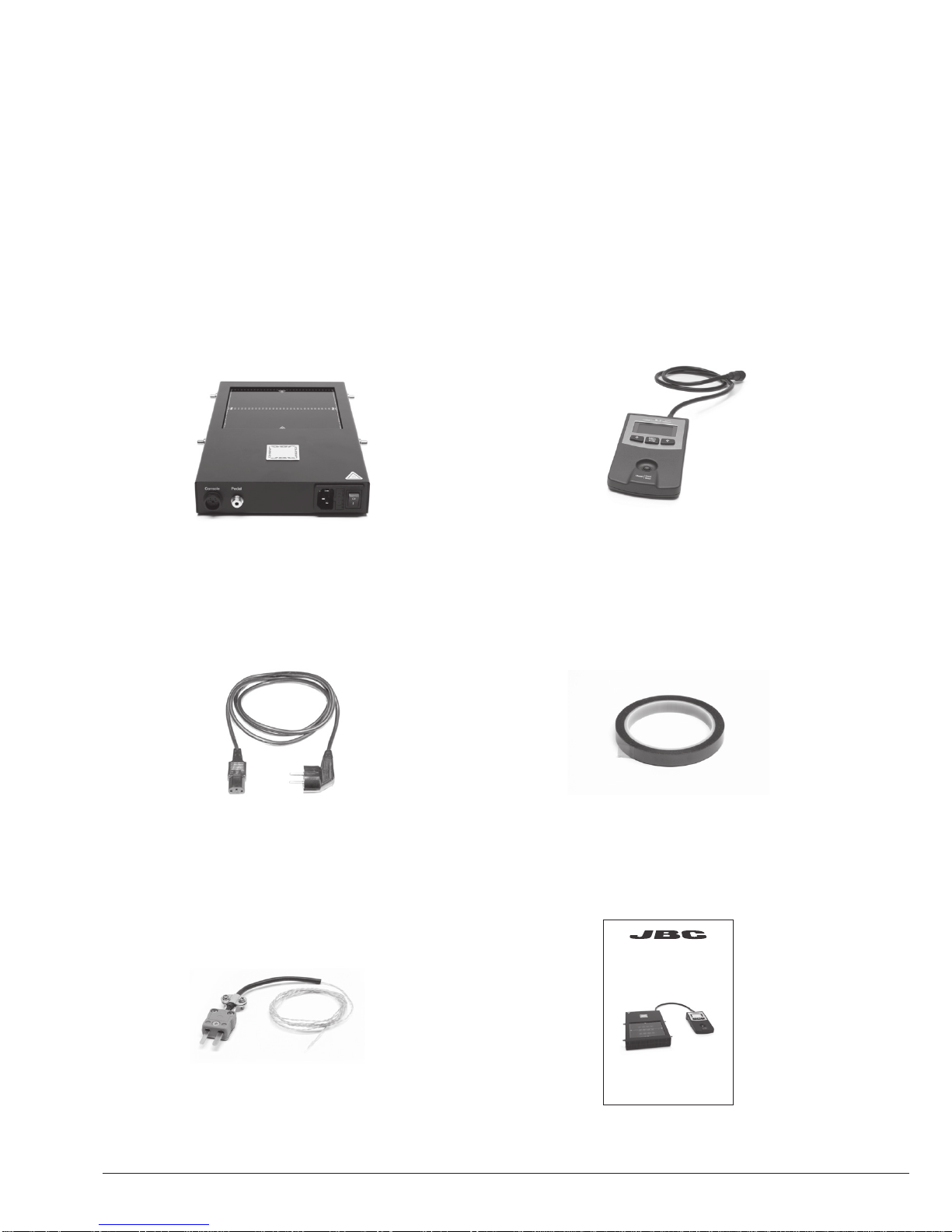
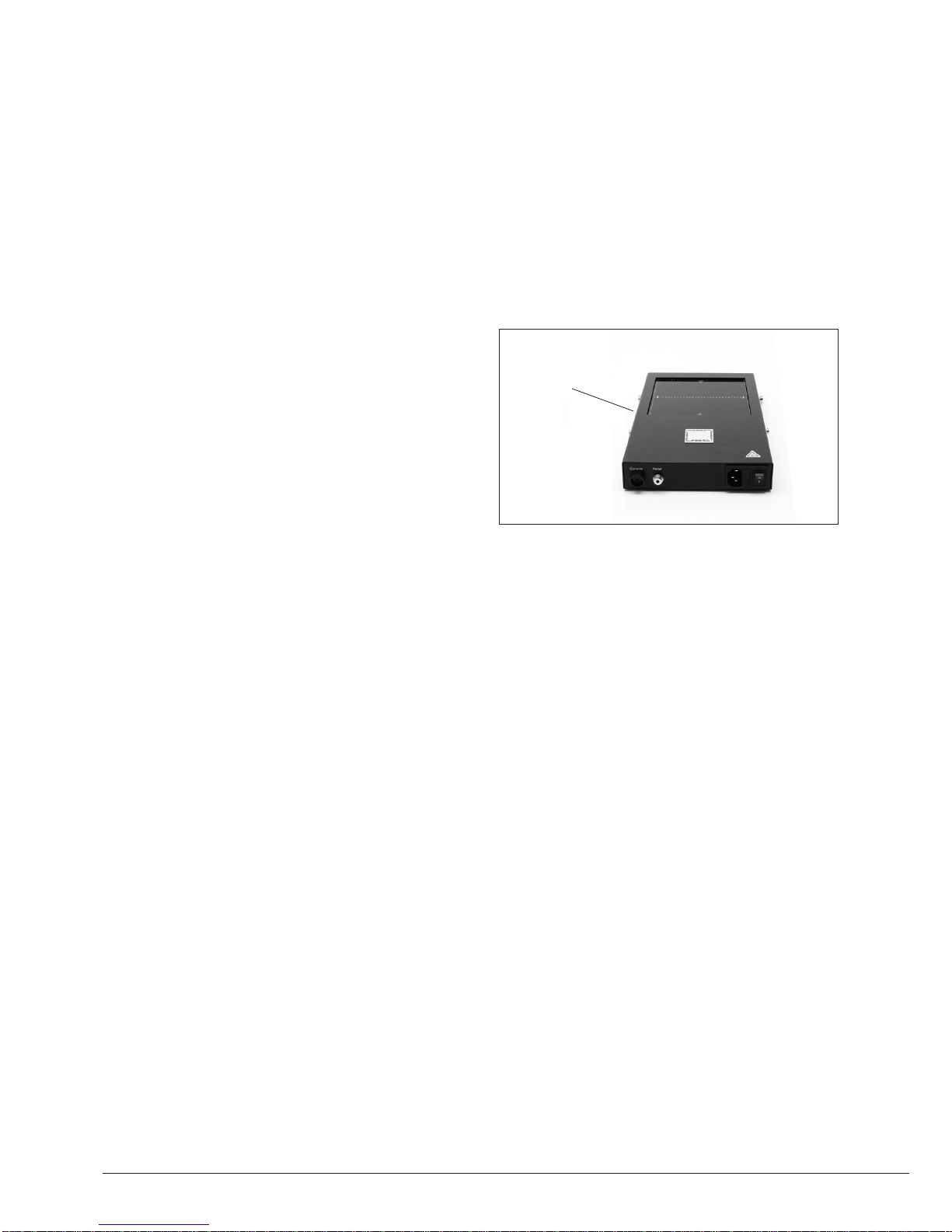
The usual way to run a profile is using the Thermocouple (TC) connected to the Control Input of the
console. JBC offers 3 predefined profiles (JBCset) and 10 profiles ready for you to personalize.
Why Infrared? The most efficient technology for PCB preheating
This is the most advanced, efficient and cost-effective method to preheat PCBs in any soldering job
or rework job. The low thermal mass of the infrared element gives outstanding control of the heat
output and the process temperature. This technology provides fast response, high heating rates and
uniform heating that ensure the best results.
Operation
JBCset profiles
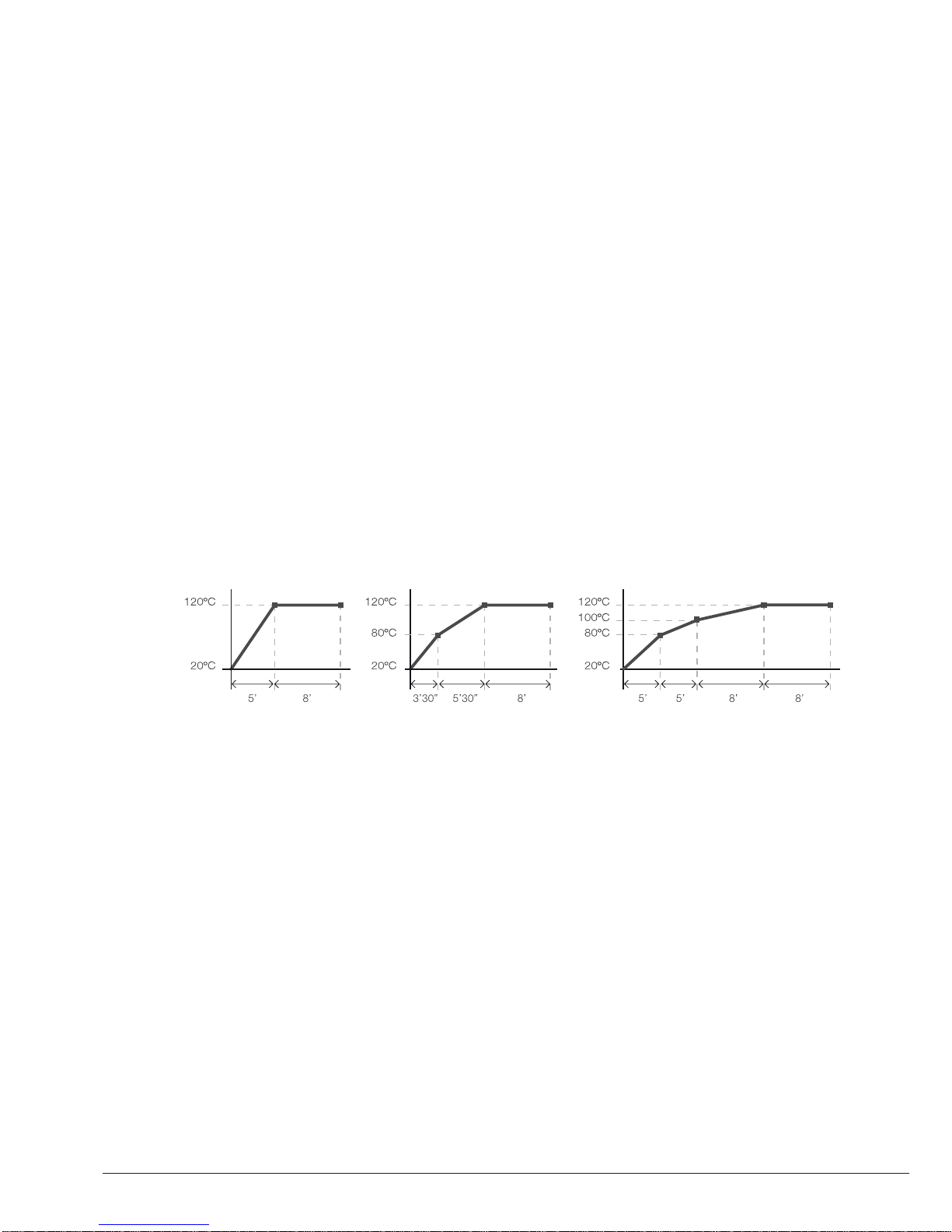
There are 3 profiles predefined by JBC: A, B and C. The difference between them is the number
of steps: 2, 3 or 4. The thicker your PCB is and the more layers it contains, the more steps are
needed to obtain a gradual warming.
These profiles are not modifiable but they can be used as a template to create your own profiles.
JBCset A
2 steps
JBCset B
3 steps
JBCset C
4 steps
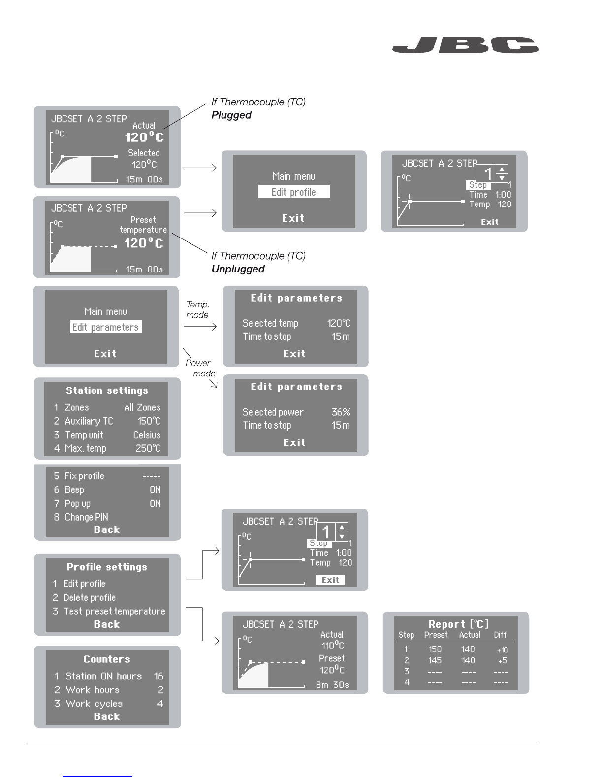
For repetitive jobs we recommend running profiles without the Thermocouple (TC). Once any
profile has been run to the end, the system has all the process data which you can save.
Once it is saved, you can run this profile without connecting the Thermocouple (TC). The heating
process will the same as long as the same working conditions are respected.
User profiles
You can create your own profiles from the JBCset profiles. On the work screen of the profile,
press the Enter button and choose the option Edit profile.
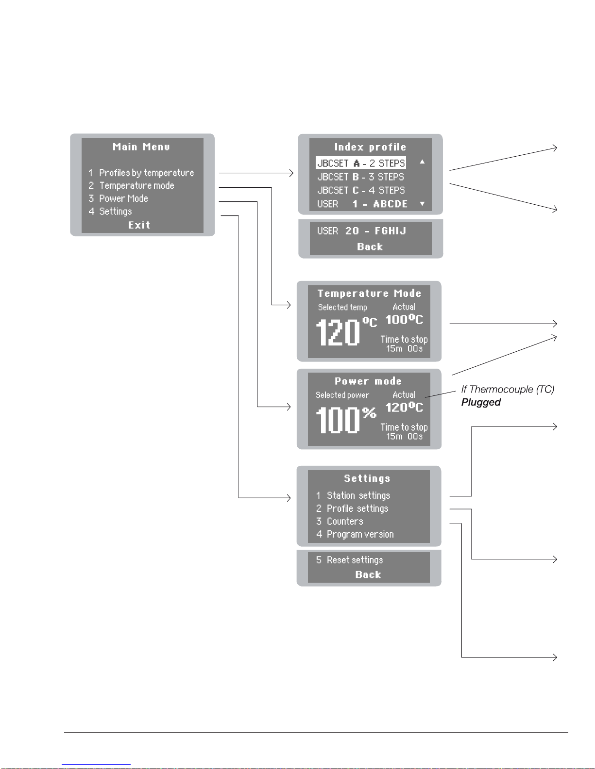
Power Mode
The unit works at the selected power or temperature during the defined time. These parameters can
be modified from the work screen by pressing the Enter button and the Edit parameters menu.
To see the current temperature you must plug the Thermocouple (TC) into the Control connector.
PCB reference
specifications:
FR4 1,6mm thick
and 2 layers. FR4 2,2mm thick
and 6 layers.
FR4 1,6mm thick
and 6 layers.
Profiles set using the low position of the PHS-SA Support (28 mm in height between the PCB and the heating area).
4

Recommended Guidelines
1. Place the Thermocouple (TC) as near as possible to the component being worked on.
2. If there are any sensitive components, use the Auxiliary Thermocouple as protection.
You can select the protection temperature in Station settings. If the selected temperature is
reached, the Heater Unit will stop the process and a warning message will be shown.
3. IPC* does not recommend exceeding ramp-up rates over 3 - 4 °C / sec (5 - 7 °F / sec) so as to
reduce the risk of thermal stress on the PCB.
* IPC was founded in the U.S. in 1957 as the Institute for Printed Circuits and is committed to becoming the
most recognized international industry association for the electronics manufacturing industry.
Fix the TC with Kapton Tape
Auxiliary Thermocouple (TC)
www.jbctools.com
5

Display Control
6

www.jbctools.com
7

Maintenance
Before carrying out maintenance, always allow the equipment to cool.
- Check periodically that the PHS-B is clean.
- Use a damp cloth when cleaning. Alcohol can only be used to clean the metal parts.
Clean
periodically
- Only if it is absolutely necessary and
if cleaning with isopropyl alcohol (IPA) is not
enough, it is recommended to use a scraper
to remove dirt in the glass area.
- Replace any defective or damaged parts.
Use original JBC spare parts only.
- Repairs should only be performed by a JBC
authorized technical service.
8

Safety
It is imperative to follow safety guidelines to protect health and prevent electric
shock, injury, fire or explosions.
- Do not use the units for any purpose other than PCB preheating. Incorrect use may cause fire.
- The mains cable must be plugged into approved bases. Make sure that it is properly grounded
before use. When unplugging it, hold the plug, not the wire.
- The temperature of accessible surfaces may remain high after the unit is turned off. Handle with care.
- Do not leave the appliance unattended when it is on.
- Do not cover the ventilation grills. Heat can cause inflamable products to ignite.
- Heat can cause inflamable products to ignite even when out of sight.
- Be careful with the remains of liquid tin. In contact with skin, it can cause burns.
- Avoid flux coming into contact with skin or eyes to prevent irritation.
- Be careful with the smoke produced when soldering.
- Keep your workplace clean and tidy. Wear appropriate protection glasses and gloves when
working to avoid personal harm.
- This appliance can be used by children over the age of eight as well as persons with reduced
physical, sensory or mental capabilities or lacking experience provided that they have been given
adequate supervision or instruction concerning use of the appliance and understand the hazards
involved. Children must not play with the appliance.
- Maintenance must not be carried out by children unless supervised.
www.jbctools.com
9

Specifications
IR Preheater
PHS-1B 120V. Input 120V 50/60Hz Fuse 8A
PHS-2B 230V. Input 230V 50/60Hz Fuse 4A
PHS-9B 100V. Input 100V 50/60Hz Fuse 8A
- Weight: 2,9 kg (6.39 lb)
- Dimensions (Heater Unit): 195 x 288 x 41,5 mm (7.68 x 11.34 x 1.63 in)
- Maximum Power: 500W
- Heating Area: 65 x 135 mm (2.56 x 5.31 in - 1 zone)
130 x 135 mm (5.12 x 5.31 in - 2 zones)
- Temperature Range: 50 - 250 °C (120 - 482 ºF)
- Temperature Measurement: Thermocouple type K
- JBCset temperature profiles: 3 profiles (2, 3 or 4 steps)
- User Profiles: 20 (up to 6 steps for each)
- Maximum work time: 600 min or indefinite
Complies with CE standards.
ESD protected housing.
10

Precalentador por Infrarrojos
Ref. PHS-B
www.jbctools.com
11

Composición
Los siguientes artículos deberían estar incluidos:
Power Cord
Cable de red .......................................... 1 unidad
Ref. 0009417 (100V/120V)
0009401 (230V)
Thermocouple
Termopar (Tipo K) ................................. 1 unidad
Ref. PH218
Kapton Tape
Cinta Kapton ......................................... 1 unidad
Ref. PH217
Manual .................................................. 1 unidad
Ref. 0017241
IR Preheater Precalentador por Infrarrojos .................................................................................. 1 unidad
Ref. PHS-1B (120V)
PHS-2B (230V)
PHS-9B (100V)
Heater Unit
Unidad calefactora
Console
Consola
Ref. PHS-B
IR Preheater
12
www.jbctools.com

Características
Conector de Pedal (opcional)
Ref. P-005
Áreas calefactoras
Toma de Red
Interruptor general
Fijadores para el
soporte PHS-SA
Unidad de Control Botón Inicio / paro
Conector para Termopar auxiliar (Tipo K)
Termopar
(Tipo K)
Ref. PH218
Conector USB-B a PC:
Actualice el software
Heater Unit
Unidad calefactora
Console
Consola
Zona A
Zone B
www.jbctools.com
13

Perfiles por Temperatura
El modo usual de ejecutar un perfil es utilizando el Termopar (TC) en el conector de Control.
JBC le ofrece 3 perfiles predefinidos (JBCset) y 10 perfiles listos para personalizar (User Profiles).
Funcionamiento
JBCset A
2 pasos
JBCset B
3 pasos
JBCset C
4 pasos
Recomendamos que para trabajos repetitivos, se ejecuten los perfiles sin Termopar: Una vez un
perfil cualquiera se ha ejecutado hasta el final, el sistema dispone de todos los datos del proceso
y pregunta si se desea salvar. En caso afirmativo se podrá ejecutar ese perfil sin tener el termopar
conectado. El proceso de calentamiento será idéntico siempre que se respeten las mismas
condiciones de trabajo.
Perfiles JBCset (JBCset profiles)
Hay 3 perfiles predefinidos por JBC: A, B y C. La diferencia entre ellos es el número de pasos:
2, 3 o 4. Cuanto más grueso sea su PCB y más capas contenga, más pasos serán necesarios
para obtener un calentamiento uniforme y progresivo.
Estos perfiles no son modificables pero pueden ser usados como plantilla para crear sus
propios perfiles (User Profiles).
Perfiles de Usuario
Puede crear sus propios perfiles a partir de los perfiles JBCset. Desde la pantalla de trabajo del
perfil, apriete el botón Enter y elija la opción Edit profile.
PCBs y
condiciones
de referencia:
FR4 de espesor
1,6mm y 2 capas.
FR4 de espesor
2,2mm y 6 capas.
FR4 de espesor
1,6mm y 6 capas.
Por qué Infrarrojos? La tecnología más eficiente para precalentar PCBs
Es el método más avanzado, eficiente y rentable para precalentar PCBs en cualquier trabajo de
soldadura o reparación. La poca masa térmica del elemento infrarrojo proporciona un control
excepcional del calor y de la temperatura del proceso. Esta tecnología ofrece una respuesta rápida,
altas tasas de calor y un calentamiento uniforme que garantiza los mejores resultados.
Modos de potencia
La unidad funciona a la potencia o temperatura seleccionada durante el tiempo establecido.
Estos parámetros pueden ser modificados desde la pantalla de trabajo apretando el botón Enter y
accediendo al menu Edit parameters.
Si desea ver la temperatura actual debe conectar el Termopar en el conector de Control.
Perfiles realizados utilizando la posición baja del soporte PHS-SA (28 mm de altura entre el PCB y el área calefactora).
14

Recomendaciones
Cinta Kapton para fijar el Termopar en el PCB
1. Coloque el Termopar tan cerca como sea posible del componente a trabajar.
2. Si hay algún componente sensible, use el Termopar Auxiliar como protección.
Puede seleccionar la temperatura de protección en el menú Station settings. Si la temperatura
llega a la establecida, se interrumpirá el proceso y mostrará un warning.
3. IPC* no recomienda exceder tasas de rampas por encima de los 3 - 4 °C / seg (5 - 7 °F / seg)
con el fin de reducir el riesgo de estrés térmico en los PCBs.
* IPC se fundó en USA en 1957 con el nombre de Institute for Printed Circuits con la intención de convertirse en
la asociación internacional más reconocida de la industria manufacturera electrónica.
Termopar Auxiliar (TC)
www.jbctools.com
15

Pantallas de control
16

www.jbctools.com
17

Mantenimiento
Antes de almacenar o de su mantenimiento, desconecte el equipo y déjelo enfriar.
- Compruebe periódicamente que el precalentador PHS-B esté limpio.
- Utilice un paño húmedo para limpiar. Sólo utilice alcohol para las partes metálicas.
Limpie
periódicamente
- Solo cuando sea absolutamente necesario
y si la limpieza con isopropanol (IPA) no es
suficiente, se recomienda el uso de una
rasqueta para limpiar la suciedad adherida en
la zona del cristal.
- Cambie cualquier pieza defectuosa o dañada.
Utilice solamente recambios originales de JBC.
- Cualquier reparación sólo podría ser realizada
por un servicio técnico oficial JBC.
18

Seguridad
- No utilice la unidad para otros fines que no sea el precalentamiento de PCBs. El uso incorrecto
puede causar fuego.
- El cable de red debe enchufarse en bases homologadas. Asegúrese de que está conectado a
tierra antes correctamente antes de su uso. Al desenchufarlo, tire del conector, no del cable.
- La temperatura de las superficies accesibles puede ser alta incluso cuando la unidad está
apagada. Manipule con cuidado.
- No deje el aparato desatendido cuando esté en funcionamiento.
- No cubra las rejillas de ventilación. El calor puede causar que los productos inflamables se enciendan.
- El calor puede causar que los productos inflamables se enciendan aunque no estén a la vista.
- Tenga cuidado con los restos de estaño líquido. En contacto con la piel, puede causar
quemaduras.
- Evite el contacto del Flux con la piel o los ojos para prevenir la irritación.
- Tenga cuidado con el humo producido al trabajar.
- Mantenga su lugar de trabajo limpio y ordenado. Use gafas y guantes de protección adecuados.
Así evitará cualquier daño.
- Este aparato puede ser utilizado por personas a partir de 8 años y también por aquellas
personas con movilidad reducida o capacidades físicas, sensoriales o mentales limitadas o
con falta de experiencia y conocimientos siempre y cuando reciban supervisión o instrucciones
relativas al uso del aparato de una manera segura y entiendan los riesgos que implica. Los niños
no deben jugar con el aparato.
- Los niños no deberán realizar tareas de mantenimiento sin supervisión.
Es necesario seguir estas directrices de seguridad para proteger su salud y
prevenir cualquier choque eléctrico, heridas, fuego o explosiones.
www.jbctools.com
19

Especificaciones técnicas
IR Preheater · Precalentador por Infrarrojos
PHS-1B 120V. Entrada 120V 50/60Hz Fusible 8A
PHS-2B 230V. Entrada 230V 50/60Hz Fusible 4A
PHS-9B 100V. Entrada 100V 50/60Hz Fusible 8A
- Peso: 2,9 kg (6.39 lb)
- Dimensiones (Unidad calefactora): 195 x 288 x 41,5 mm (7.68 x 11.34 x 1.63 in)
- Potencia máxima: 500W
- Área calefactora: 65 x 135 mm (2.56 x 5.31 in - 1 zona)
130 x 135 mm (5.12 x 5.31 in - 2 zonas)
- Rango de temperatura: 50 - 250 °C (120 - 482 ºF)
- Medición de temperatura: Termopar Tipo K
- Perfiles predefinidos por JBC (JBCset): 3 perfiles (2, 3, 4 pasos)
- Perfiles de usuario: 20 (hasta 6 pasos para cada uno)
- Tiempo de trabajo máximo: 600 min o indefinido
Cumple con las normativas CE.
Protección ESD.
20
This manual suits for next models
2
Table of contents
Languages:
Other jbc Soldering Gun manuals