JOVY Systems iSolder-40 User manual

1
JOVY SYSTEMS®
iSolder-40
User Manual
Rev. 1.00

2
Thank you for purchasing Jovy systems iSolder-40 soldering station.
Please read this manual before operating the iSolder-40.
Keep the manual in accessible place for future reference
User Manual

3
Index
Warnings and precautions ---------------------- 4
Specification ---------------------------------------- 5
Initial setup ----------------------------------------- 6
Operating modes guideline---------------------- 9
Tip care and selection ---------------------------- 11
Hints and Tricks ------------------------------------ 13
Warranty--------------------------------------------- 15

4
Warnings and precautions
The tip temperature can be > 400°C. Please note; ignoring the
precautions may lead to injury to users or damage the
i
Solder-40
Do not touch or change the tip while operating the
i
Solder-40.
Do not use the
i
Solder-40 near flammable items
Do not use the solder station for any function other than De-
soldering or soldering the electronic/electrical components. (Do
not use it with wood, wax, plastic, etc…)
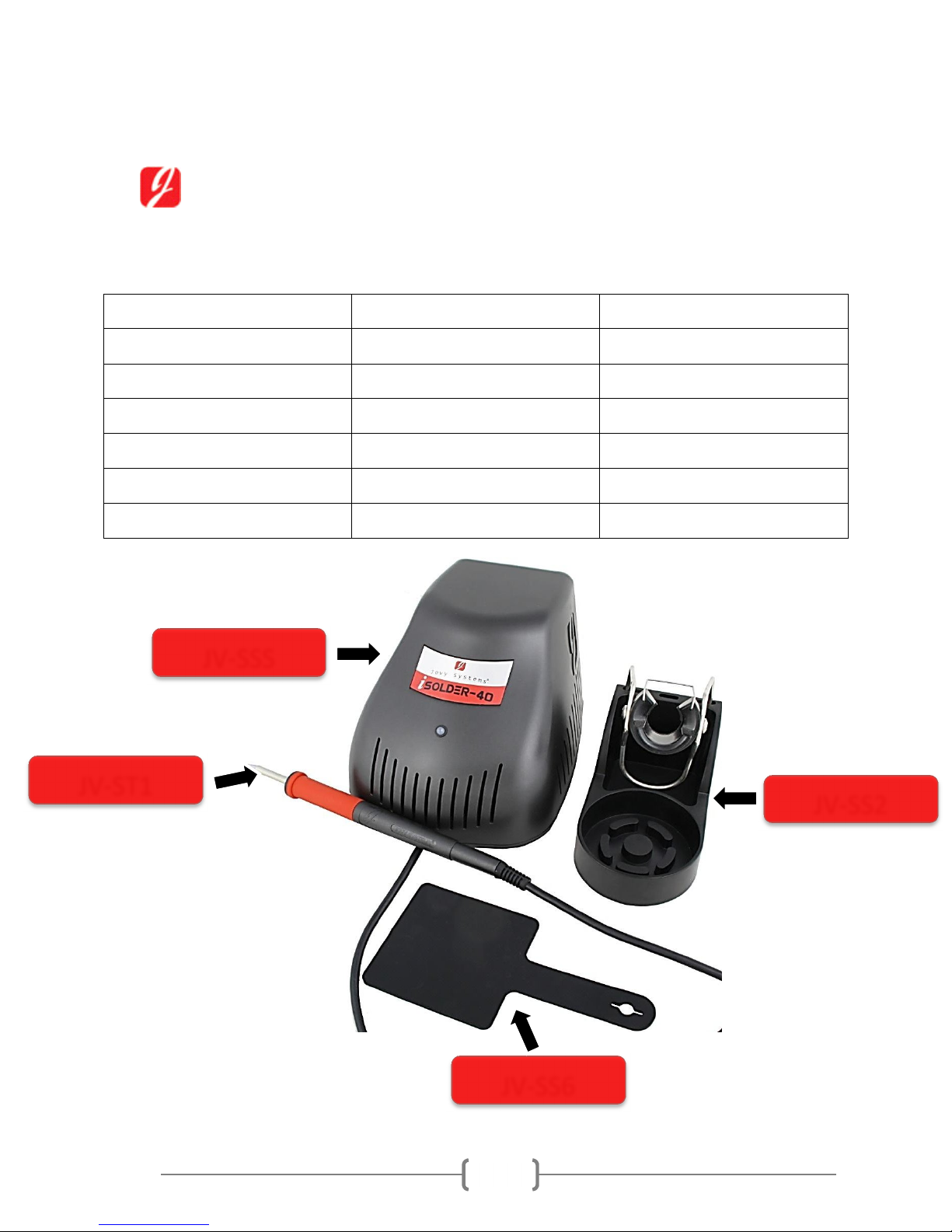
Use only tips and parts supplied by JOVY Systems®.
Make sure that the tip does not touch any object while in
operating mode. It negatively affects the tip sensitivity.
Use in a well-ventilated work space and preferably use a smoke
absorber appliance.
Do not use the equipment or the hand piece with wet hands.
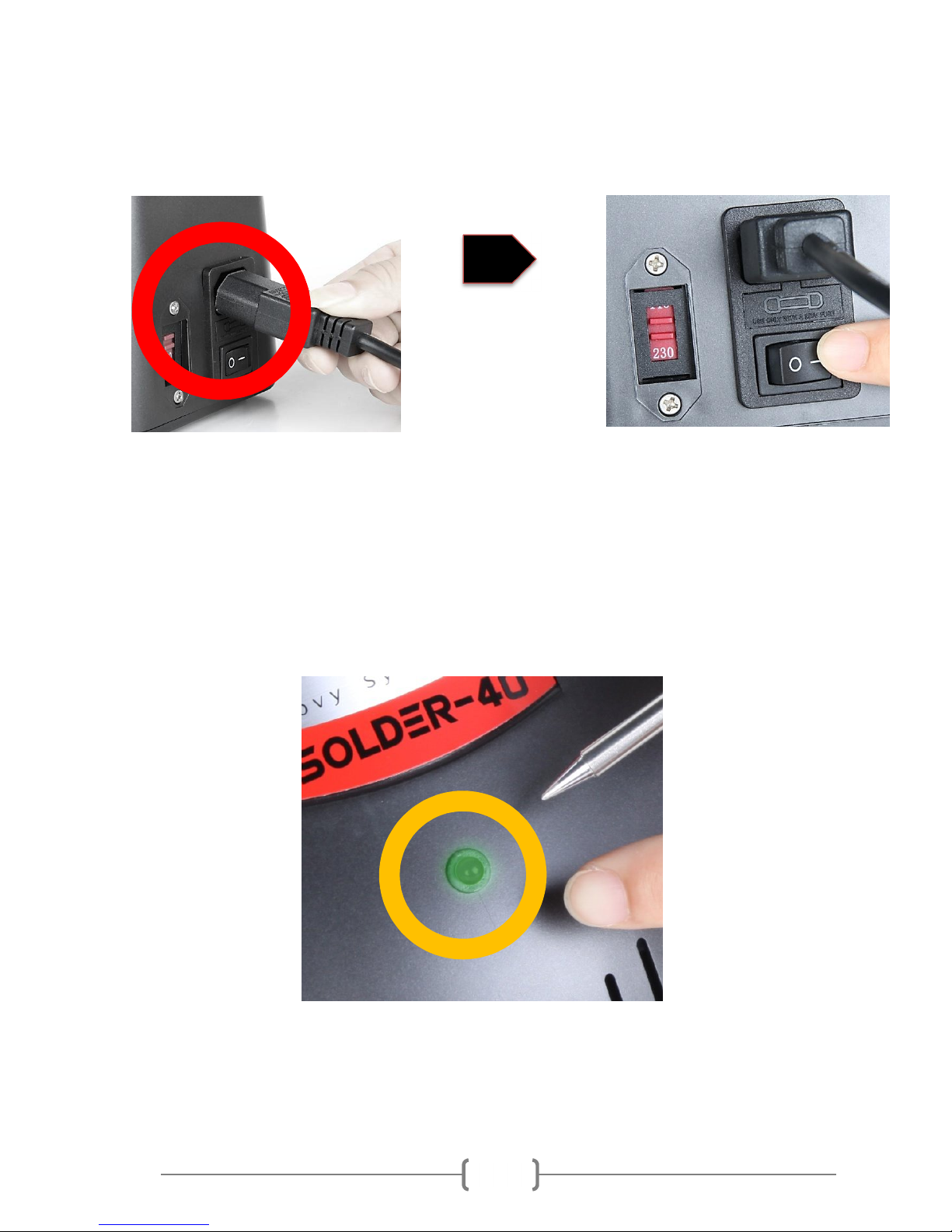
Connect only to properly grounded outlets to prevent risk of
electric shock or equipment malfunction.
Always place hand-piece back into the holder to prevent
accidental burning of oneself or surrounding objects.
The
i
Solder-40 is not intended for use by persons (including
children) with reduced physical, sensory or mental capabilities.
As well, persons with lack of experience and knowledge, unless
they have been given supervision or training concerning use of
the soldering station by a person responsible for their safety.
Safety precautions:
Use the protective pad to exchange the tip and do not expose or touch the tip by
your skin.
Keep a distance from the working space during the rework process, reworking
process might produce unwanted smoke toward your eyes and lungs.

5
Specifications
Power supply technical specifications:
Ambient Operating Temperature
20
-
40°C
Maximum Enclosure Temperature
53
°C
Input Line v
oltage
11
5
VAC/60Hz
–
2
3
0VAC/50Hz
Output voltage
24VAC
Power Consumption
100
Watts max.
Dimensions
(L*W*
H) mm.
188 x 144 x 120
Power chord length (Plug type)
1.8 meters
Hand piece technical specifications:
Tip
-
to
-
Ground Potential
<
2 mV
Tip
-
to
-
Ground Resistance
<
2 Ohm
Hand piece cord
Length
1.5
meters
Hand pi
ece
Length
158 mm
iSolder-40 is ESD Safe Equipment

6
Initial set-up
Packing list:
Item Code Quantity
Solder Station JV-SSS 1
Main tip JV-ST1 1
Hand piece holder JV-SS2 1
Cleaning sponge JV-SS3 1
Protective Pad JV-SS6 1
Power cord JV-SS7 1
JV
-
ST1
JV
-
SS6
JV
-
SSS
JV
-
SS2

7
How to use:
1- Unpack the iSolder-40 and select the
proper voltage range from the voltage
selector (110VAC/60Hz or 220VAC/50Hz).
2- Place and arrange the iSolder-40 with all other parts in a convenient location in
your workspace.
3- Insert the desired tip into the hand piece to end – fastening click heard – by using
the protective pad, steps as shown in figure 1 and 2. (For more information
about tips see tip care and selection page 11)
Figure 1 Figure 2

8
4- Plug the power cord into electricity supply and switch on the iSolder-40.
5- If the tip is inserted correctly a green led indicator will start flashing – Heating up
mode. If the tip inserted wrongly the led color will be red.
6- Wait for the led indictor light to become green and start using the solder station
for soldering process.

9
Operating modes Guideline
Recognize the operating mode and solder station status by the led
indicator color and state.
Attention!
When the tip is disconnected from the hand piece, the controller gives a
continuous red light indication on the led indicator.
When the controller is active and sensing, the fast flashing Green Led will be
seen from time to time.
1)
Heating up mode
When the tip is fully inserted into the hand piece, the iSolder-40 controller starts to
detect the tip.
The indicator of this state is a flashing green led.
2)
Operating mode
When the tip is ready to be used the green led stop flashing and becomes steady green.
The indicator of this state is a steady green led.

10
3)
Sleep mode
When the iSolder-40 controller senses no usage for 5 minutes, the iSolder-40 starts the
sleep mode for saving power.
The indicator of this mode is a flashing red led (short on; short off).
To get out from sleep mode and turn to operating mode, move the hand
piece from the holder and wait until the iControl automatically senses and
update the status from Sleep to Operating mode.
4)
Power saving mode
*
After 10 minutes in the sleep mode, the iSolder-40 will turn to the power
saving mode, where no power is delivered to the tip at all and the tip
temperature drops down to room temperature.
The power saving mode is a safety mode where the device can get out of it
by moving the hand piece to left or right direction.
Also to shift from operating mode switch Off/On the iSolder-40
The indication of this state is a flashing red led (short on; short off).
*The difference between the sleep mode led color indicator and the auto shut-down mode led color
indicator is the speed of flashing.
For sleep mode the led red flash speed is Off/on in seconds is 1/1.
For standby mode the led flash speed is Off/on in seconds is 5/1.

11
Tip care and selection
Available tips for iSolder-40:
JV
-
TP1
JV
-
TP2
JV
-
TP3
JV
-
TP4
JV
-
TP5
JV
-
TP6

12
Guide for tip selection:
Good
Too light
Too heavy
The ideal tip choice is the tip which its active area should cover completely the solder
area. The best percentage of soldering area to tip active area is 2:1.
Tip care guide for longer life time:
- Clean the tip by wiping it with a wet sponge and slightly drag it out after each
use.
- Never use excessive mechanical force for the tip when soldering.
- Soldering tip oxidation should quickly be cleaned and removed; it negatively
affects the tip sensitivity.
- Use the wire mesh to remove bulk solder materials remaining over the tip after
each usage.

13
Hints and Tricks
Tip oxidation removal:
Firstly, clean the tip using a wet sponge then clean with wire brush. Secondly, use
a tip re-activator chemical to remove hard residues and oxidation, and finally re-
tinning using solder wire (flux cored).
Make sure that the tip type is compatible to the application – as explained above
in tip selection section – with the solder material mass to avoid process failure,
tip damage and oxidation.
Apply the tip to small part of solder wire before you start soldering or de-
soldering.
Wet the sponge by distilled water.
Note: Sulfur and other minerals in Tap-water cause fast tip oxidation.
Keeping the tip clean and shine, enhances the sensitivity and performance of the
tip.

14
Sample applications for the iSolder-40 main tip
SMT Any type of soldering material
Heavy junctions
THT

15
Warranty
Please visit Jovy systems web page (www.Jovy-systems.com/contact) on support form
tab, fill in subject with product registration and make sure you write the iSolder-40
serial number.
You may also contact the local representative or distributor for Jovy systems® for
pricing and availability.
Jovy Systems® warrants the iSolder-40 against any manufacturing defects for
one (1) year from the date of purchase by the original owner. If the product
defected within the warranty period, it will be repaired or replaced free of
charge.
This warranty excludes normal maintenance and shall not apply to any opened,
misused, abused, altered or damaged items.
The warranty period will start from the date of purchase. If the date of purchase
cannot be substantiated the date of manufacture will be used as the start of the
warranty period.
Table of contents
Other JOVY Systems Soldering Gun manuals