Ausgabe 01.02.2017 Copyright by Joy-IT 5
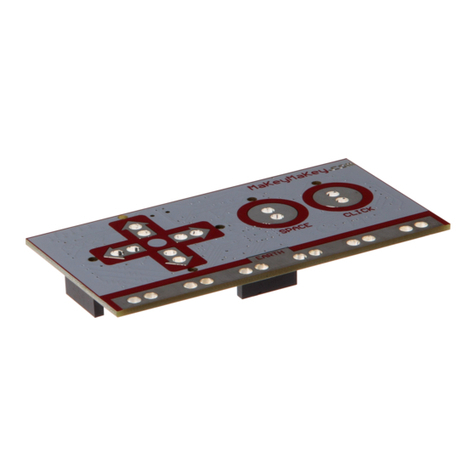
The channel-numbers are wrien on the backside of
the board.
The 3 PINs of each channel are, from boom to top,
ground line, voltage line and signal line [GND | V+ |
PWM].
Simply put the board onto the GPIO-PINs of your
Arduino and the cables of your 5V-Servo-Motors on
the Channel-PINs.
An addional power supply, by cable or a 5V coaxial
power connector, is required.
To prevent sudden voltage drops, a capacitor is
mounted on the board.
If this capacitor is insucient in special cases, you are
able to connect another capacitor in parallel with the
intended connecon.
Image 3: board backside
Security information:
To protect against polarity reversal, please note the markings on the inputs of the board (+ and - symbol).
Polarity reversal can damage the board, the connected Arduino and other periphery.
The connected motors, and the generated movement, can pose a risk.
We recommend to remain at a safe distance and take acons so that noone can encounter with moving parts.
This applies in parcular for children.
The used power supply has to be adequate for the performance of the motors. A weak power supply is oen
recognizable by stuering motors. The motors should always perform a smooth moon.
We recommend to use our 4.8A power supply RB-Netzteil2 which provides 24W connous output.
Aer connecng the board to your Arduino, an addional power supply and the servo-motors, the board is
ready to use.


