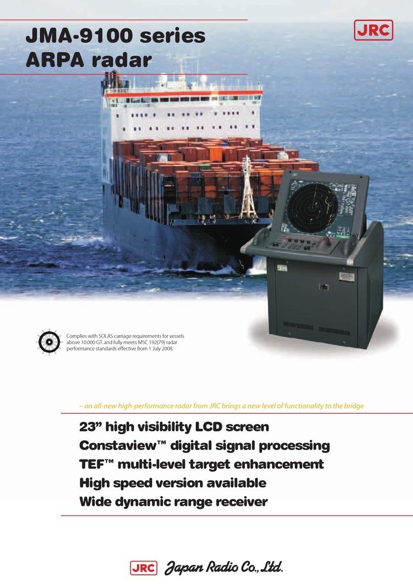
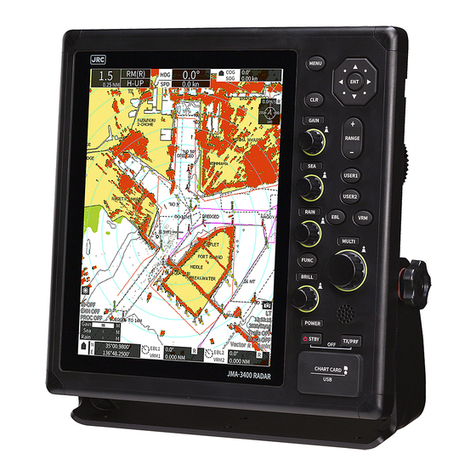
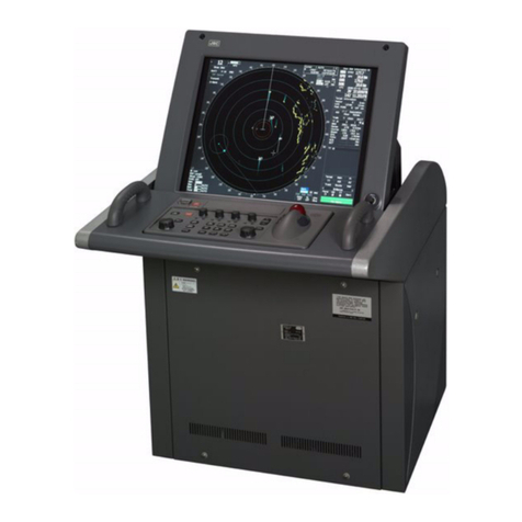
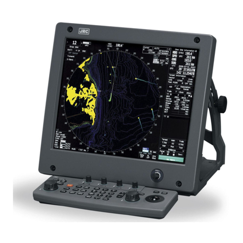
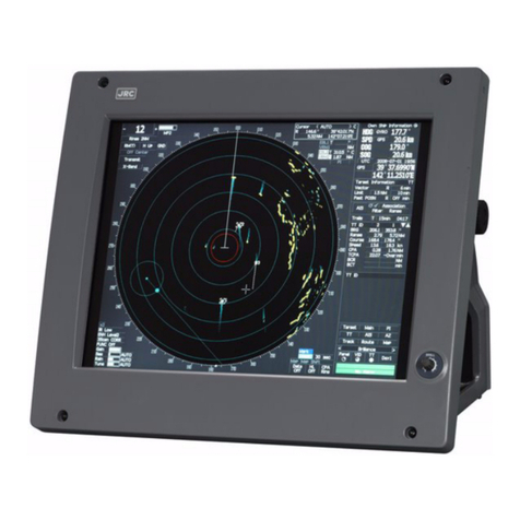
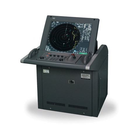
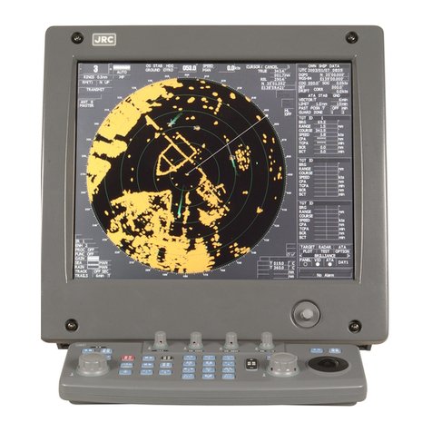
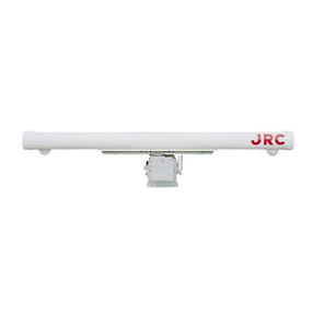
JRC JMR-7230-S3 User guide

JMR-7230-S3/S
JMR-7225-7X3/9X3/6X/9X/6XH
JMR-7210-6X/6XH
JMR-7272-S
JMR-7282-S/SH
JMR-9230-S3/S
JMR-9225-7X3/9X3/6X/9X/6XH
JMR-9210-6X/6XH
JMR-9272-S
JMR-9282-S/SH
Marine Radar Equipment
Quick Operation Guide
1 Introduction ................................................................. 1
1.1 Read Before Use............................................................1
2 Basic Operations......................................................... 2
2.1 Powering On and Starting ..............................................2
2.2 Finishing and Stopping Operation ..................................4
2.3 Adjusting Screen Brightness...........................................4
2.4 Changing the Observation Range ..................................6
2.5 Adjusting Gain...................................................................7
2.6 Removing Sea Clutters...................................................8
2.7 Removing Rain/Snow Clutters......................................10
2.8 Using the Electronic Cursor (EBL1/EBL2) ....................12
2.9
Using Variable Range Marker (VRM1/VRM2)
.....................13
2.10
Setting Up the Measurement Reference Point of the
Electronic Bearing Line and Variable Range Marker
............14
2.11
Switching the Transmission Pulse Length
...........................15
2.12 Switching the Azimuth Mode ........................................15
2.13 Setting the Motion Mode...............................................16
2.14 Displaying Radar Trail ..................................................17
3 Operation of Target Tracking .................................... 19
3.1 Acquiring a Target ........................................................19
3.2 Displaying the Information of Tracking Targets ............19
3.3 Erasing Tracked Targets ..............................................20
4 AIS Operation............................................................ 21
4.1 Setting Up the AIS Display Function.............................21
4.2 Activating an AIS Target...............................................21
4.3 Displaying the AIS Information .....................................22
4.4 Deactivating an AIS Target...........................................22
5 Operation Common to Target Tracking and AIS....... 23
5.1 Setting Up Vectors........................................................23
5.2
Setting Up the Collision Determining Condition
...........................24
6 Other Operations ...................................................... 25
6.1 Stopping an Alert..........................................................25
6.2 Acknowledging an Alert ................................................26
6.3 Operation with the Software Keyboard .........................27
㻌
㻌
㻌1
1 Introduction
1.1 Read Before Use
About the Quick Operation Guide
For more details, please read the Operation Manual.
Please keep this Quick Operation Guide in an easily accessible place.
About the Radar
Use the radar solely as a navigation aid. Also, the final decision of maneuvering must be made by the
person who maneuvers the ship. If the final decision on maneuvering is solely made based on the
information displayed by the radar, it may cause accidents such as collision and running aground.
About sea clutter suppression
Do not adjust the sea clutter suppression function until all sea clutters are erased in the close distance
range.
Otherwise, targets such as vessels and dangerous objects will be suppressed in addition to echoes
from waves, causing to interfere detection.
When using the sea clutter suppression function, always perform optimum suppression adjustment.
About rain/snow clutter suppression
Do not adjust the rain/snow suppression function excessively. Otherwise, targets such as vessels and
dangerous objects will be suppressed in addition to echoes from rain and snow, causing to interfere
detection.
When using the rain/snow clutter suppression function, always perform optimum suppression
adjustment.
About the target tracking function
Use the target tracking function solely as a navigation aid. Also, the final decision of maneuvering must
be made by the person who maneuvers the ship. If the final decision on maneuvering is solely made
based on the information acquired from the target tracking function, it may cause accidents.
Vectors, target numeric data, alarms and other information displayed by the target tracking function
may contain errors. Note that targets which cannot be detected by the radar can neither be acquired
nor tracked.
If the final decision on maneuvering is solely made based on the information displayed by the radar, it
may cause accidents such as collision and running aground.
7ZPNA4395

2 Basic Operations
2.1 Powering On and Starting
1 Make sure that the ship's power is on.
2 Press the Power button on the operation unit.
The Power button illuminates and the Start screen appears.
After the Start screen appears, the Task menu appears next after a while.
3 Click the "Collision Avoidance (RADAR)" button on the Main menu.
The RADAR screen appears.
When a magnetron radar antenna is connected, the preheat time is displayed in the center of
the screen.
2

The standby/transmission changeover button of the radar system information is switched to
"Preheat".
4 Wait until preheating completes.
When the preheat time expires, the Preheat Time screen disappears and the
standby/transmission changeover button of the radar system information is switched from
"Preheat" to "Standby".
5 Click the standby/transmission changeover button.
Radar transmission starts and the radar antenna rotates.
The display of the standby/transmission changeover button is switched from "Standby" to
"Transmit".
Standby/transmission
changeover button
When a magnetron radar
antenna is connected
When a fixed radar antenna
is connected
Standby/transmission
changeover button
Standby/transmission
changeover button
3

2.2 Finishing and Stopping Operation
1 Click the standby/transmission changeover button of the radar signal information.
Radar transmission stops and the rotation of the radar antenna stops.
The display of the standby/transmission changeover button is switched from "Transmit" to
"Standby".
2 Press the Power button on the operation unit.
The power to this equipment stays off.
2.3 Adjusting Screen Brightness
Adjust the screen to an easy to view state by operating the "MULTI" dial.
2.3.1 When "DISP Brightness" is being displayed
in the Key Assignment Indication Area (key
allocation display area)
1 Adjust the screen brightness by rotating the "MULTI" dial to the right or left.
The entire screen becomes brighter when the dial is rotated to the right.
The entire screen becomes darker when the dial is rotated to the left.
"MULTI" dial
Key Assignment Indication Area
(key allocation display area)
4

2.3.2 When "DISP Brightness" is not being
displayed in the Key Assignment Indication
Area (key allocation display area)
1 Press the “M ULTI” dial for a long time.
The Display Brightness function will be assigned to the “MULTI” dial.
2 Adjust the screen brightness by turning the “MULTI” dial to the left or right.
The entire screen becomes brighter when the dial is rotated to the right.
The entire screen becomes darker when the dial is rotated to the left.
5

2.4 Changing the Observation Range
1 Click the Range Scale button of the presentation and mode information, and then
select a range from the pop-up menu that appears.
A wider range can be observed by widening the observation range.
When the observation range is narrowed down, the area near own ship can be observed by
enlarging it.
Range Scale button
6

2.5 Adjusting Gain
1 Continue clicking the slider of the "Gain" slider control of the radar signal information,
and specify the gain by rotating the trackball.
If there is the optional keyboard operation unit, the operation of the "GAIN" dial is also
possible.
Moving the slider to the right increases the gain.
Moving the slider to the left decreases the gain.
When the gain is increased, the distance where radar images can be observed is widened.
"Gain" Slider Control
7

2.6 Removing Sea Clutters
2.6.1 When Using the Manual Sea Clutter
Suppression Function
1 Click the Automatic Sea Clutter Suppression button.
The display of the Automatic Sea Clutter Suppression button changes to "MAN" (Manual).
2 Continue clicking the slider of the "Sea" slider control of the radar signal information,
and adjust the amount of images displayed from reflections of sea clutters on the
screen by rotating the trackball to facilitate observation.
If there is the optional keyboard operation unit, the operation of the "SEA" dial is also
possible.
Moving the slider to the right decreases the amount of images reflected from sea clutters.
Moving the slider to the left increases the amount of images reflected from sea clutters.
The sea clutter suppression function decreases the amount of images reflected from sea clutters by
lowering the gain in short distances.
"Sea" Slider Control
Automatic Sea Clutter
Suppression button
8

2.6.2 When Using the Automatic Sea Clutter
Suppression Function
1 Click the Automatic Sea Clutter Suppression button.
The display of the Automatic Sea Clutter Suppression button changes to "AUTO" (Automatic).
2 Click the slider of the "Sea" slider control, and adjust the amount of images displayed
from reflections of sea clutters on the screen by rotating the trackball.
If there is the optional keyboard operation unit, the operation of the "SEA" dial is also
possible.
Even during automatic sea clutter suppression, fine adjustment of the amount of images can be
performed manually.
Canceling Automatic Sea Clutter Suppression
1 Click the Automatic Sea Clutter Suppression button.
The display of the Automatic Sea Clutter Suppression button changes to "MAN" (Manual).
Automatic Sea Clutter
Suppression button
9

2.7 Removing Rain/Snow Clutters
2.7.1 When Using the Manual Rain/Snow Clutter
Suppression Function
1 Click the Automatic Rain Clutter Suppression button.
The display of the Automatic Rain Clutter Suppression button changes to "MAN" (Manual).
2 Continue clicking the slider of the "Rain" slider control of the radar signal information,
and adjust the amount of images displayed from reflections of rain/snow clutters on
the screen by rotating the trackball to facilitate observation.
If there is the optional keyboard operation unit, the operation of the "RAIN" dial is also
possible.
Moving the slider to the right decreases the amount of images reflected from rain/snow clutters.
Moving the slider to the left increases the amount of images reflected from rain/snow clutters.
The rain/snow clutter suppression function decreases the amount of images reflected from rain/snow
clutters.
Since this function also has an effect to reduce reflections from sea clutters, it is effective to use it
together with the sea clutter suppression function.
"Rain"
Slider Control
Automatic Rain Clutter Suppression
button
10

2.7.2 When Using the Automatic Rain/Snow Clutter
Suppression Function
1 Click the Automatic Rain/Snow Clutter Suppression button.
The display of the Automatic Rain Clutter Suppression button changes to "AUTO" (Automatic).
2 Click the slider of the "Rain" slider control, and adjust the amount of images displayed
from reflections of rain/snow clutters on the screen by rotating the trackball.
Even during automatic rain/snow clutter suppression, fine adjustment of the amount of images
can be performed manually.
Canceling Automatic Rain/Snow Clutter Suppression
1 Click the Automatic Rain/Snow Clutter Suppression button.
The display of the Automatic Rain Clutter Suppression button changes to "MAN" (Manual).
Automatic Rain Clutter Suppressio
n
button
11

2.8 Using the Electronic Cursor
(EBL1/EBL2)
1 Click either the "EBL1" or "EBL2" button of the Navigation Tools.
Either EBL1 or EBL2 is placed in the operating mode and the display of the button changes
from "OFF" to the azimuth position.
2 Move the cursor to the azimuth you want to set up inside the PPI.
The EBL moves according to the movement of the cursor and the button's azimuth position
display also changes.
3 Click.
The EBL is fixed in position.
To move the measurement reference point of the EBL
1 Click the EBL button you want to set up and activate the operating state.
The display of the EBL button you clicked changes from "OFF" to the azimuth position display of
the measurement reference point.
2 Click one of the Measurement Reference Point buttons for the EBL in the operating
state, and set the measurement reference point to either "C" or "D".
3 Click on a point where you want to set as the measurement reference point of the EBL.
The measurement reference point of the EBL you selected is confirmed.
To return the measurement reference point of the EBL to Own Ship's Position
1 Click the EBL button you want to set up and activate the operating state.
The display of the EBL button you clicked changes from "OFF" to the azimuth position display of
the measurement reference point.
2 Click one of the Measurement Reference Point buttons for the EBL in the operating
state, and set the measurement reference point to "blank".
3 Click on a point where you want to set as the measurement reference point of the EBL.
The measurement reference point of the EBL you selected becomes own ship's position.
"EBL2"
Button
"EBL1"
12

2.9
Using Variable Range Marker (VRM1/VRM2)
1 Click either the "VRM1" or "VRM2" button of the Navigation Tools.
Either VRM1 or VRM2 is placed in the operating mode and the display of the button you clicked
changes from "OFF" to the distance position display.
2 Move the cursor to the distance you want to set up inside the PPI.
The VRM moves according to the movement of the cursor and the button's distance position
display also changes.
3 Click.
The VRM is fixed in position.
"VRM1"
"VRM2"
13

2.10 Setting Up the Measurement Reference
Point of the Electronic Bearing Line and
Variable Range Marker
The measurement reference point of this equipment's electronic bearing line (EBL) and variable range
marker (VRM) can be selected from the following three types. Set up a measurement reference point
according to usage.
Blank (CCRP): Sets a measurement reference point at own ship's position (CCRP).
C (Carried): Fixes a measurement point on the screen.
D (Dropped): Fixes a measurement point with longitude and latitude.
2.10.1 Moving the measurement reference point of
the EBL/VRM
1 Click the EBL or VRM button you want to set up and activate the operating state.
The display of the VRM button you clicked changes from "OFF" to the azimuth position
display and range display of the measurement reference point.
2 Click one of the Measurement Reference Point buttons for the EBL/VRM in the
operating state, and set the measurement reference point to either "C" or "D".
3 Click on a point where you want to set as the measurement reference point of the
EBL/VRM after moving the cursor inside the PPI.
The measurement reference point of the EBL/VRM you selected is confirmed.
2.10.2 Returning the measurement reference point
of the VRM to Own Ship's Position
1 Click one of the Measurement Reference Point buttons for the EBLVRM in the
operating state, and set the measurement reference point to "blank".
The measurement reference point of the EBL/VRM you selected becomes own ship's position.
Measurement Reference Buttons
14

2.11
Switching the Transmission Pulse Length
1 Click the transmission pulse witch changeover button of the radar system information.
Each time the button is clicked, the transmission pulse witch changes.
Example: "MP1"→"MP2"→"LP1"→"LP2"
2.12 Switching the Azimuth Mode
1 Click the Azimuth Mode button of the presentation and mode information.
2 Select the azimuth mode from "N UP", "H UP", "C UP", "C UP(Angle Setting)" and "W
UP".
The azimuth mode switches.
* [W UP] is in a state in which to load the route,
motion mode is displayed only in the case of [RM (T)] or [RM (R)].
Azimuth Mode Button
Transmission Pulse Width
Changeover Button
15

2.13 Setting the Motion Mode
2.13.1 Switching the Motion Mode
1 Select the motion mode from "TM", "RM(T)", and "RM(R)".
The motion mode switches.
2.13.2 Setting Up Own Ship's Position in the "TM"
(True Motion) Mode
1 Click the Motion Mode button of the presentation and mode information.
2 Select "TM Reset" from the list of motion modes.
Own ship's position is reset in the same way as when switching from relative motion display to
true motion display, and own ship starts moving from that position.
Motion Mode Button
16

2.14 Displaying Radar Trail
2.14.1 Changing the Trail Length
1 Click the Radar Trail Length Changeover button.
2 Select a radar trail length.
2.14.2 Erasing a Radar Trail
1 Click the "CLR" (Clear Radar Trails) button.
A confirmation dialog box appears.
2 Click the "OK" button.
All the trails are erased and drawing of trails start from the initial state.
Radar Trail Length
Changeover Button
"CLR" (Clear Radar
Trails) Button
17

2.14.3 Changing the display Mode of Radar Trails
1 Click the radar trail true/relative changeover button.
Each time the button is clicked, the radar trail display mode switches between "T" and "R".
"T": (True motion trail)
"R": (Relative motion trail)
Radar Trail True/Relative
Changeover Button
18
Other manuals for JMR-7230-S3
2
This manual suits for next models
23
Table of contents
Other JRC Marine Radar manuals

JRC
JRC JMA-9900 Series User manual

JRC
JRC JMA-7133-SA User manual

JRC
JRC JMA-5300 Series User manual

JRC
JRC JAN-701B - User manual

JRC
JRC JMA-9922-6XA User manual

JRC
JRC JMA-1032 User manual

JRC
JRC JMA-7110-6XA User manual

JRC
JRC JMA-5322-6HS User manual

JRC
JRC JMA-7710-6 User manual

JRC
JRC JMR-7230-S3 User manual