manuals.online logo
Brands
  1. Home
  2. •
  3. Brands
  4. •
  5. JRC
  6. •
  7. Water Filtration System
  8. •
  9. JRC NSVS778 User manual

JRC NSVS778 User manual

Other JRC Water Filtration System manuals

JRC NSVS1203 User manual

JRC

JRC NSVS1203 User manual

JRC NSVS1204 User manual

JRC

JRC NSVS1204 User manual

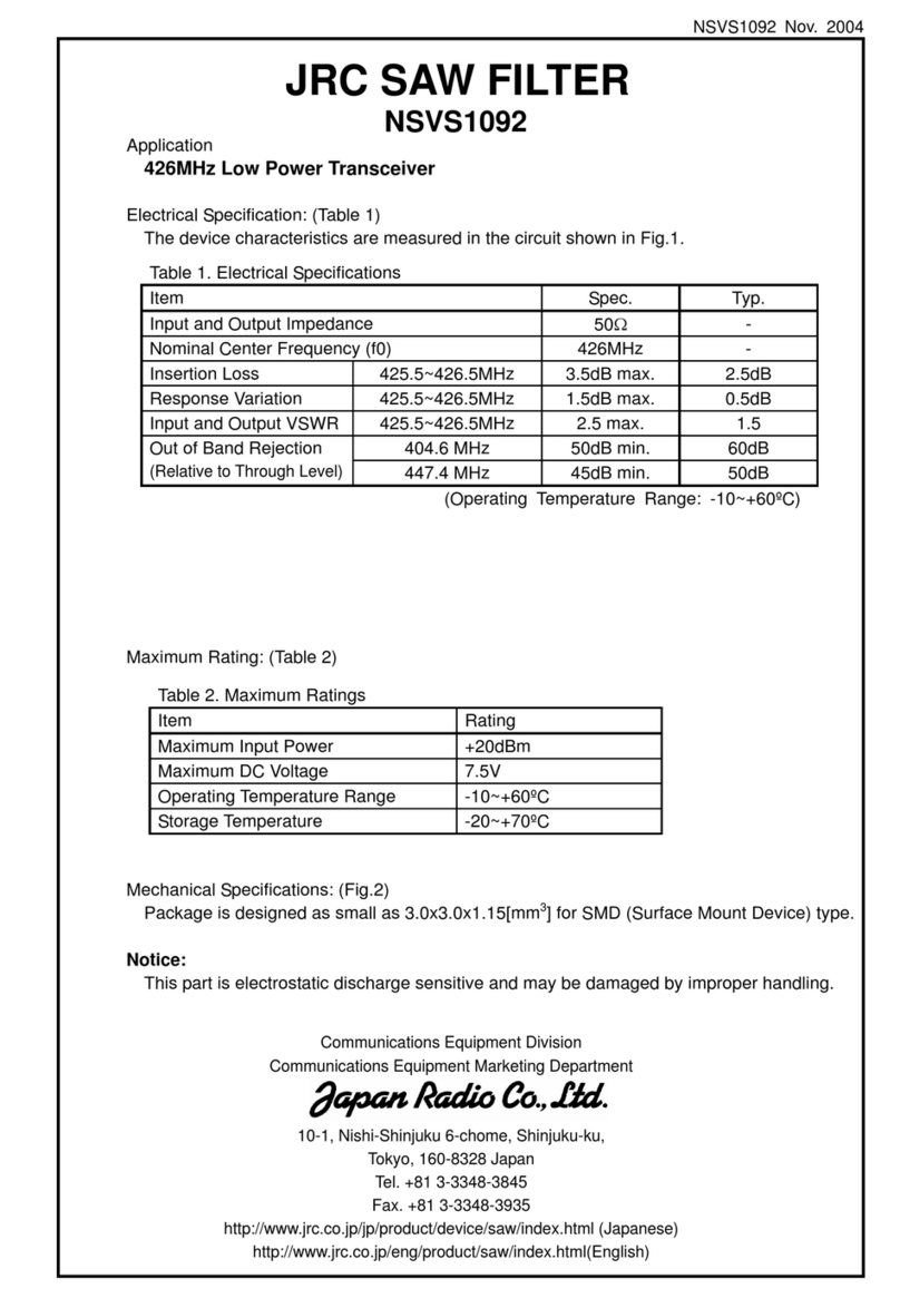
JRC NSVS1092 User manual

JRC

JRC NSVS1092 User manual

JRC NSVA253 User manual

JRC

JRC NSVA253 User manual

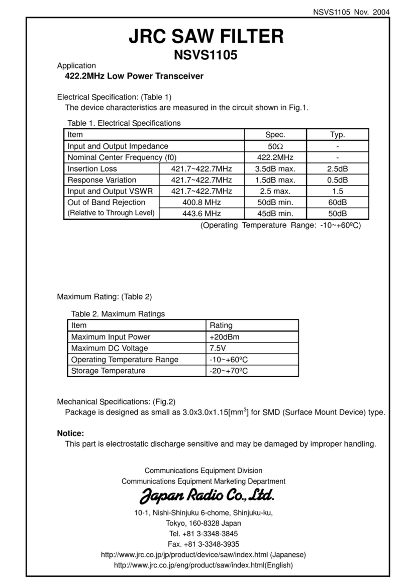
JRC NSVS1105 User manual

JRC

JRC NSVS1105 User manual

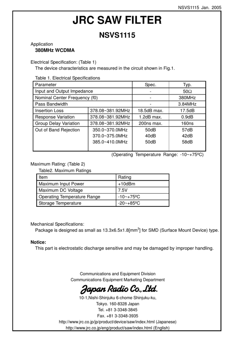
JRC NSVS1115 User manual

JRC

JRC NSVS1115 User manual

JRC NSVS1152 User manual

JRC

JRC NSVS1152 User manual

JRC NSVS1154 User manual

JRC

JRC NSVS1154 User manual

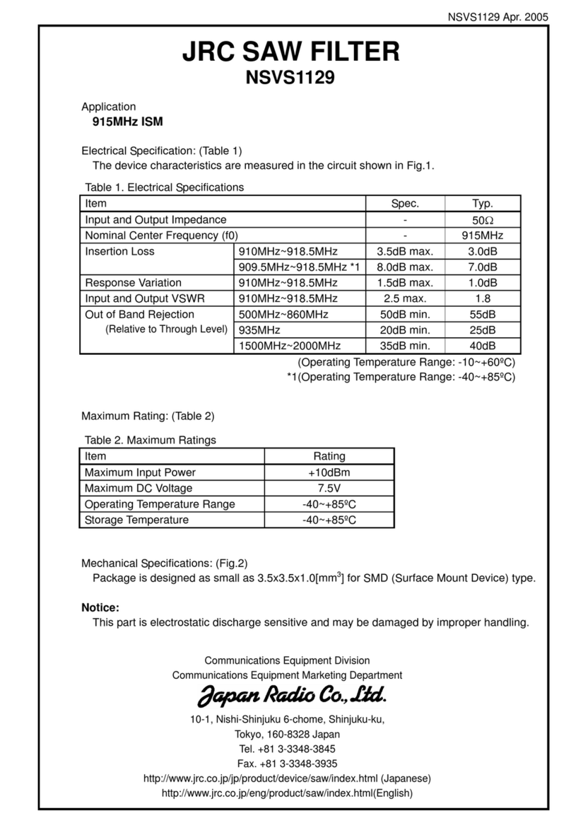
JRC NSVS1129 User manual

JRC

JRC NSVS1129 User manual

JRC NSVS1245 User manual

JRC

JRC NSVS1245 User manual

JRC NSVS1120 User manual

JRC

JRC NSVS1120 User manual

JRC NSVS1207 User manual

JRC

JRC NSVS1207 User manual

JRC NSVS616 User manual

JRC

JRC NSVS616 User manual

JRC NSVS1174 User manual

JRC

JRC NSVS1174 User manual

JRC NSVS1058 User manual

JRC

JRC NSVS1058 User manual

JRC NSVS676 User manual

JRC

JRC NSVS676 User manual

JRC NSVS1093 User manual

JRC

JRC NSVS1093 User manual

JRC NSVA300 User manual

JRC

JRC NSVA300 User manual

JRC NSVA254 User manual

JRC

JRC NSVA254 User manual

JRC NSVS614 User manual

JRC

JRC NSVS614 User manual

JRC NSVS1089 User manual

JRC

JRC NSVS1089 User manual

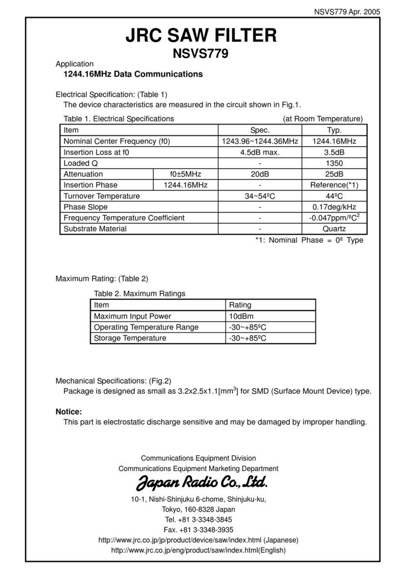
JRC NSVS779 User manual

JRC

JRC NSVS779 User manual

JRC NSVS1237 User manual

JRC

JRC NSVS1237 User manual

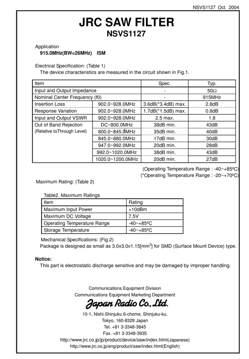
JRC NSVS1127 User manual

JRC

JRC NSVS1127 User manual

Popular Water Filtration System manuals by other brands

Atlantic Ultraviolet Mighty Pure MP16A owner's manual

Atlantic Ultraviolet

Atlantic Ultraviolet Mighty Pure MP16A owner's manual

SunSun CBG-500 Operation manual

SunSun

SunSun CBG-500 Operation manual

Hayward XStream Filtration Series owner's manual

Hayward

Hayward XStream Filtration Series owner's manual

Contech DownSpout StormFilter Operation and maintenance

Contech

Contech DownSpout StormFilter Operation and maintenance

Teka Airfilter MINI operating instructions

Teka

Teka Airfilter MINI operating instructions

Wisy LineAir 100 Installation and operating instructions

Wisy

Wisy LineAir 100 Installation and operating instructions

Schaffner Ecosine FN3446 Series User and installation manual

Schaffner

Schaffner Ecosine FN3446 Series User and installation manual

Pentair FLECK 4600 SXT Installer manual

Pentair

Pentair FLECK 4600 SXT Installer manual

H2O International H20-500 product manual

H2O International

H2O International H20-500 product manual

Renkforce 2306241 operating instructions

Renkforce

Renkforce 2306241 operating instructions

Neo-Pure TL3-A502 manual

Neo-Pure

Neo-Pure TL3-A502 manual

STA-RITE VERTICAL GRID DE FILTERS S7D75 owner's manual

STA-RITE

STA-RITE VERTICAL GRID DE FILTERS S7D75 owner's manual

Applied Membranes W-G844EM Operation and maintenance manual

Applied Membranes

Applied Membranes W-G844EM Operation and maintenance manual

BEGA 116 Instructions for use

BEGA

BEGA 116 Instructions for use

WATA Standard operating instructions

WATA

WATA Standard operating instructions

Price FFU series Installation and service manual

Price

Price FFU series Installation and service manual

Gaggenau BRITA INTENZA 467873 manual

Gaggenau

Gaggenau BRITA INTENZA 467873 manual

Brita SAFF-100 user guide

Brita

Brita SAFF-100 user guide

manuals.online logo
manuals.online logoBrands
  • About & Mission
  • Contact us
  • Privacy Policy
  • Terms and Conditions

Copyright 2025 Manuals.Online. All Rights Reserved.

NSVS778 Apr. 2005
Application
2488.32MHz Data Communications
Electrical Specification: (Table 1)
The device characteristics are measured in the circuit shown in Fig.1.
Maximum Rating: (Table 2)
Mechanical Specifications: (Fig.2)
Package is designed as small as 3.2x2.5x1.1[mm3] for SMD (Surface Mount Device) type.
Notice:
This part is electrostatic discharge sensitive and may be damaged by improper handling.
Table 1. Electrical Specifications (at Room Temperature)
Item Spec. Typ.
Nominal Center Frequency (f0) 2487.92~2488.72MHz 2488.32MHz
Insertion Loss at f0 6.0dB max. 5.0dB
Loaded Q - 1250
Attenuation f0±10MHz 20dB 25dB
Insertion Phase 2488.32MHz - Reference(*1)
Turnover Temperature 37~57ºC 47ºC
Phase Slope - 0.082deg/kHz
Frequency Temperature Coefficient - -0.044ppm/ºC2
Substrate Material - Quartz
*1: Nominal Phase = 0ºType
Table 2. Maximum Ratings
Item Rating
Maximum Input Power 0dBm
Operating Temperature Range -30~+85ºC
Storage Temperature -30~+85ºC
JRC SAW FILTER
NSVS778
Communications Equipment Division
Communications Equipment Marketing Department
10-1, Nishi-Shinjuku 6-chome, Shinjuku-ku,
Tokyo, 160-8328 Japan
Tel. +81 3-3348-3845
Fax. +81 3-3348-3935
http://www.jrc.co.jp/jp/product/device/saw/index.html (Japanese)
http://www.jrc.co.jp/eng/product/saw/index.html(English)
NSVS778 Apr. 2005
1
3
4
5
6
2
(1.35)
(0.8)
(0.55) (0.6) 1.1±0.1
3.2±0.1
2.5±0.1
(1)
(b)
(2)
(a)
[4x]
[4x] [2x]
[2x]
Marking
(1) Lot Number
(a) Year
(b) Month
*Oct.--- X
Nov.--- Y
Dec.--- Z
(2) Part number Mark
Pin no. Connection
1 GND
2 IN/OUT
3 GND
4 GND
5 OUT/IN
6 GND
Fig.1 Measuring circuit
Fig.2 Package dimensions (in mm)
Fig.3 Desirable land area (in mm)
HS
33
12
3
45
6SAW
0.95
0.6
0.95 3.3
1.75 1.75
4.0
1.2
IN
50Ω
OUT
50
Ω
NSVS778 Apr. 2005
Notice
1. Use this component within operating temperature range. It might not be
satisfied with electrical specification without operating temperature range.
When it is used less than –30ºC or more than +85ºC, it might be a cause of
degradation or destruction of the component. Even if it endures during a short
time, it causes degradation of qualification.
2. When soldering iron is used, solder with the temperature at the tip of
soldering iron: 350ºC max., the time of soldering: 10 seconds max., the power
of soldering iron: 30W max..
3. Notice that the allowed time of soldering with soldering iron is accumulated
time, when soldering is repeated.
4. As rapid temperature change for cleaning after reflow soldering might be a
cause of destruction clean this component after confirming that temperature
of this component goes down to room temperature.
5. Confirm that there are not any influence for qualification to this component in
mounting on PCB when this component is cleaned.
6. As it might be a cause of degradation of destruction to apply static electricity
to this component, do not apply static electricity or excessive voltage while
assembling and measuring. And do not transport this component with bare
hand.
Note
1. This specification specifies the quality of this component as a single unit.
Make sure that this component is evaluated and confirmed against this
specification when it is mounted to your products.
2. The information contained herein may be changed without prior notice. It is
therefore advisable to contact Japan Radio Company before proceeding with
the design of equipment incorporating this product.
3. The products are designed to be used with ordinary electronic equipment
(data and communications equipment, office equipment, audio-video
equipment, measuring instruments, etc). Japan Radio Company does not
assume any liability for the case using the products with the application
required high reliability or safety extremely (such as space equipment,
sea-bottom equipment, medical equipment etc). When intending to use any
our product please contact our sales representatives in advance.
CH1: Center 2488.32 Span: 40
0
20
40
60
80
100
Insertion Loss [dB]
Insertion Loss [dB]
CH2: Center 2488.32 Span: 40
0
2
4
6
8
10
CH1: Center 2488.32 Span: 4
0
2
4
6
8
10
Insertion Loss [dB]
Phase [deg]
CH1: Center 2488.32 Span: 4
180
90
0
-90
-180
FREQUENCY CHARACTERISTICS
NSVS778 Apr. 2005
S11 S22
NSVS971 Dec-04
Fig.1 Measuring circuit
13.30±0.20
6.5±0.20
(R0.3)
[4×]
(0.76)
(2.54)
(1.4)
(0.8)
[12×]
(2.54±0.15)
Pin No. Connection
1GND(PKG)
2GND(PKG)
3 GND(PKG)
4GND(PKG)
5OUT/IN
6 GND(signal)
7GND(PKG)
8GND(PKG)
9GND(PKG)
10 GND(PKG)
11 IN/OUT
12 GND(signal)
2.0 max.
(1)
(a) (b)
(3)
Marking
(1) Manufacture's Mark
(2) Lot Number
(a) Year
(b) Month
*Oct.--- X
Nov.--- Y
Dec.--- Z
(c) Date
1-9--- 0
10-19 --- 1
20-31 --- 2
(3) Part Number Mark
(1.26±0.13)
[12×]
[12×]
(2.54)
(R0.3)
(2.54±0.15)
(2)
12345
6
7
8
910
11
12
(C)
Fig.2 Package dimensions(in mm)
J4Y1
VS971
1234
10
987
11
12
6
5
OUT
50O
IN
50O
SAW
*27nH
*27nH
39pF
33pF
*murata LQW18A series