JT Innovations Shift Light Mk2 User manual

Shift Light Unit Mk2
User Guide V2.0
Disclaimer
support@JTi.uk.com
www.JTi.uk.com [email protected]
JT Innovations Ltd
23 Tradecroft Ind. Est.
Wide Street
Portland
Dorset
DT5 2LN
+44 (0) 1305 534535
© JT Innovations Ltd. 2018
Disclaimer
Although every care is taken with the design of this product, JT Innovations Ltd.
can in no way be held responsible for any consequential damage resulting from
the use of this product in your vehicle.
Always operate your vehicle safely and do not allow yourself to be distracted by
your shift light unit while driving.
The shiftlight is intended for Off-Road use only.

Page 2
Contents
Introduction............................................ 3
Shift Light Functions ............................... 3
Installation.............................................. 4
Before You Start ................................. 4
Connectors ......................................... 4
Toucan/Generic .............................. 4
OBD-II ............................................. 4
Tacho .............................................. 5
In-vehicle Mounting............................ 5
Shift Light Configuration via Toucan....... 6
Available Functions......................... 6
Shift Light Configuration via PC .............. 7
Software Installation........................... 7
USB Connection.................................. 7
Configuration –Basics ........................ 8
USB Functions..................................... 9
Shiftlight LED Configuration................ 9
File Functions...................................... 9
CANbus Configuration ...................... 10
Basic Modes.................................. 10
Advanced Modes .......................... 11
Technical............................................... 11
Default CANbus Protocol...................... 12

Page 3
Introduction
Thank you for purchasing a shift light unit. We hope it will be easy to install and configure,
and recommend that you read this guide before you start.
Shift Light Functions
The shift light provides the following functions:
•8 high-brightness RGB LEDs
•Each LED can be set to be yellow, orange, red, green, blue, magenta, cyan or
white.
•Each LED can be set to 1 of 4 different brightness levels
•Each LED has an “on” RPM setting. When the RPM is at or above this value, the
LED will be ON. When below the setting, the LED will be OFF.
•Each LED has an “off” RPM setting. When the RPM is at or above this value the LED
will turn off again. If the value is set very high, the LED will, effectively, not turn off
when the RPM is above its RPM “on” setting
•Each LED can be set to flash or be on constantly when the RPM is above the “on”
value
•A setting allows all LEDs to be turned on with a chosen colour/brightness/flash
mode within a given RPM range
•When used with a Toucan, LEDs can be used to signal an alarm condition
•Configuration can be via Toucan itself, or using a PC programme that can be
downloaded from the JT Innovations website. This uses a standard USB cable
(supplied).
•Tacho mode, allowing connection to a 0-12V tacho pulse
•OBD-II mode, allowing RPM data to be read from vehicles equipped with CANbus
OBD-II ports.

Page 4
Installation
Before You Start
Please check the box contents to ensure nothing is missing. You should have:
Shift Light Unit
Cable Harness
(Toucan, OBD-II or Tacho)
Mounting tape
USB lead
Connectors
Toucan
The cable supplied is intended for direct connection to the expansion socket on the rear of
Toucan. The cable can be connected either way round as the ends are identical.
6 Way connector
Cable Colour
Function
Pin 1
Red
Battery +ve
Pin 2
Black
Ground
Pin 3
Pin 4
Pin 5
White
CAN HI
Pin 6
Yellow
CAN LO
OBD-II
This cable has an OBD-II connector that should be plugged directly in to the OBD-II port of
the vehicle.
The Shiftlight only supports OBD-II ports with CANbus –this includes
most UK/EU vehicles manufactured since 2008.
If in doubt, contact us, or check the OBD-II
connector in the vehicle –for CANbus, pins 6 and
14 must be populated.
It is recommended that you unplug the shiftlight module from the OBD-II
port when it’s not required and the vehicle is turned off – the current draw
is minimal (5mA) but there is a risk that it could drain the battery if the
vehicle is not started for many weeks.

Page 5
Tacho/Generic
This cable has 5 wires
6 Way connector
Cable Colour
Function
Pin 1
Red
Battery +ve
Pin 2
Black
Ground
Pin 3
Pin 4
Green
0-12V tacho drive input
Pin 5
White
CAN HI
Pin 6
Yellow
CAN LO
The Tacho wire should be connected to a suitable source of tacho pulses –these are often
available from a pin on the ECU or instrument cluster.
Do not connect directly to high voltage systems or directly to a distributor or
ignition coil. These signals are at many 100’s of volts and will destroy the
shiftlight module.
Unused wires can be cut off. It is recommended that the cut ends are taped with insulating
tape to prevent short circuits.
In-vehicle Mounting
Two double sided adhesive strips are supplied allowing you to attach the shift light to
anywhere you choose. The dimensions of the unit are such that it will fit neatly on top of
a Toucan touchscreen unit.
Alternatively, there are a pair M2.5 tapped holes on the underside that can be used.
Ensure that the screws do not penetrate too far in to the unit –no more than 5mm.
The mounting hole locations are shown here, with the dimensions in mm.
100
15,4
84
4,5

Page 6
Shift Light Configuration via Toucan
When connected to a Toucan unit the shift light can be configured from Toucan menus.
Toucan firmware V1.50-onwards is required for this. Latest firmware and instructions for
upgrading Toucan are available via the JT Innovations website downloads page.
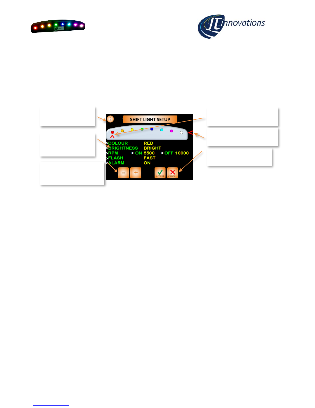
The configuration screen is found under “Settings” from the main screen, then “Setup”,
followed by “Display Setup” and “Shift Light Setup”.
Available Functions
Colour
The colour of each LED can be chosen from: Red, Orange, Yellow, Green, Blue, Magenta, Cyan or White.
In the example above LED 1 is set to RED.
Brightness
Each LED can be set to be: Bright, Medium, Low or Dim. When Toucan is in “night brightness” mode –
which lowers the brightness of the LCD screen –the shift light LEDs will automatically dim. In the
example above, LED1 is set to BRIGHT.
RPM –ON
This is the RPM value that the LED will turn on. In the example above, LED 1 is set to turn on at 5500
rpm.
RPM –OFF
This is the RPM value that the LED will turn off. In the example above, LED 1 is set to turn on at 10,000
rpm. For most engines, this means the LED will not actually turn off once the RPM is above the 5500
“ON” setting.
If you were to set the “off” value to 6000, for example, the LED would only remain on between 5500
and 6000 rpm. This allows the LEDs to chase each other.
Flash
When the RPM values dictate that the LED should be on, this setting determines whether the LED will be
on continuously or whether it will flash.
Alarm
When set “on” the outer two LEDs will flash RED when a Toucan Alarm is triggered.
ALL
This allows a chosen brightness and flash mode to be applied to ALL LEDs for the chosen ON and OFF
RPM.
Touch here for help
Touch parameter to
be changed
Touch here to select the LED
to be configured
Use the +/- buttons to step
through the options for
each parameter.
Touch Accept to keep
changes or Cancel abort.
Touch here to select the “ALL
LEDs” mode to be configured

Page 7
Shift Light Configuration via PC
Software Installation
Visit the JT Innovations download page (www.jti.uk.com/downloads) and click the link for
the configuration software. This will take you to the download page where you can click
“install”. Any necessary Microsoft driver or “.NET” files should also be downloaded.
•Every time the programming software is run, it will automatically check to see
whether there’s a new version available.
USB Connection
The shiftlight has a built-in USB interface using a standard Mini USB cable, supplied with the
unit.
When you plug the shiftlight into a PC or laptop, Windows should auto-detect the
connection and install appropriate drivers.
When you now run the Configuration Software it should automatically detect the shift light
and connect to it. If the main screen shows that the USB connection is disconnected, try
unplugging the USB lead from the computer and then plugging it in again.
•If the program still doesn’t connect, it is possible that there is another device
connected using the same USB device drivers. Try unplugging other USB devices
and, if it still does not connect, contact JT Innovations for technical assistance.

Page 8
Configuration –Basics
A status area on the right of the screen shows the USB connection status and reports the
firmware version of the shift light.

Page 9
USB Functions
Below the USB Connection status area are various buttons related to the shift light that can
be actioned over the USB connection.
•Read. This reads the current configuration of the shift light and shows this in the
application window.
•Send. This sends the configuration displayed in the application window to the shift
light, and instructs the shift light to store the settings in non-volatile memory.
•LEDs on/off. This will instruct the shift light to turn all 8 LEDs on using the values
shown in the application window. Any LEDs set to flash will, however, be on rather
than flashing.
•Run RPM. This simulates the real operation of the shift light by continuously
sending RPM values over the USB connection. This can be started and stopped as
required, and allows you to see how the configured LED settings will appear once
the shift light is back in the vehicle.
•Reset. This resets the RPM run back to the start.
Shiftlight LED Configuration
This area of the application window allows the colour and brightness of each LED to be
configured, as well as whether the LED will flash or not when the RPM settings determine
the LED should be on.
Each LED has an RPM on and RPM off setting –the LED will only be on when the RPM is
above the “on” value and below the “off” value. By setting the “off” value beyond the rpm
range of your engine, the LED will remain on when the RPM is above the “rpm on” value.
“Send” must be clicked before any changes are applied to the shift light.
File Functions
The LED setup as displayed in the application window can be saved to file or loaded from
file. This might be useful if you want different setups for different tracks or weather
conditions, for example.

Page10
CANbus Configuration
Basic Modes
Default
This mode is used when the shift light is to be controlled via Toucan. The CAN protocol used
is documented in a later section so this mode can also be used for custom installations
where you have control over specific CAN shiftlight messages from the ECU (e.g. MoTeC
installations).
Custom
This mode offers a number of preset modes that set the unit up to work directly with
popular after-market ECUs such as Syvecs or AlcaTek. Choose the ECU type from the drop
down box and click “apply”. This applies the CAN bus settings to the application window but
does not send them to the shiftlight.
Tacho
This mode is used when the RPM data from the shiftlight is from a tachi signal (rev counter).
Most tacho signals are actually “ignition pulses per revolution”. This means the setting
would be:
•2 pulses per revolution for a 4 cylinder engine
•3 pulses per revolution for a 6 cylinder engine
•4 pulses per revolution for an 8 cylinder engine
OBD-II
This mode is used when the RPM data is to be read via CANbus from an OBD-II port. When
set to this mode, and the shiftlight is plugged in to an OBD-II port, it will automatically detect
the correct communication method for the vehicle:
•the left hand LED will flash 4 times green every time the unit is powered, and OBD-
II communications are established.
•the left hand LED will flash 4 times red, every 60 seconds, if the unit is powered
but no OBD-II communications are detected –usually when the engine is switched
off.

Page11
Advanced Modes
The CANbus parameters are totally configurable, allowing the unit to be work in virtually any
installation. This requires detailed knowledge of the CAN system you are connecting to, so
reference to ECU documentation will be necessary. We will do our best to assist for custom
installs, so please contact us if needed.
•Data Rate. This can be chosen from 250kbit/s, 500kbit/s or 1Mbit/s.
•CAN Address. This is the address that the RPM data is to be received on.
•RPM MSB Data position. RPM will be received as a 16 bit value, split into two
bytes. This parameter dictates where the shift light will look for the most
significant byte (MSB) of the rpm data.
•RPM LSB Data position. This parameter dictates where the shift light will look for
the least significant byte (LSB) of the rpm data.
•RPM Multiplier and Divider. These two determine how the raw data is
manipulated to derive actual RPM, with the overall divisor shown in the “Resulting
Divisor” field. These are usually left as equal to “1” but may need altering
depending on the vehicle.
•Sequential Message type. This type of CAN bus messaging is where every set of
parameters sent by the ECU has its own unique address. For example RPM data
might be sent on packets with a CAN address of 0x600 whereas vehicle speed
might be sent on a message with a CAN address of 0x610.
•Compound Message type. With this type of message, all data is sent using the
same CAN address (e.g. 0x620) with one of the 8 bytes of data sent having an “ID”
that indicates what the data represents. For this to work two parameters must be
configured:
oCAN ID Position. The byte position where the CAN ID will be found
oCAN ID. The actual ID of the packet containing RPM data.
The configured settings will be displayed in the “CAN structure” diagram at the bottom of
the application window.
Technical
Data Interface
CAN 2.0A/2.0B at 1Mbit/s, 500kbit/s or 250kbit/s. OBD-II compliant
Power
8-20V <20mA typ.
Memory
Non-volatile storage of all parameters
Tacho signal
Grounding pulse or 0-12V pulse stream.
Do not connect directly to high voltage systems.
Do not connect directly to a distributor or ignition coil
Warranty
1 year
Dimensions
100x20x16mm
Weight
30g
LEDs
High Brightness RGB
Package contents
Shift Light unit, power/data cable harness, sticky tape for mounting,
installation guide, USB cable.

Page12
Default CANbus Protocol
As shipped, and when set to “default” mode using the PC software, the following protocol is
used on the CANbus to control the shiftlights:
•Data Rate –1Mbit/s
•11 bit ID
•CAN ID 29 decimal (0x1D hex) for main shift light messages
•Data byte 1 sets LED 1, byte 2 is for LED 2, etc.
•Data values are as follows, in hex:
o0x00 Off
o0x01 Red
o0x20 Orange
o0x40 Yellow
o0x60 Green
o0x80 Blue
o0xA0 Cyan
o0xC0 Magenta
o0xE0 White
•A brightness modifier needs to be added to each of the above values to set the brightness:
o0x1F Full brightness
o0x17 Medium brightness
o0x0F Low brightness
o0x07 Dim brightness
For example:
A full bright red led needs the Hex value 0x01 + 0x1F = 0x20 to be sent.
A medium brightness yellow needs the Hex value 0x40+0x17 = 0x57 to be sent.
•There is also a second message on CAN ID 30 decimal. This is an overall brightness command
that could be used, for example, as a day/night brightness switch. Range is 0-4095 where
4095 is the brightest. The unit will default to full brightness at power up and it is not
necessary to send messages on this ID if not required.
•The unit will time out if it receives no messages after 2 seconds, and turn all LEDs off.
support@JTi.uk.com
www.JTi.uk.com
JT Innovations Ltd
23 Tradecroft Ind. Est.
Wide St.
Portland
Dorset
DT5 2LN
+44 (0) 1305 534 535
Table of contents
Popular Diagnostic Equipment manuals by other brands

Kaixin
Kaixin MSU3 user manual

HC Technologies
HC Technologies OtoSys IM508 manual

Pro-tec
Pro-tec PRS 500 E Instrcutions for use

Pro-tec
Pro-tec 6000CCO Installation and commissioning instructions

Z.I.P.P.ER MASCHINEN
Z.I.P.P.ER MASCHINEN ZI-LP18-AKKU user manual

Gossen MetraWatt
Gossen MetraWatt PROFITEST H+E BASE operating instructions