Graco ProMix Auto Mounting instructions

For use with ProMix Auto and ProControl proportioners.
Important Safety Instructions
Read all warnings and instructions in this
manual. Save these instructions.
311191C
Software Instructions
ProMix Auto™& ProControl™
Network Communications
or
Local
Network
Direct
Local Network
TI7232A

Warnings
2311191C
Contents
Warnings . . . . . . . . . . . . . . . . . . . . . . . . . . . . . . . . . 2
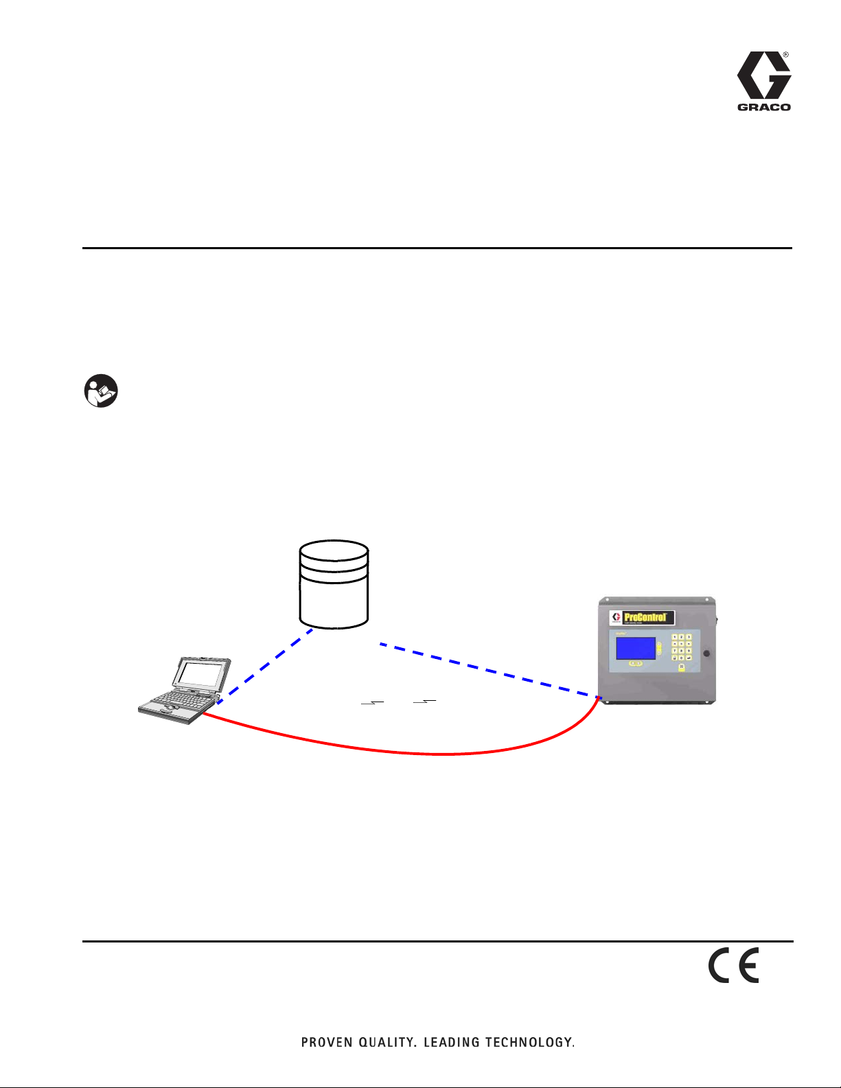
ProMix Network Interfaces . . . . . . . . . . . . . . . . . 3
ProMix Web Interface . . . . . . . . . . . . . . . . . . . . . . . 4
Local Network Connection . . . . . . . . . . . . . . . . . 4
Software Operation . . . . . . . . . . . . . . . . . . . . . . . 7
Web Navigation Screens . . . . . . . . . . . . . . . . . . . 8
Reports . . . . . . . . . . . . . . . . . . . . . . . . . . . . . . . . 9
Modbus/TCP Kit Installation . . . . . . . . . . . . . . . . . 10
ProMix Auto and ProControl Modbus/TCP
Variable Map . . . . . . . . . . . . . . . . . . . . . . . . 12
ProMix Auto Alarms . . . . . . . . . . . . . . . . . . . . . . 17
ProMix Auto Digital Inputs . . . . . . . . . . . . . . . . . 17
ProMix Auto Digital Outputs . . . . . . . . . . . . . . . 17
ProMix Auto Recipe Bits . . . . . . . . . . . . . . . . . . 18
ProMix Auto Color Change Steps . . . . . . . . . . . 19
Parts . . . . . . . . . . . . . . . . . . . . . . . . . . . . . . . . . . . . 20
Kit No. 15G634, Modbus/TCP Converter . . . . . 20
EasyKey Modbus / TCP Wiring Diagram . . . . . . . 21
Graco Standard Warranty . . . . . . . . . . . . . . . . . . . 22
Graco Information . . . . . . . . . . . . . . . . . . . . . . . . . 22
Warnings
The following general warnings are for the setup, use, grounding, maintenance, and repair of this equipment. Addi-
tional, more specific warnings may be found throughout the body of this manual where applicable. Symbols appear-
ing in the body of the manual refer to these general warnings. When these symbols appear throughout the manual,
refer back to these pages for a description of the specific hazard.
WARNING
EQUIPMENT MISUSE HAZARD
Misuse can cause death or serious injury.
•Do not operate the unit when fatigued or under the influence of drugs or alcohol.
•Do not exceed the maximum working pressure or temperature rating of the lowest rated system
component. See Technical Data in all equipment manuals.
•Use fluids and solvents that are compatible with equipment wetted parts. See Technical Data in all
equipment manuals. Read fluid and solvent manufacturer’s warnings. For complete information
about your material, request MSDS forms from distributor or retailer.
•Check equipment daily. Repair or replace worn or damaged parts immediately with genuine Graco
replacement parts only.
•Do not alter or modify equipment.
•Use equipment only for its intended purpose. Call your Graco distributor for information.
•Route hoses and cables away from traffic areas, sharp edges, moving parts, and hot surfaces.
•Do not kink or over bend hoses or use hoses to pull equipment.
•Keep children and animals away from work area.
•Comply with all applicable safety regulations.
ELECTRIC SHOCK HAZARD
Improper grounding, setup, or usage of the system can cause electric shock.
•Turn off and disconnect power at main switch before disconnecting any cables and before servicing
equipment.
•Connect only to grounded power source.
•All electrical wiring must be done by a qualified electrician and comply with all local codes and
regulations.

Warnings
311191C 3
This manual (311191) is available in the following languages:
ProMix Network Interfaces
Web and Modbus Interface
Web Interface - allows users to connect, view, and
change the ProMix setup, log, and error files. It does not
display run data.
Modbus/TCP - enables process equipment to read vari-
ables while operating, as well as control the machine
and change setup. It does not provide access to job and
error logs.
Use the ProMix Software to:
•Update software
•View
➜software versions
➜material usage report
•Upload
➜setup values
➜a custom language to view on screen
•Download
➜setup values
➜job and alarm logs
•Clear
➜job and alarm logs
➜material usage report
•Reset
➜factory defaults
➜password
If Java Error appears when running the program
for the first time, you must download Java RTE (Run
Time Environment) for the program to operate correctly.
Follow the screen link to Java version 1.4.2.09 or newer.
Or enter http://java.sun.com/j2se/1.4.2/download.html
and select Download J2SE JRE. The file is approxi-
mately 15 MB.
Manual Language Manual Language
311191 English 311277 Chinese
311273 French 311278 Korean
311274 Spanish 311297 Italian
311318 German 311298 Dutch
311276 Japanese
✓If the Graco program will not start, check the
following.
Is the ProMix power on?
Are the cables fully seated in both the PC and
ProMix ports?
•Is the LED on the EasyKey™illuminated?
•Is the LED on the ethernet jack illuminated?
Are the LEDs on the back of the EasyKey
illuminated? The bottom left LED should be
constantly illuminated showing a network
connection. The bottom right LED should
illuminate when network traffic is occurring.
If there are no LEDs illuminated check for
loose connections or a loose board.
To isolate the problem, try communicating with a
different:
•PC
•ProMix system if available
Check Local Network Connection. See page 4.

ProMix Web Interface
4311191C
ProMix Web Interface
There are two possible ways to connect a PC to the Pro-
Mix Auto or ProControl.
•Local Network Connection (most common). Patch
cable from the local network plugs into the ProMix
Web Interface connection. See FIG. 1 and Local
Network Connection, below.
•Direct Connection to the ProMix Auto or ProCon-
trol. Crossover cable from the PC plugs into the Pro-
Mix Web Interface connection. (A crossover cable is
provided with all systems.) See FIG. 1 and page 10.
Local Network Connection
Hardware and Software Configuration
Hardware
Patch cables are used to connect each ProMix unit to
the local network and to the ProMix Web connection (A)
on the EasyKey panel. See FIG. 2.
FIG. 1 Network Selection
Laptop PC
Non-hazardous Area Only
EasyKey Display
Patch Cable
or
Patch Cable
Local
Network
Direct Connection
Crossover Cable
Local Network Connection
TI7232A
FIG. 2 EasyKey Web Connection
A
Modbus2

ProMix Web Interface
311191C 5
Microsoft Browser Configuration
1. Before running the web interface software you must
manually assign an IP address to your computer:
a. On your computer, click on the Start button
to open the menu, then click
on Control Panel .
b. See FIG. 3. Double click on Network Connec-
tions. Double click on Local Area Connection to
open the Local Area Connection Status window.
Click on Properties to open the Local Area Con-
nection Properties window. See FIG. 4.
FIG. 3. Assign IP Address on Computer

ProMix Web Interface
6311191C
c. In the Local Area Connection Properties win-
dow, scroll to Internet Protocol (TCP/IP) and
double click, to open the Internet Protocol
(TCP/IP) Properties window. See FIG. 5.
d. See FIG. 5. Set to “Use the following IP
address:”
e. Type in the following IP address:
192.168.0.3
f. Type in the following Subnet mask:
255.255.255.0
g. Click on OK to accept the change and close the
Internet Protocol (TCP/IP) Properties window.
h. Click on OK to close the Local Area Connection
Properties window.
i. Close the Local Area Connection Properties
window and Network Connections window.
2. On the EasyKey, go to Advanced Screen 4 and
write down the IP number assigned to that EasyKey
(1-99).
FIG. 4: Local Area Connection Properties Window
FIG. 5: Internet Protocol (TCP/IP) Window
192 . 168 . 0 . 3

ProMix Web Interface
311191C 7
3. The ProMix EasyKey software requires Sun Java to
operate. Open your web browser options and select
Java (Sun) and deselect the Microsoft VM selection.
See FIG. 6. If the Sun Java option is not available fol-
low the Software Operation procedure and load
the Sun Java program when the appropriate screen
and link appear.
Browser must be closed and restarted for change
to be effective.
It may be necessary to change the Java selection
from Sun to Microsoft for other software applications to
run correctly on your PC.
If you cannot make these changes contact your I.S.
department and request they change your computer
access rights. You must have administrative rights to
change the settings.
Software Operation
1. Open Microsoft Internet Explorer.
2. In the address area type http://192.168.0.1
3. Click Enter.
4. Select yes when security screen appears.
5. Main software screen appears. See FIG. 7.
•If “Cannot Read Firmware” appears check for
loose hardware connections.
•If “Java script needs to be loaded” appears fol-
low the screen link to install this freeware.
FIG. 6 Java Internet Options
Use smooth scrolling
HTTP 1.1 settings
Use HTTP 1.1
Use HTTP 1.1 through proxy connections
Java (Sun)
Use Java 2 v1.4.2_09 for <applet> (requires restart)
Microsoft VM
Java console enabled (requires restart)
Java logging enabled
JIT compiler for virtual machine enabled (requires restart)
FIG. 7 Main Software Screen
Reports
Display setup values
Restore setup values
Setup
Download setup values
Install EasyKey
TM
software
Restore custom language
Download custom language
End current job
Reset password
Reset settings
Software Resets
Display material usage report
Clear material usage report
Download job log
Download error log
Display job log
Display error log
Clear job log
Clear error log
Version 2.00.009

ProMix Web Interface
8311191C
Web Navigation Screens
From the main screen (see FIG. 7) the operator can
select Setup, Reports, or Software Resets.
Setup
Download setup values - saves the ProMix
configuration to the PC. This file can be opened and
edited using Microsoft Excel, or used to set up multiple
systems.
Restore setup values - allows files to be uploaded and
restored to the ProMix.
Display setup values - indicates what values are
currently being used for the system. Allows the operator
to verify that the right values are being used. See FIG. 8.
Download custom language - saves the current
system language to the PC. This file is opened and a
custom language added to the B column of the Excel
file. See FIG. 9.
Custom languages are limited to Ascii and Ascii
extended characters and a maximum of 32 characters.
Save the Excel file as a tab delineated file for uploading
purposes.
Restore custom language - allows the custom lan-
guage file to be uploaded to the ProMix.
End current job - ends a job and adds material to
usage report.
Software Resets
Install EasyKey software - downloads the Graco
provided software to the PC (approximately 5 minutes).
Once complete the control panel will be reprogrammed
from the EasyKey.
Reset settings - places system back to factory default
mode.
Reset password - clears password if lost or forgotten.
Advanced Configuration
To change IP settings, type in 192.168.0.1\config.html.
Or use the freeware configuration program available
from www.lantronix.com/device-networking/utili-
ties-tools/device-installer.html.
FIG. 8 Display Set up
Data for Display setup values
TargetRatio0 10
TargetRatio1 10
TargetRatio2 10
TargetRatio3 10
TargetRatio4 10
TargetRatio5 10
TargetRatio6 10
TargetRatio7 10
FIG. 9 Download Custom Language
Save In bin
File Name:
Files of Type:
Download custom language
Combined_2_00_006.REC
vssver.scc
All Files
Combined_2_00_007.rec vssver.scc
DisplayBoard_2_00
_
Combined_2_00_008.rec
DisplayBoard_2_00_004.rec
DisplayBoard_2_00_005.rec
DisplayBoard_2_00_006.rec
DisplayBoard_2_00_007.rec

ProMix Web Interface
311191C 9
Reports
Display material usage report - shows the material
sprayed from the ProMix. See FIG. 10.
Clear material usage report - deletes the material
usage from the display.
Download job log - downloads the job log to the PC.
Download error log - downloads the error log to the
PC.
Display jog log - displays the job number, date, time,
recipe, ratio, target, volumes, grand totals, and any
errors that occurred during the job. See FIG. 11.
Display error log - displays the number of alarms, date,
time, recipe and what the error was. See FIG. 12.
Clear job log - deletes the jobs from the display.
Clear error log - deletes the errors from the display.
FIG. 10 Display Material Usage report
Data for Display material usage report
Start Time
09-23-2005
Material Usage
End Time
Recipe
1
2
3
09-22-2005
0
A (cc)
0
00
0
0
B (cc)
10:22:15
16:33:57
FIG. 11 Display Job Log
FIG. 12 Display Error Log
Data for Display job log
Job
001
002
003
004
005
Date
23-Sep-2005
23-Sep-2005
23-Sep-2005
23-Sep-2005
23-Sep-2005
Time
10:21:16
10:21:19
10:21:20
10:21:21
10:21:21
Recipe
1
1
1
1
1
Ratio
0.00
0.00
0.00
0.00
0.00
Target
1.0
1.0
1.0
1.0
1.0
Vol A
0
0
0
0
0
Data for display error log
Alarm
001
002
003
Date
23-Sep-2005
23-Sep-2005
23-Sep-2005
Time
10:16:06
10:14:44
10:14:44
Recipe
0
32
32
Error
E1
E17
E18
Communication Error
Power On
Factory Defaults Restored

Modbus/TCP Kit Installation
10 311191C
Modbus/TCP Kit Installation
Graco Kit 15G634 is required for this connection.
Communication delays between the ProMix and
Robot can be adjusted. Call Graco Customer Service for
instructions.
Kit Installation
1. Turn ProMix Auto or ProControl power off and dis-
connect power source.
2. Open the EasyKey enclosure with its key.
3. Knock out the prepared hole (B) from the bottom of
the EasyKey enclosure. See FIG. 13.
4. Install bulkhead ethernet connector (2) in bottom of
enclosure. See FIG. 14.
5. Loosen existing DIN rail end blocks (C) and spread
apart.
6. Install the Modbus/TCP converter (1) next to the
power supply (PS).
7. Position DIN rail end blocks (C) against the Mod-
bus/TCP converter (1) and power supply (PS) to
prevent them from moving.
Cable Connections
(FIG. 14 shows a completed Modbus/TCP Kit
Installation).
1. Connect the 24-volt power supply with wire mod-
bus/TCP harness (5).
2. Install second part of harness to J11 on display
board to complete communications circuit. Connect
loose end to the top of the converter module. See
“EasyKey Modbus / TCP Wiring Diagram” on
page 21.
Do not operate ProMix Auto or ProControl with equip-
ment enclosure doors/covers open. Disconnect power
source before servicing or electrically wiring. See
Warnings on page 2.
FIG. 13 EasyKey Modbus/TCP Connection
B
Modbus2

Modbus/TCP Kit Installation
311191C 11
3. Connect green ground wire from the converter to
the ground bus bar (G).
4. Route the Modbus/TCP wire harness (5) through
two wire tie pads (9) to maintain clearance from the
IS circuit (IS).
5. Install modular RJ45 cable (3) between converter
and bulkhead. Be sure to plug cable into correct
plug on converter module. See location in FIG.
14.
6. Close and lock the EasyKey door.
Make sure the red switch on the front is set to
RS-485.
Changing Network Configuration
1. Connect PC to ethernet connection on EasyKey
with the crossover cable.
2. Connect network to PC with DeviceInstaller.
3. Run DeviceInstaller program.
A freeware configuration program is available
from www.lantronix.com/device-networking/utili-
ties-tools/device-installer.html
4. Change IP Address from Default setting 192.168.02
a. Run DeviceInstaller
b. Click “Search”
c. Select device
d. Click “Assign IP”
Select and assign specific IP address.
i. Input address
ii. Enter subnet mask 255.255.255.0
iii. Click “Assign” (unit is programmed and will
now reboot)
iv. Click “Finish”
v. Close/Exit DeviceInstaller
Alternate method via telnet and port 9999.
Serial Port Setup
Kit is pre-programmed with these settings.
- Modbus Slave
- RTU format
- RS-485, 2-wire
- 57,600 baud, 8-bit, no parity, 1-stop bit.
FIG. 14 Cable Connections
1
3C
5G
Install bulkhead connector (2)
in bottom of enclosure
PS
9
9
IS

Modbus/TCP Kit Installation
12 311191C
ProMix Auto and ProControl Modbus/TCP Variable Map
Run Variables
Address Variable Name Size Min. Max. Notes Read
Only
40003 FlowRate 16 bits 0 5000 Value is CC/min (0-1200) Y
40004 ActualRatio 16 bits 0 9999 10 = 1.0 ratio with decimal Y
40005 ActiveRecipe 16 bits 0 60 Recipe Number Y
40006 ActiveFault 32 bits 0 0xFFFF_FFFF 32-bit, 1-bit per Alarm - see detailed table
40008 PotlifeRemaining 16 bits 0 9999 Time in minutes Y
40009 JobComplete 16 bits 1 4 JOBCOMPLETE=1, JOBPURGE=2, JOBCC=3,
JOBCCDONE=4
Y
40010 JobTotal0 32 bits 0 799,999,999 Total for Meter A in CCs Y
40012 JobTotal1 32 bits 0 799,999,999 Total for Meter B in CCs Y
40014 JobTotal2 32 bits 0 799,999,999 Total for Flow Control Only Inline Meter in CCs Y
40016 GrandTotal 32 bits 0 799,999,999 Grand Total in Liters Y
40018 ControlVer 32 bits 0 0xFFFF_FFFF Software Version for fluid plate control board Y
40020 RobotDigitalIn 16 bits 0 0xFFFF 1-bit for each input, Set/clear for actions - next
detailed table
40021 RobotDigitalOut 16 bits 0 0xFFFF 1-bit for each input, Set/clear for actions - next
detailed table Y
40022 Component 16 bits 0 2 Active Component (shown on run screen) Y
40023 SetupOpen 16 bits 0 1 1 if in setup screens -> 0 Run Screens Y
40026 ccNewRecipe 16 bits 0 60 New recipe when RobotDigitalIn recipe bits are
changed
Y
40027 Opmode 16 bits 0 99 0=MIX 1=PURGE 2=STANDBY 3=COLOR-
CHANGE 4=CC_MIX 5=CC_PURGE 6=METER-
CAL 7=FLOWCAL 8=AUTODUMP
40029 DesFlow 16 bits 0 9999 Flow Command Input (Analog)
Setup Variables
Address Variable Name Size Min. Max. Notes Read
Only
41002 TargetRatio0 16 bits 0 300 300 = 30.0 with decimal
41062 TargetRatio60 16 bits 0 300
41063 Tolerance0 16 bits 1 99 Percentage 1-99%
41123 Tolerance60 16 bits 1 99
41124 PotlifeTime0 16 bits 0 999 Minutes
41184 PotlifeTime60 16 bits 0 999
41185 PurgeTime0 16 bits 0 99 Seconds
41245 PurgeTime60 16 bits 0 99
41246 FillTime0 16 bits 0 99 Seconds
41306 FillTime60 16 bits 0 99
41307 SolventFillTime 16 bits 0 999 Seconds
41368 Color0 16 bits 1 30 Color Valve for Recipe 0
41428 Color60 16 bits 1 30 Color Valve for Recipe 60
41429 Catalyst0 16 bits 1 30 Catalyst Valve for Recipe 0
41489 Catalyst60 16 bits 1 30 Catalyst Valve for Recipe 60
41490 KFact0 16 bits 1 999 K-factor for Meter A
41491 KFact1 16 bits 1 999 K-factor for Meter B
41492 KFact2 16 bits 1 999 K-factor for Flow Control Only inline meter
41493 CalVolume0 16 bits 0 999 Calibration Volume Entered on screen for Meter A Y

Modbus/TCP Kit Installation
311191C 13
41494 CalVolume1 16 bits 0 999 Calibration Volume Entered on screen for Meter B Y
41495 CalVolume2 16 bits 0 999 Calibration Volume Entered on screen for inline
Meter
Y
41496 Calibration 16 bits 0 8 Used during calibration steps and drop-down win-
dow
0=Abort, 1=Start_A, 2=Start_B, 3=Start_FC,
4=Active, 5=Complete, 6=Purge, 7=Cal_Start,
8=Cal_Complete
Y
41497 Language 16 bits 0 9 0=English, 1=Spanish, 2=French, 3=German,
4=Italian, 5=Dutch, 6=Japanese, 7=Chinese,
8=Korean, 9=Custom
41498 DisplayUnits 16 bits 0 1 0=Metric (cc/L), 1=US (oz/Gal)
41499 Kp 16 bits 0 9999 Proportional Gain
41500 Ki 16 bits 0 9999 Integral Gain
41501 PotlifeVolume 16 bits 0 999 CCs
41502 AirChopTime 16 bits 0 999 Seconds
41503 SolventChopTime 16 bits 0 999 Seconds
41504 ColorDumpTime 16 bits 0 999 Seconds
41505 ColorFillTime 16 bits 0 999 Seconds
41506 Password 32 bits 0 9999 1=Lock setup screens on display
41508 DoseSize 16 bits 0 3 0=15cc, 1=25cc, 2=50cc
41509 StationNum 16 bits 1 245 Modbus Address for slave port
41510 FlowControlMeter 16 bits 0 1 0=Flow Single Meter, 1=Flow with Proportioning Y
41511 FlowControl 16 bits 0 2 0=Prop Only, 1=Flow Only, 2=Prop+Flow Control
41514 FlowTolerance 16 bits 0 50 0-50%
41515 FlowSetpoint 16 bits 0 1200 Manual Scaled Flow Command Signal Y
41516 FlowSetpoint-
Source
16 bits 0 2 0=Analog, 1=Network, 2=Manual
41517 ThirdFlushValve 16 bits 0 1 0=OFF, 1=ON
41526 CommandFullS-
cale
16 bits 0 2 0 = 0-300, 1 = 0-600, 2 = 0-1200
41528 ThirdFlushFirst-
PurgeTime
16 bits 0 999 Seconds
41529 ColorBoards 0xFFFF 0x0000=0 catalyst boards and 0 color boards
0x0010=1 catalyst boards and 0 color boards
0x0001=0 catalyst boards and 1 color boards
0x0011=1 catalyst boards and 1 color boards
0x0003=0 catalyst boards and 2 color boards
0x0013=1 catalyst boards and 2 color boards
0x0007=0 catalyst boards and 3 color boards
0x0017=1 catalyst boards and 3 color boards
0x000F=0 catalyst boards and 4 color boards

Modbus/TCP Kit Installation
14 311191C
Miscellaneous Variables
Address Variable Name Size Min. Max. Notes Read
Only
42003 Month 16 bits 1 12 Y
42004 Day 16 bits 1 31 Y
42005 Year 16 bits 2003 2999 Y
42006 Hour 16 bits 0 23 Y
42007 Minute 16 bits 0 59 Y
42008 Second 16 bits 0 59 Y
42009 ScreenTimeout 16 bits 0 99 Minutes - 0 is disabled
42025 JobAlarm 16 bits 0 65535 Each bit is set if an Alarm occurs any time during
this job
Y
42028 DateFormat 16 bits 0 1 dd/mm/year = 1, mm/dd/year = 0
42029 MatUseStart-
Date
32 bits 0 65535 Byte0 = Day, Byte1 = Month, Byte2 = Year Y
42031 MatUseStart-
Time
32 bits 0 65535 Byte0 = Second, Byte1 = Minutes, Byte2 = Hour Y
42033 TotalA0 32 bits 0 0xFFFF_FFFF Total for Recipe 0, A material, CCs Y
42035 TotalA1 32 bits 0 0xFFFF_FFFF Y
42037 TotalA2 32 bits 0 0xFFFF_FFFF Y
42039 TotalA3 32 bits 0 0xFFFF_FFFF Y
42041 TotalA4 32 bits 0 0xFFFF_FFFF Y
42043 TotalA5 32 bits 0 0xFFFF_FFFF Y
42045 TotalA6 32 bits 0 0xFFFF_FFFF Y
42047 TotalA7 32 bits 0 0xFFFF_FFFF Y
42049 TotalA8 32 bits 0 0xFFFF_FFFF Y
42051 TotalA9 32 bits 0 0xFFFF_FFFF Y
42053 TotalA10 32 bits 0 0xFFFF_FFFF Y
42055 TotalA11 32 bits 0 0xFFFF_FFFF Y
42057 TotalA12 32 bits 0 0xFFFF_FFFF Y
42059 TotalA13 32 bits 0 0xFFFF_FFFF Y
42061 TotalA14 32 bits 0 0xFFFF_FFFF Y
42063 TotalA15 32 bits 0 0xFFFF_FFFF Y
42065 TotalA16 32 bits 0 0xFFFF_FFFF Y
42067 TotalA17 32 bits 0 0xFFFF_FFFF Y
42069 TotalA18 32 bits 0 0xFFFF_FFFF Y
42071 TotalA19 32 bits 0 0xFFFF_FFFF Y
42073 TotalA20 32 bits 0 0xFFFF_FFFF Y
42075 TotalA21 32 bits 0 0xFFFF_FFFF Y
42077 TotalA22 32 bits 0 0xFFFF_FFFF Y
42079 TotalA23 32 bits 0 0xFFFF_FFFF Y
42081 TotalA24 32 bits 0 0xFFFF_FFFF Y
42083 TotalA25 32 bits 0 0xFFFF_FFFF Y
42085 TotalA26 32 bits 0 0xFFFF_FFFF Y
42087 TotalA27 32 bits 0 0xFFFF_FFFF Y
42089 TotalA28 32 bits 0 0xFFFF_FFFF Y
42091 TotalA29 32 bits 0 0xFFFF_FFFF Y
42093 TotalA30 32 bits 0 0xFFFF_FFFF Y
42095 TotalA31 32 bits 0 0xFFFF_FFFF Y
42097 TotalA32 32 bits 0 0xFFFF_FFFF Y
42099 TotalA33 32 bits 0 0xFFFF_FFFF Y

Modbus/TCP Kit Installation
311191C 15
42101 TotalA34 32 bits 0 0xFFFF_FFFF Y
42103 TotalA35 32 bits 0 0xFFFF_FFFF Y
42105 TotalA36 32 bits 0 0xFFFF_FFFF Y
42107 TotalA37 32 bits 0 0xFFFF_FFFF Y
42109 TotalA38 32 bits 0 0xFFFF_FFFF Y
42111 TotalA39 32 bits 0 0xFFFF_FFFF Y
42113 TotalA40 32 bits 0 0xFFFF_FFFF Y
42115 TotalA41 32 bits 0 0xFFFF_FFFF Y
42117 TotalA42 32 bits 0 0xFFFF_FFFF Y
42119 TotalA43 32 bits 0 0xFFFF_FFFF Y
42121 TotalA44 32 bits 0 0xFFFF_FFFF Y
42123 TotalA45 32 bits 0 0xFFFF_FFFF Y
42125 TotalA46 32 bits 0 0xFFFF_FFFF Y
42127 TotalA47 32 bits 0 0xFFFF_FFFF Y
42129 TotalA48 32 bits 0 0xFFFF_FFFF Y
42131 TotalA49 32 bits 0 0xFFFF_FFFF Y
42133 TotalA50 32 bits 0 0xFFFF_FFFF Y
42135 TotalA51 32 bits 0 0xFFFF_FFFF Y
42137 TotalA52 32 bits 0 0xFFFF_FFFF Y
42139 TotalA53 32 bits 0 0xFFFF_FFFF Y
42141 TotalA54 32 bits 0 0xFFFF_FFFF Y
42143 TotalA55 32 bits 0 0xFFFF_FFFF Y
42145 TotalA56 32 bits 0 0xFFFF_FFFF Y
42147 TotalA57 32 bits 0 0xFFFF_FFFF Y
42149 TotalA58 32 bits 0 0xFFFF_FFFF Y
42151 TotalA59 32 bits 0 0xFFFF_FFFF Y
42153 TotalA60 32 bits 0 0xFFFF_FFFF Total for Recipe 60, A material, CCs Y
42155 TotalB0 32 bits 0 0xFFFF_FFFF Total for Recipe 0, B material, CCs Y
42157 TotalB1 32 bits 0 0xFFFF_FFFF Y
42159 TotalB2 32 bits 0 0xFFFF_FFFF Y
42161 TotalB3 32 bits 0 0xFFFF_FFFF Y
42163 TotalB4 32 bits 0 0xFFFF_FFFF Y
42165 TotalB5 32 bits 0 0xFFFF_FFFF Y
42167 TotalB6 32 bits 0 0xFFFF_FFFF Y
42169 TotalB7 32 bits 0 0xFFFF_FFFF Y
42171 TotalB8 32 bits 0 0xFFFF_FFFF Y
42173 TotalB9 32 bits 0 0xFFFF_FFFF Y
42175 TotalB10 32 bits 0 0xFFFF_FFFF Y
42177 TotalB11 32 bits 0 0xFFFF_FFFF Y
42179 TotalB12 32 bits 0 0xFFFF_FFFF Y
42181 TotalB13 32 bits 0 0xFFFF_FFFF Y
42183 TotalB14 32 bits 0 0xFFFF_FFFF Y
42185 TotalB15 32 bits 0 0xFFFF_FFFF Y
42187 TotalB16 32 bits 0 0xFFFF_FFFF Y
42189 TotalB17 32 bits 0 0xFFFF_FFFF Y
42191 TotalB18 32 bits 0 0xFFFF_FFFF Y
42193 TotalB19 32 bits 0 0xFFFF_FFFF Y
42195 TotalB20 32 bits 0 0xFFFF_FFFF Y
42197 TotalB21 32 bits 0 0xFFFF_FFFF Y
42199 TotalB22 32 bits 0 0xFFFF_FFFF Y
42201 TotalB23 32 bits 0 0xFFFF_FFFF Y

Modbus/TCP Kit Installation
16 311191C
42203 TotalB24 32 bits 0 0xFFFF_FFFF Y
42205 TotalB25 32 bits 0 0xFFFF_FFFF Y
42207 TotalB26 32 bits 0 0xFFFF_FFFF Y
42209 TotalB27 32 bits 0 0xFFFF_FFFF Y
42211 TotalB28 32 bits 0 0xFFFF_FFFF Y
42213 TotalB29 32 bits 0 0xFFFF_FFFF Y
42215 TotalB30 32 bits 0 0xFFFF_FFFF Y
42217 TotalB31 32 bits 0 0xFFFF_FFFF Y
42219 TotalB32 32 bits 0 0xFFFF_FFFF Y
42221 TotalB33 32 bits 0 0xFFFF_FFFF Y
42223 TotalB34 32 bits 0 0xFFFF_FFFF Y
42225 TotalB35 32 bits 0 0xFFFF_FFFF Y
42227 TotalB36 32 bits 0 0xFFFF_FFFF Y
42229 TotalB37 32 bits 0 0xFFFF_FFFF Y
42231 TotalB38 32 bits 0 0xFFFF_FFFF Y
42233 TotalB39 32 bits 0 0xFFFF_FFFF Y
42235 TotalB40 32 bits 0 0xFFFF_FFFF Y
42237 TotalB41 32 bits 0 0xFFFF_FFFF Y
42239 TotalB42 32 bits 0 0xFFFF_FFFF Y
42241 TotalB43 32 bits 0 0xFFFF_FFFF Y
42243 TotalB44 32 bits 0 0xFFFF_FFFF Y
42245 TotalB45 32 bits 0 0xFFFF_FFFF Y
42247 TotalB46 32 bits 0 0xFFFF_FFFF Y
42249 TotalB47 32 bits 0 0xFFFF_FFFF Y
42251 TotalB48 32 bits 0 0xFFFF_FFFF Y
42253 TotalB49 32 bits 0 0xFFFF_FFFF Y
42255 TotalB50 32 bits 0 0xFFFF_FFFF Y
42257 TotalB51 32 bits 0 0xFFFF_FFFF Y
42259 TotalB52 32 bits 0 0xFFFF_FFFF Y
42261 TotalB53 32 bits 0 0xFFFF_FFFF Y
42263 TotalB54 32 bits 0 0xFFFF_FFFF Y
42265 TotalB55 32 bits 0 0xFFFF_FFFF Y
42267 TotalB56 32 bits 0 0xFFFF_FFFF Y
42269 TotalB57 32 bits 0 0xFFFF_FFFF Y
42271 TotalB58 32 bits 0 0xFFFF_FFFF Y
42273 TotalB59 32 bits 0 0xFFFF_FFFF Y
42275 TotalB60 32 bits 0 0xFFFF_FFFF Total for Recipe 60, B material, CCs Y

Modbus/TCP Kit Installation
311191C 17
ProMix Auto Alarms
ProMix Auto Digital Inputs
ProMix Auto Digital Outputs
Bit Active Fault Binary Name Alarm / Warning
0 0000_0000_0000_0001 Communications Alarm
1 0000_0000_0000_0010 Potlife Alarm
2 0000_0000_0000_0100 Ratio High Alarm
3 0000_0000_0000_1000 Ratio Low Alarm
4 0000_0000_0001_0000 Overdose A Alarm
5 0000_0000_0010_0000 Overdose B Alarm
6 0000_0000_0100_0000 Dose Time A Alarm
7 0000_0000_1000_0000 Dose Time B Alarm
8 0000_0001_0000_0000 Mix in Setup Alarm
9 0000_0010_0000_0000 Remote Stop Alarm
10 0000_0100_0000_0000 Purge Volume Alarm
11 0000_1000_0000_0000 Color Change Communications Alarm
12 0001_0000_0000_0000 High Flow Rate Warning
13 0010_0000_0000_0000 Low Flow Rate Warning
14 0100_0000_0000_0000 System Idle Warning
Bit RobotDigitalIn Binary Name Details
0 0000_0000_0000_0001 Mix Start Set bit active "1" to initiate or start mixing material
1 0000_0000_0000_0010 Purge Start Set bit active "1" to initiate or start purging material, mix must be inac-
tive
2 0000_0000_0000_0100 Color Change
Start
Set bit active "1" to initiate or start color change, both mix and purge
must be inactive
8:3 0000_000X_XXXX_X000 Recipe Bits (6) Set bit to select recipe. See next sheet.
9 0000_0010_0000_0000 Gun Trigger Set bit active "1" when gun is triggered. Used by software for various
actions.
10 0000_0100_0000_0000 Job Complete Set bit active "1" to complete the current job. Job totals are cleared and
added to material usage
11 0000_1000_0000_0000 Remote Stop Set bit active "1" to stop system and place in standby mode (must clear
alarm first)
12 0001_0000_0000_0000 Alarm Reset Set bit active "1" to clear current alarm.
Bit RobotDigitalOut Binary Name Details
0 0000_0000_0000_0001 Purge_CC_Active "1" when a purge or color change is in progress
1 0000_0000_0000_0010 Mix_Active "1" when mix is active
2 0000_0000_0000_0100 Mix_Ready "1" when color change is complete and ready for mixing
3 0000_0000_0000_1000 Alarm "1" when an Alarm occurred
4 0000_0000_0001_0000 Warning "1" when a Warning occurred

Modbus/TCP Kit Installation
18 311191C
ProMix Auto Recipe Bits
Recipe Bits Number Recipe Bits Number
543210 543210
000000 0 100001 33
000001 1 100010 34
000010 2 100011 35
000011 3 100100 36
000100 4 100101 37
000101 5 100110 38
000110 6 100111 39
000111 7 101000 40
001000 8 101001 41
001001 9 101010 42
001010 10 101011 43
001011 11 101100 44
001100 12 101101 45
001101 13 101110 46
001110 14 101111 47
001111 15 110000 48
010000 16 110001 49
010001 17 110010 50
010010 18 110011 51
010011 19 110100 52
010100 20 110101 53
010101 21 110110 54
010110 22 110111 55
010111 23 111000 56
011000 24 111001 57
011001 25 111010 58
011010 26 111011 59
011011 27 111100 60
011100 28
011101 29
011110 30
011111 31
100000 32

Modbus/TCP Kit Installation
311191C 19
ProMix Auto Color Change Steps
Action Description
Clear MIX bit Clear mix bit to place system in standby
wait 100ms
Wait for MIX_ACTIVE off Wait for system to complete request
wait 100ms
Set recipe bits Set the recipe bits for the next color
wait 100ms
Set Color Change Start Set color change bit to initiate start of color change
wait 100ms
Check for Purge/CC Active Check if status output indicate the change
wait 100ms
Wait for Mix Ready active Wait for completion of the color change

Parts
20 311191C
Parts
Kit No. 15G634, Modbus/TCP Converter
3
1
5
Install bulkhead connector (2)
in bottom of enclosure
9
9
Ref.
No. Part No. Description Qty
1 120090 CONVERTER, modbus/TCP 1
2 198165 KIT, accessory RJ45 Jack/Bulkhead 1
3 117162 CABLE, modular RJ45, 3ft 1
5 15G635 HARNESS, wire, modbus/TCP 1
9 n/a HOLDER, wire tie 2
Other manuals for ProMix Auto
2
This manual suits for next models
1
Table of contents
Other Graco Conference System manuals