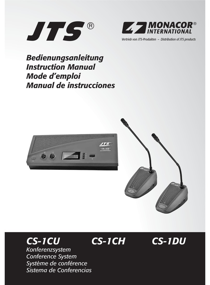
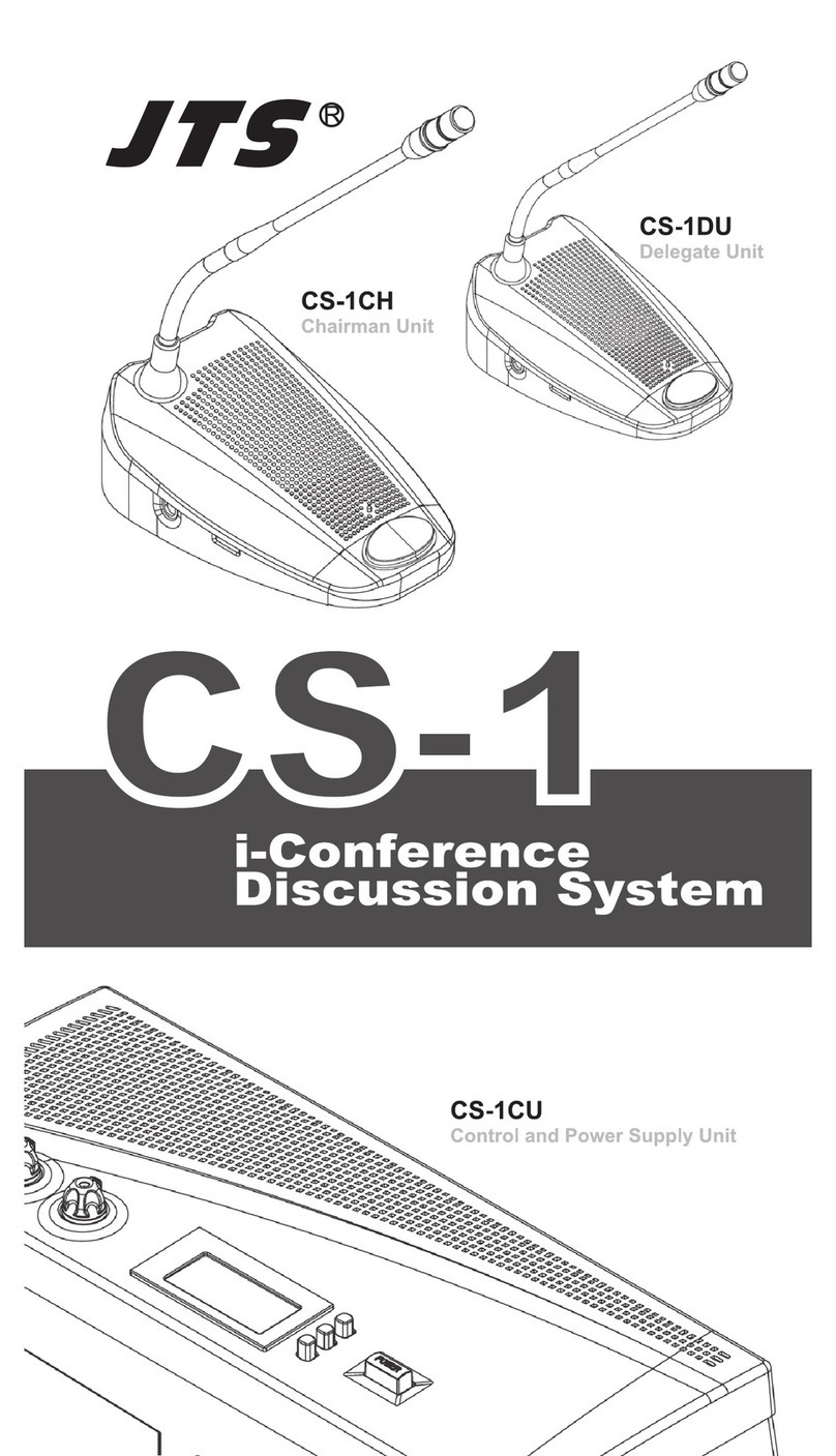
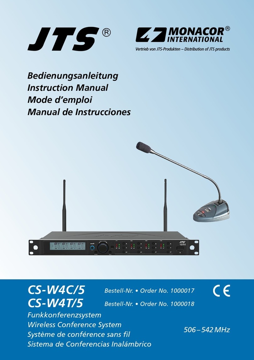
JTS CS-W4C User manual

59508-114-01
PROFESSIONAL CO., LTD.
No. 148, 9th Industry Road, Ta-Li Industrial Park,
Taichung City, Taiwan, R.O.C.
Tel: 886-4-24938803 Fax: 886-4-24914890
E-mail: [email protected]
www.jts.com.tw

EXITSETUP
PUSH / CONTROL CH1C H2 CH3 CH4
Wireless Receiver
CS-W 4C
Instruction Manual
Wireless Conference System
UHF
With JTS 2.4G RF Synchronizing Technology
CS-W4C / CS-W4T

1. The warranty card must be presented with the date of purchase and attached at the bottom of the
machine to ensure the validity of warranty service.
2. The warranty is valid for one year starting from the date of purchase shown on
''warranty label'' attached to the product; alternatively, the warranty is valid for 15 months starting from the date
the product was manufactured if the ''warranty label''
is missing on the machine. If the microphone is returned for service but with the machine, the warranty is valid for
15 months starting from the date of manufacturing shown on the microphone.
3. If malfunction occurs under normal operations according to the instruction manual while the warranty is still valid,
please call the shop where you purchased the
product for warranty service.
4. It is important to return both the machine and microphone back to the shop for
service, since this makes it easier to identify where the possible problem is and
determine whether a service fee is needed.
5. JTS will provide service free of charge while the warranty is still valid. However, A fee for parts and/or service may
be charged for the following:
a. Damage due to natural disaster or any other irresistible factors;
b. Damage due to dropping, immersion in water, exposure to high humidity, corrosion, ingress of alien objects,
or loss of parts;
c. Consumables are not part of the warranty; or
d. The ''warranty label'' is not found on the machine or the ''warranty label'' is damaged to the point that the validity
of warranty is not recognizable.
6. Keep this warranty card at a safe place, as the warranty is invalid with a lost
warranty card.
One-Year Warranty Card
Product model Serial number
Customer Phone number
Address
Date of purchase
Distributor's
shop seal
The distributor's shop seal and date of purchase are
required for the warranty to be valid!
Warranty Service

1. Notes for system operations
2. Features
3. Specifications
3-1 UHF PLL 4-channel wireless conference system receiver //CS-W4C
3-2 UHF PLL wireless conference system transmitter //CS-W4T
4. Parts
4-1 UHF PLL 4-channel wireless conference system receiver //CS-W4C
4-2 UHF PLL wireless conference system transmitter //CS-W4T
4-3 Accessories
5. Connection
5-1 Connecting receiver //CS-W4C
5-2 Installing transmitter //CS-W4T
6. Operation
6-1 Operation //CS-W4C
6-2 Operation //CS-W4T
7. Alert Function
8. Notes for the product
Contents
2
3
4
7
8
9
12
13
22
4
1
1
2
9
13
24
25

1
1. Notes for system operations
2. Features
• Before connecting to the main power supply, check that the power
requirements shown on the nameplate of the machine meet the output of the
adaptor.
• Do not place the machine at a place where high temperature and humidity are
expected.
• Do not operate the system with wet hands.
• Keep the machine away from any heat or ignition source.
• Before setting up the machine, make sure that the volume is set at the
minimum for both the mixer and amplifier.
• CS-W4C is designed with JTS newest wireless and conferencing technology. It
provides maximized compatible channels with a given bandwidth. Built in logic
circuit provides conferencing feature. A microphone assigned with priority will
work as a chairman unit. It overrides other microphones. Logic setting of one
CS-W4C receivers can be cascaded. A microphone with priority in one receiver
will also have priority in a cascaded system. JTS patented
synchronizes all four microphones simultaneously by push one button.
• The microphone is of 108 MHz bandwidth(MAX). This feature allows more
attendants to join the conference.
• Antenna outputs and AC power supply are designed to be cascaded.

2
3. Specifications
3-1 UHF PLL 4-channel wireless conference system receiver //CS-W4C
Model CS-W4C
Frequency oscillation PLL Synthesized Control
Carrier frequency 470~960 MHz
No. of channels 4 channels
Channel pairing RF 2.4G
Diversity antenna diversity
Bandwidth 36MHz
Signal/noise ratio >105dB(A)
Total harmonic distortion <0.6%@1KHz
sensitivity -95dBm,S/N>80dB
Audio frequency response 60Hz~16KHz±2dB
Antenna connector BNC female
Antenna booster power DC12V/100mA
Display LCD+LED
Controls
Power On/Off, Groups, Channels, Frequency, Sensitivity, Key
Lock, Volume, Output Attenuation (Xlr), Frequency Scan (On/
Off), Antenna Power, Display Setting, Priority Setting, Remoset
Id Number, Remoset Setting
Audio output level (MAX) ψ6.3 Phone Jack:+4dBu
XLR Jack:+10dBu(Line)、-10dBu(MIC)
Audio output impedance 600Ω
Mute Noise mute and Pilot Tone
Output port 5 balance XLR ports,
1 unbalance φ6.3mm jack
Logic Controller & Voltage
Output +5Vdc
Automix Control Socket in/out (8 pin mini DIN connecter)
Power AC 100~240 VAC
Dimensions 485mm L x 260mm W x 45mm H
weight 2.4 kg
Note Actual Product specifications may vary depending on model
and region

3
3-2 UHF PLL wireless conference system transmitter // CS-W4T
Model CS-W4T
Frequency oscillation PLL Synthesized Control
Carrier frequency 470~960MHz
Bandwidth 108MHz (MAX)
Paring 2.4G RF Remoset
RF power output Low / High
RF stability <±10KHz@Fc
Frequency deviation ±48KHz
Spurious Emissions <-50dBc
Display LCD
Controls
Power ON/OFF, Talk, groups, channels, frequency,
sensitivity adjustment, Remoset ID pairing, RF output,
key lock, Low cut, Sync
Battery UM3, AA x 2
Charging Yes
Dimension 138mm(D)x 116mm(W)x 29mm(H)
Weight 0.76 kg
Note Actual Product specifications may vary depending on
model and region

4
EXITSETUP
PUSH / CONTROL
CH1 CH2 CH3 CH4
Wireless Receiver
CS-W
4C
Made in Taiwan
RISKOF ELECTRIC SHOCK
DONOT OPEN
CAUTION
Freq.Range:
VOLTAGE OUTPUT
LINK IN LINK OUT
CH4
AF OUTPUT
BALANCED
CH2
AF OUTPUT
BALANCED
CH3
AF OUTPUT
BALANCED
CH1
AF OUTPUT
BALANCED
BALANCEDUNBALANCED
MIXED
AF OUTPUT
cascade B ANT. BANT. A cascade A
4 3 2 1 GND
POWER
Input: 100~240 V~
0.6A max. 50/60 Hz
Output: 100~240 V~
6A max. 50/60 Hz UNSW.
4. Parts
1
4
2
3
Power ON/OFF:ON:push once to turn on
OFF:push and hold until ''Power OFF'' is shown on the LCD
to turn off.
EXIT:Push exit to cancel a selection or exit from the current menu when
CS-W4C is in the ''setting menu.''
Rotary Switch:when in the ''function menu,'' turn the switch to select the
desired function; push the switch (or SETUP) to enter the selection and spin
the switch to select the setting. Push [SETUP] to save the setting.
SETUP:Push and hold for 2 seconds to enter the vsetting menu.'' Push
SETUP to save the setting once the selection and setting are made according
to ''3. Rotary Switch.''
REMOSET:When the receiver setting is done, push
to transmit the setting data to the handheld or body-pack transmitter.
LCD display:See ''Receiver LCD display instructions.''
4.1 UHF PLL 4-channel wireless conference system receiver //CS-W4C
CS-W4C Front panel
CS-W4C Rear panel
10
12 13
1515
11 124
8
67
9
3
5
14
20
5
6
16 1718 19

5
9
7
8
10
11
12
13
14
15
16
17
19
18
20
AF:indicates the current strength of audio frequency signals.
RF:indicates the current strength of radio frequency signals.
Key lock: push and hold for 2 seconds to lock all keys, and again to unlock.
Volume keys:push▲/▼keys to adjust the volume between 0 and -31dB.
Selection key:push this button
a. Push SETUP to enter the setting for the selected channel for parameter
settings.
b. Push REMOSET to transmit the setting data to the transmitter in this
selected channel.
Logic Controller Output:An external logic trigger device, such as a
camera-like trigger device, can be connected.
Ø6.3 audio output jack:unbalanced audio signal output after mixing
XLR audio jack:balanced audio signal output
XLR audio jack:balanced audio signal output after mixing
Antenna A (B) input terminal:BNC antenna input jack that also provides
DC12V/100mA output.
LINK IN:Priority Control Signal and Mixed Signal Input Port
LINK OUT:Priority Control Signal and Mixed Signal Output Port
AC input:100~240 VAC
Note: Each cacading may bring1.2dB attenuation to RF signal.
AC input cascaded:use AC double power cable (optional) for power cascading.
RF signal A (B) output terminal:RF signal output jack; it is possible to connect the
RF A (or B) OUT of the first unit to the antenna A (or B) IN of the second unit with a BNC-
BNC signal cable, and then the RF A (or B) OUT of the second unit to the antenna A (or B)
IN of the third unit, and so on and so forth. The cascade may consist of up to 10 units to
minimize the number of antennas used.

6
Key lock
Antenna power supply ON
Mixed output attenuation ON
Receiver channel 1
Receiver channel 2
Receiver channel 3
Receiver channel 4
Output attenuation ON
Antenna selection A/B
Device ID
Group/channel
Frequency
Transmitter battery
3blocks: CS-WT microphone is used
:waiting for battery information
from transmitter
Volume
Transmitter battery
3blocks: CS-W4T microphone is used
:waiting for battery information
from transmitter
:no microphone signal
Setting window
Priority Indication
34
35
25
19
26
20
27
21
28
22
29
23
30
24
32
31
33
Setting page
CS-W4C LCD displays
22
30
31 3229
26
35 27
28
23 24 25
19
21
20
3229 28
30
22
23
24
25
33 34

7
Power Switch: The first segment is to turn ON the machine, the second
segment is to LOCK the machine, which can lock the buttons (excluding the
call button).
Gooseneck tube connection socket: Gooseneck tubes of different lengths
can be used.
LED status indicator: Status indication. Including: electric quantity and
frequency indication.
LCD screen: Displays the content parameters to be set up for the transmitter.
LED status indicator for a call: When in the callable state, a red light is
displayed.
SET button: Set the content parameters. Including: frequency, group,
channel, sensitivity, transmit power, bass attenuation, ID code, frequency
function (ON/OFF), digital audio code.
Up/Down Selection Keys: The “SET key” can also be used to change the
parameter settings.
Call Button: Press the button, the indicator light will be on, and you can make
a call. Then, press the indicator light to end the call.
Charging contact module: if rechargeable batteries are used, charging is
possible with the matching charger.
Battery compartment:it holds 2 UM3, AA 1.5V Alkaline batteries or MiNH
rechargeable batteries.
4-2 UHF PLL handheld transmitter // CS-W4T
1
4
2
3
9
10
5
6
7
8
1
2
3
8
6
7
9
10
4
5

8
Indication of frequency, group and channel
Battery level
Frequency (MHz)
CS-W4T LCD displays
11
12
13
10
12
11
MHz
4-6 Accessories
D8P-1 Extension Cable* 1
Antenna * 2
Winds Shield * 4
AC power cable* 1
Cascading RF cable* 2
XLR(M)/XLR(F) Audio cable * 1
AC power cascading cable* 1
1
2
3
4
5
6
7
3
1
2
SELF-MA N
SM-018
SELF-MA N
SM-006
47
5
6

9
5. Connection
5-1 Connecting the receiver
1.Connect the audio signal cable
Connect the CS-W4C audio output to a mixer or an amplifier:
Audio cable: one end of the XLR or φ6.3mm audio cable is connected to
the ''AF output balanced'' of CS-W4C and the other to the audio input of the
mixer or amplifier.
2.Connect the power
Connect AC power cable: insert one end to the receiver’s AC jack and the
other to AC power outlet (100~240VAC).
Amplier
AC power
cable
Wall socket
Audio output
Step 2
Step 1
Made in Taiwan
RISKOFELECTRIC SHOCK
DONOTOPEN
CAUTION
Freq.Range:
VOLTAGE OUTPUT
LINK IN LINK OUT
CH4
AFOUTPUT
BALANCED
CH2
AFOUTPUT
BALANCED
CH3
AFOUTPUT
BALANCED
CH1
AFOUTPUT
BALANCED
BALANCEDUNBALANCED
MIXED
AF OUTPUT
cascadeB ANT.BANT.A cascadeA
4 3 2 1 GND
POWER
Input:100~240 V~
0.6Amax. 50/60 Hz
Output:100~240 V~
6Amax. 50/60 Hz UNSW.

10
Made in Taiwa n
RISKOF ELECTRIC SHOCK
DONOT OPEN
CAUTION
Freq.Range:
VOLTAGE OUTPUT
LINK IN LINK OUT
CH4
AF OUTPUT
BALANCED
CH2
AF OUTPUT
BALANCED
CH3
AF OUTPUT
BALANCED
CH1
AF OUTPUT
BALANCED
BALANCEDUNBALANCED
MIXED
AF OUTPUT
cascade B ANT. BANT. A cascade A
4 3 2 1 GND
POWER
Input: 100~240 V~
0.6A max. 50/60 Hz
Output: 100~240 V~
6A max. 50/60 Hz UNSW.
Mixer
D8P-1 Extension cable
Cascading of AC power cable and antennas
Wall socket
More CS-W4C…
*Up to 10 units can be cascaded for power/antenna.

11
1
2
3
GND
4
*Logic Controller & Voltage Output
When the microphone channel is turned on, the control signal
corresponding to this channel will continue to output "High" (+5Vdc). When
turned off, the control signal output of this channel will be "Low" (0V). The
logic control signals can be used to trigger other applications, such as: the
video camera.
Driving One device
(Larger power)
Driving One LED
20K
51Ω 1W
+12V
RELAY:VDC +12V
1.2K
20K
LED
+5V
Control Voltage
Control Voltage
1
2
3
GND
4

12
1.Open the battery cover (picture1)
2.Place 2 AA batteries in the battery compartment according to their polarity.
3.Cap the battery cover.
4.Boot Mode(picture2)
a.The first segment turns the power slide switch from off to on to turn on the
power.
b.The second segment turns the power slide switch from on to lock, so as
to avoid accidental trigger by users.
5.Define the transmitter parameters according to the instructions.
6.Press the Call button to make a call.(picture 3)
5-2 Installing transmitter // CS-W4T
(picture2)
(picture3) (picture1)

13
6. Operation
Push and hold ''SET'' for 2 seconds to enter the setting mode. Turn
the rotary switch to select the desired item. Push the rotary switch (or
SETUP) to enter the setting page. Spin the switch to select the desired
value or function. Push SETUP to save the settings. Push EXIT to return
to the previous page.
Parameter settings
System Settings
◎Display
◎Indictor
◎Mixed output level
◎Antenna power supply
◎Reset to factory defaults
◎Return
Push and hold SETUP for 2 seconds and the system
is reset to factory defaults and restarts.
Return: push SETUP to return to the previous page.
Contrast 0~9 (default: 5)
Brightness 0~9 (default: 5)
OFF(Line) Line output is selected for balanced mixing
output level.
ON(Mic) Mic output is selected for balanced mixing
output level.
ON (DC12V/100mA is provided to) power the
external antenna booster.
OFF
6-1 Operation // CS-W4C

14
Self-defined groups
◎Edit a self-defined group
◎Return
Return: push SETUP to return to the previous page.
G U1~U6 (group no.)
CH 1~24 (channel)
---.---MHz (frequency setting)
◎Delete a self-defined group
Group Select the group to be deleted from U1~U6,
push SETUP and the program will ask if you
want to delete the group. Push ''Yes'' to delete.
Priority Settings
◎Trigger Thresholds
-50dB~-30dB:The threshold volume to the trigger priority
function can be set. The larger the setting value, the better
the sound plug can avoid receiving unnecessary noise and
activating the priority function by mistake.
◎Calling Mode
Priority Turn on the Call Priority function.
Open Mode Unrestricted Speech: 4 receivers can
speak at the same time, and they are not
subject to the trigger threshold.

15
◎Delay Time
◎Receiver 1~4 Priority Settings
0.5~5 second:Set the delay time for the system
to release the call after the end of the call.
Priority The receiver with the priority function has
the highest right to make a call. When
the priority is making a call, those without
priority will be forced to reduce their
volumes (attenuated by 30dB
approximately).
No Priority When there is no priority, the right to call
is given to the one who gives a call first.
Define receiver channel
1.Push and hold SETUP for 2 seconds. Spin the
rotary switch to select the desired receiver
channel in the main menu. Push the switch to
start defining.
or
2.Push SEL of the receiver channel to be defined.
Push and hold SETUP for 2 seconds to start
defining.
◎Return
Return: push SETUP to return to the previous page.

16
Receiver channel 1
◎Frequency setting
◎Default group
Spin the rotary switch to select group ''G:'' through 1 to
6: Push the switch to confirm the selection.
Spin the rotary switch again to select channel
''CH:'' up to 22 channels are available. Push SETUP to
confirm and save the selection.
Select the left 3 digits of the frequency; spin the rotary
switch to adjust in the increment of ''+/-'' 1 MHz. Push
the switch to confirm the selection.
Select the right 3 digits of the frequency; spin the
rotary switch to adjust in the increment of ''+/-'' 0.025
MHz. Push SETUP to confirm and save the selection.
◎Channel scan
Scan all groups Push the rotary switch to start scanning.
The system goes to the selection page
once the scanning is done. It is also
possible to arrive at here through menu.
Scan result Push the rotary switch to enter the
selection page and examine the result.
Select an available channel and push
SETUP to save the selection.
Scan current
group
The next group will be scanned every
time the rotary switch is pushed. Make
the selection and push SETUP to save it.
This manual suits for next models
1
Table of contents
Other JTS Conference System manuals