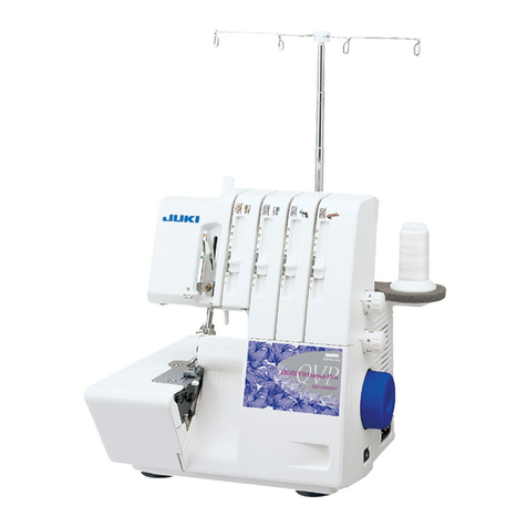
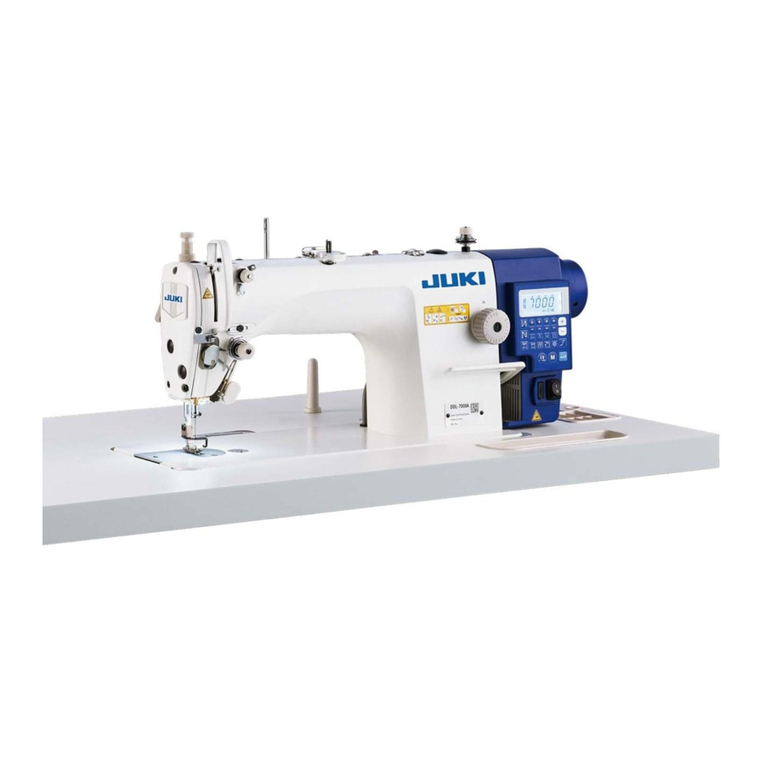
JUKI LK-1900B series Quick start guide

40145045
No. E414-03
ENGINEER’S MANUAL
LK-1900B Series
Computer-controlled High-speed Bartacking Machine
(LK-1900B, LK-1901B, LK-1902B, LK-1903B, LK-1900BB, LK-1903BB,
LK-1900BN, LK-1901BN, LK-1902BN, LK-1903BN, LK-1900BNB,
LK-1903BNB)

PREFACE
This Engineer’s Manual is written for the technical personnel who are responsible for the service and
maintenance of the machine.
The Instruction Manual for these machines intended for the maintenance personnel and operators at
an apparel factory contains operating instruction in detail. And this manual describes “Standard Adjust-
ment”, “Adjustment Procedures”, “Results of Improper Adjustment”, and other important information
which are not covered in the Instruction Manual.
When carrying out the maintenance work on the sewing machine, be sure to refer also to the Instruction
Manual and the Parts List.
In addition, for the motor for the sewing machine with thread trimmer, refer to the separate Instruction
Manual or This manual gives the “Standard Adjustment” on the former page under which the most basic
adjustment value is described, and on the latter page “Results of Improper Adjustment” under which
stitching errors and troubles arising from mechanical failures and “How to adjust” are described.

i
For the sewing machine, automatic machine and ancillary devices (hereinafter collectively referred to as
"machine"), it is inevitable to conduct sewing work near moving parts of the machine. This means that there
is always a possibility of unintentionally coming in contact with the moving parts. Operators who actually
operate the machine and maintenance personnel who are involved in maintenance and repair of the machine
are strongly recommended to carefully read to fully understand the following Safety precautions of this
engineer's manual before using/maintaining the machine. The content of the Safety precautions of this
engineer's manual includes items which are not contained in the specications of your product.
The risk indications are classied into the following three different categories to help understand the meaning
of the labels of this engineer's manual and the product. Be sure to fully understand the following description
and strictly observe the instructions.
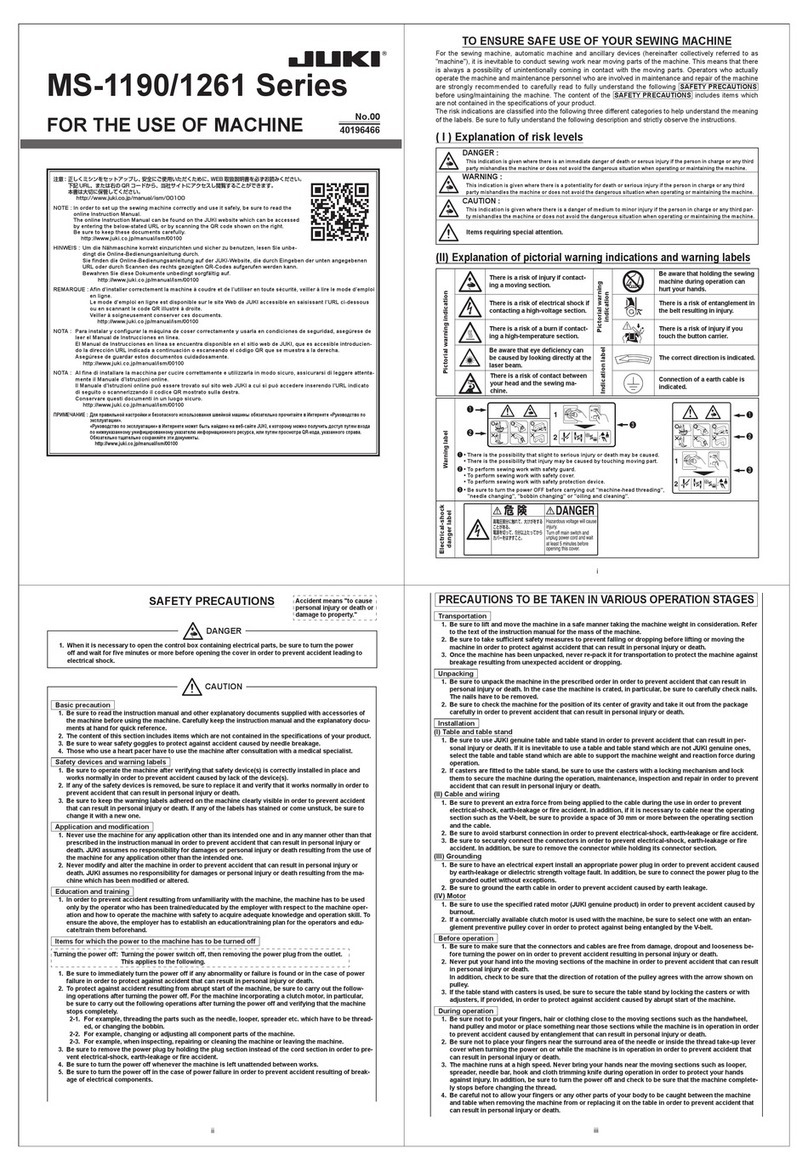
( I ) Explanation of risk levels
( II )
Explanation of pictorial warning indications and warning labels
Warning label
❶
❷
❸
❶
• There is the possibility that slight to serious injury or death may be caused.
• There is the possibility that injury may be caused by touching moving part.
❷• To perform sewing work with safety guard.
• To perform sewing work with safety cover.
• To perform sewing work with safety protection device.
❸
• Be sure to turn the power OFF before carrying out "machine-head threading,"
"needle changing," "bobbin changing" or "oiling and cleaning.
❸
❷
❶
Electrical-shock
danger label
DANGER :
This indication is given where there is an immediate danger of death or serous injury if the person in charge or any third
party mishandles the machine or does not avoid the dangerous situation when operating or maintaining the machine.
WARNING :
This indication is given where there is a potentiality for death or serious injury if the person in charge or any third party
mishandles the machine or does not avoid the dangerous situation when operating or maintaining the machine.
CAUTION :
This indication is given where there is a danger of medium to minor injury if the person in charge or any third party
mishandles the machine or does not avoid the dangerous situation when operating or maintaining the machine.
Items requiring special attention
Pictorial warning indication
There is a risk of injury if contact-
ing a moving section.
Pictorial warning
indication
Be aware that holding the sewing
machine during operation can
hurt your hands.
There is a risk of electrical shock if
contacting a high-voltage section.
There is a risk of entanglement
in the belt resulting in injury.
There is a risk of a burn if contact-
ing a high-temperature section.
There is a risk of injury if you
touch the button carrier.
Be aware that eye deciency can
be caused by looking directly at
the laser beam.
Indication label
The correct direction is indicat-
ed.
There is a risk of contact between
your head and the sewing ma-
chine.
Connection of a earth cable is
indicated.
TO ENSURE SAFE USE OF YOUR SEWING MACHINE
Adjustment :
It means replacement of parts,
disassembly, and repair assembly.

ii
Basic precaution
1. Be sure to read the engineer's manual and other explanatory documents supplied with accessories of
the machine before using the machine. Carefully keep the engineer's manual and the explanatory docu-
ments at hand for quick reference.
2. The content of this section includes items which are not contained in the specications of your product.
3. Be sure to wear safety goggles to protect against accident caused by needle breakage.
4. Those who use a heart pacer have to use the machine after consultation with a medical specialist.
5. Turn OFF the power before starting the work in order to protect against accident that can result in per-
sonal injury.
If it is inevitable to carry out work with the power ON, utmost care should be taken to prevent from de-
pressing the foot pedal or pressing the start switch by mistake.
6. Make sure, after the completion of replacement work, that neither connectors nor cables are damaged,
slipped off or loosened in order to protect against accident that can result in personal injury.
Safety devices and warning labels
1. Be sure to operate the machine after verifying that safety device(s) is correctly installed in place and
works normally in order to prevent accident caused by lack of the device(s).
2. If any of the safety devices is removed, be sure to replace it and verify that it works normally in order to
prevent accident that can result in personal injury or death.
3. Be sure to keep the warning labels adhered on the machine clearly visible in order to prevent accident
that can result in personal injury or death. If any of the labels has stained or come unstuck, be sure to
change it with a new one.
Application and modication
1.
Never use the machine for any application other than its intended one and in any manner other than that
prescribed in the engineer's manual in order to prevent accident that can result in personal injury or death.
JUKI assumes no responsibility for damages or personal injury or death resulting from the use of the
machine for any application other than the intended one.
2.
Never modify and alter the machine in order to prevent accident that can result in personal injury or death.
JUKI assumes no responsibility for damages or personal injury or death resulting from the machine
which has been modied or altered.
Education and training
1. In order to prevent accident resulting from unfamiliarity with the machine, the machine has to be used
only by the operator who has been trained/educated by the employer with respect to the machine oper-
ation and how to operate the machine with safety to acquire adequate knowledge and operation skill. To
ensure the above, the employer has to establish an education/training plan for the operators and edu-
cate/train them beforehand.
Items for which the power to the machine has to be turned off
Turning the power off: Turning the power switch off, then removing the power plug from the outlet. This
applies to the following.
1. Be sure to immediately turn the power off if any abnormality or failure is found or in the case of power
failure in order to protect against accident that can result in personal injury or death.
2. To protect against accident resulting from abrupt start of the machine, be sure to carry out the follow-
ing operations after turning the power off. For the machine incorporating a clutch motor, in particular,
be sure to carry out the following operations after turning the power off and verifying that the machine
stops completely.
2-1. For example, threading the parts such as the needle, looper, spreader etc. which have to be thread-
ed, or changing the bobbin.
2-2. For example, changing or adjusting all component parts of the machine.
2-3. For example, when inspecting, repairing or cleaning the machine or leaving the machine.
3. Be sure to remove the power plug by holding the plug section instead of the cord section in order to pre-
vent electrical-shock, earth-leakage or re accident.
4. Be sure to turn the power off whenever the machine is left unattended between works.
5. Be sure to turn the power off in the case of power failure in order to prevent accident resulting of break-
age of electrical components.
PRECAUTIONS TO BE TAKEN IN VARIOUS OPERATION STAGES
Accident means "to cause
personal injury or death or
damage to property."
CAUTION
DANGER
SAFETY PRECAUTIONS
1.
When it is necessary to open the control box containing electrical parts, be sure to turn the power off and
wait for ve minutes or more before opening the cover in order to prevent accident leading to electrical
shock.

iii
Transportation
1. Be sure to lift and move the machine in a safe manner taking the machine weight in consideration. Refer
to the text of the engineer's manual for the mass of the machine.
2. Be sure to take sufcient safety measures to prevent falling or dropping before lifting or moving the
machine in order to protect against accident that can result in personal injury or death.
3. Once the machine has been unpacked, never re-pack it for transportation to protect the machine against
breakage resulting from unexpected accident or dropping.
Unpacking
1. Be sure to unpack the machine in the prescribed order in order to prevent accident that can result in
personal injury or death. In the case the machine is crated, in particular, be sure to carefully check nails.
The nails have to be removed.
2. Be sure to check the machine for the position of its center of gravity and take it out from the package
carefully in order to prevent accident that can result in personal injury or death.
Installation
(I) Table and table stand
1.
Be sure to use JUKI genuine table and table stand in order to prevent accident that can result in personal
injury or death. If it is inevitable to use a table and table stand which are not JUKI genuine ones, select the
table and table stand which are able to support the machine weight and reaction force during operation.
2. If casters are tted to the table stand, be sure to use the casters with a locking mechanism and lock
them to secure the machine during the operation, maintenance, inspection and repair in order to prevent
accident that can result in personal injury or death.
(II) Cable and wiring
1.
Be sure to prevent an extra force from being applied to the cable during the use in order to prevent electri-
cal-shock, earth-leakage or re accident. In addition, if it is necessary to cable near the operating section
such as the V-belt, be sure to provide a space of 30 mm or more between the operating section and the cable.
2. Be sure to avoid starburst connection in order to prevent electrical-shock, earth-leakage or re accident.
3. Be sure to securely connect the connectors in order to prevent electrical-shock, earth-leakage or re
accident. In addition, be sure to remove the connector while holding its connector section.
(III) Grounding
1. Be sure to have an electrical expert install an appropriate power plug in order to prevent accident caused
by earth-leakage or dielectric strength voltage fault. In addition, be sure to connect the power plug to the
grounded outlet without exceptions.
2. Be sure to ground the earth cable in order to prevent accident caused by earth leakage.
(IV) Motor
1. Be sure to use the specied rated motor (JUKI genuine product) in order to prevent accident caused by
burnout.
2. If a commercially available clutch motor is used with the machine, be sure to select one with an entan-
glement preventive pulley cover in order to protect against being entangled by the V-belt.
Before operation
1. Be sure to make sure that the connectors and cables are free from damage, dropout and looseness be-
fore turning the power on in order to prevent accident resulting in personal injury or death.
2. Never put your hand into the moving sections of the machine in order to prevent accident that can result
in personal injury or death.
In addition, check to be sure that the direction of rotation of the pulley agrees with the arrow shown on
pulley.
3. If the table stand with casters is used, be sure to secure the table stand by locking the casters or with
adjusters, if provided, in order to protect against accident caused by abrupt start of the machine.
During operation
1. Be sure not to put your ngers, hair or clothing close to the moving sections such as the handwheel,
hand pulley and motor or place something near those sections while the machine is in operation in order
to prevent accident caused by entanglement that can result in personal injury or death.
2. Be sure not to place your ngers near the surround area of the needle or inside the thread take-up lever
cover when turning the power on or while the machine is in operation in order to prevent accident that
can result in personal injury or death.
3. The machine runs at a high speed. Never bring your hands near the moving sections such as looper,
spreader, needle bar, hook and cloth trimming knife during operation in order to protect your hands
against injury. In addition, be sure to turn the power off and check to be sure that the machine complete-
ly stops before changing the thread.
4. Be careful not to allow your ngers or any other parts of your body to be caught between the machine
and table when removing the machine from or replacing it on the table in order to prevent accident that
can result in personal injury or death.
5.
Be sure to turn the power off and check to be sure that the machine and motor completely stop before re-
moving the belt cover and V-belt in order to prevent accident caused by abrupt start of the machine or motor.
6.
If a servomotor is used with the machine, the motor does not produce noise while the machine is at rest.
Be sure not to forget to turn the power off in order to prevent accident caused by abrupt start of the motor.
7. Never use the machine with the cooling opening of the motor power box shielded in order to prevent re
accident by overheat.
iv
Lubrication
1. Be sure to use JUKI genuine oil and JUKI genuine grease to the parts to be lubricated.
2. If the oil adheres on your eye or body, be sure to immediately wash it off in order to prevent inamma-
tion or irritation.
3. If the oil is swallowed unintentionally, be sure to immediately consult a medical doctor in order to pre-
vent diarrhea or vomiting.
Maintenance
1. In prevention of accident caused by unfamiliarity with the machine, repair and adjustment has to be car-
ried out by a service technician who is thoroughly familiar with the machine within the scope dened in
the engineer's manual. Be sure to use JUKI genuine parts when replacing any of the machine parts. JUKI
assumes no responsibility for any accident caused by improper repair or adjustment or the use of any
part other than JUKI genuine one.
2. In prevention of accident caused by unfamiliarity with the machine or electrical-shock accident, be sure
to ask an electrical technician of your company or JUKI or distributor in your area for repair and mainte-
nance (including wiring) of electrical components.
3. When carrying out repair or maintenance of the machine which uses air-driven parts such as an air cyl-
inder, be sure to remove the air supply pipe to expel air remaining in the machine beforehand, in order to
prevent accident caused by abrupt start of the air-driven parts.
4. Be sure to check that screws and nuts are free from looseness after completion of repair, adjustment
and part replacement.
5. Be sure to periodically clean up the machine during its duration of use. Be sure to turn the power off
and verify that the machine and motor stop completely before cleaning the machine in order to prevent
accident caused by abrupt start of the machine or motor.
6. Be sure to turn the power off and verify that the machine and motor stop completely before carrying out
maintenance, inspection or repair of the machine. (For the machine with a clutch motor, the motor will
keep running for a while by inertia even after turning the power off. So, be careful.)
7. If the machine cannot be normally operated after repair or adjustment, immediately stop operation and
contact JUKI or the distributor in your area for repair in order to prevent accident that can result in per-
sonal injury or death.
8. If the fuse has blown, be sure to turn the power off and eliminate the cause of blowing of the fuse and
replace the blown fuse with a new one in order to prevent accident that can result in personal injury or
death.
9. Be sure to periodically clean up the air vent of the fan and inspect the area around the wiring in order to
prevent re accident of the motor.
10. In order to prevent accidents resulting in personal injury or death, adjustments have to be carried out
within the instructions described in this Engineer's Manual and in the Instruction Manual by the person-
nel who have been well trained by the employer with respect to the latest knowledge and safety for the
machine.
11. Make sure that water is contained in cylinders and pipes, then remove water from them in order to pre-
vent accidents due to a malfunction of the machine.
Operating environment
1. Be sure to use the machine under the environment which is not affected by strong noise source (electro-
magnetic waves) such as a high-frequency welder in order to prevent accident caused by malfunction of
the machine.
2. Never operate the machine in any place where the voltage uctuates by more than "rated voltage ±10 %"
in order to prevent accident caused by malfunction of the machine.
3. Be sure to verify that the air-driven device such as an air cylinder operates at the specied air pressure
before using it in order to prevent accident caused by malfunction of the machine.
4. To use the machine with safety, be sure to use it under the environment which satises the following
conditions:
Ambient temperature during operation 5°C to 35°C
Relative humidity during operation 35 % to 85 %
5. Dew condensation can occur if bringing the machine suddenly from a cold environment to a warm one.
So, be sure to turn the power on after having waited for a sufcient period of time until there is no sign
of water droplet in order to prevent accident caused by breakage or malfunction of the electrical compo-
nents.
6. Be sure to stop operation when lightning ashes for the sake of safety and remove the power plug in
order to prevent accident caused by breakage or malfunction of the electrical components.
7. Depending on the radio wave signal condition, the machine may generate noise in the TV or radio. If this
occurs, use the TV or radio with kept well away from the machine.
8. In order to ensure the work environment, local laws and regulations in the country where the sewing
machine is installed shall be followed.
In the case the noise control is necessary, an ear protector or other protective gear should be worn ac-
cording to the applicable laws and regulations.
9. Disposal of products and packages and treatment of used lubricating oil should be carried out properly
according to the relevant laws of the country in which the sewing machine is used.

v
Transportation
1. Be sure to lift this machine with four or more workers and use a carriage for moving it in order to pre-
vent personal injury.
2. Be sure to take sufcient safety measures to prevent falling or dropping before lifting or moving the
machine in order to protect against accident that can result in personal injury or death.
3. Installation is described in the Instruction Manual. Be sure to fully understand the description before
putting the machine into operation.
Replacement of parts
1. In prevention of accident that can result in personal injury, be sure to carry out disassembly/assembly
work within the specied range given in this Engineer's Manual and in the Instruction Manual.
2. Turn OFF the power before starting the work in order to protect against accident that can result in per-
sonal injury.
If it is inevitable to carry out work with the power ON, utmost care should be taken to prevent from de-
pressing the foot pedal or pressing the start switch by mistake.
3. Be sure to carry out replacement work after having installed the machine in a stable state in order to
protect against accident that can result in personal injury.
In addition, be sure to select appropriate tools.
4. In prevention of accident that can result in personal injury, make sure, after the completion of adjust-
ment work, that neither screws nor nuts are loosened or come in contact with other parts.
5. Be sure to use JUKI genuine parts when replacing any of the machine parts.
JUKI assumes no responsibility for any accident caused by any part other than JUKI genuine one.
In addition, in the event you cannot replace parts within the specied range, immediately stop the re-
placement work and ask JUKI or distributor in your area for replacement of the parts.
Adjustment
1. Be sure to adjust according to the instructions given in this Engineer's Manual and in the Instruction
Manual in order to protect against accident that can result in personal injury.
2. Be sure to carry out replacement work after having installed the machine in a stable state in order to
protect against accident that can result in personal injury.
In addition, be sure to select appropriate tools.
3. In prevention of accident that can result in personal injury, make sure, after the completion of adjust-
ment work, that neither screws nor nuts are loosened or come in contact with other parts.
4. Turn OFF the power before starting the work in order to protect against accident that can result in per-
sonal injury.
If it is inevitable to carry out work with the power ON, utmost care should be taken to prevent from de-
pressing the foot pedal or pressing the start switch by mistake.
5. In prevention of accident that can result in personal injury or entanglement accident, be sure to ensure
safety at the time of test run. In addition, be sure to take care not to allow hair or cloths to come in con-
tact with the machine belt.
Disassembly/assembly
1. In prevention of accident that can result in personal injury, be sure to carry out disassembly/assembly
work within the specied range given in this Engineer's Manual and in the Instruction Manual.
2. Be sure to carry out replacement work after having installed the machine in a stable state in order to
protect against accident that can result in personal injury.
In addition, be sure to select appropriate tools.
3. In prevention of accident that can result in personal injury, make sure, after the completion of adjust-
ment work, that neither screws nor nuts are loosened or come in contact with other parts.
4. In prevention of accident that can result in personal injury, be sure to tighten screws and nuts in assem-
bly work with a specied torque, if specied, or with an appropriate torque, if not specied.
After the completion of assembly work, be sure to check that screws and nuts are not loosened before
starting test run.
5. In prevention of accident that can result in personal injury, be sure to check whether the direction of
rotation is correct at the time of test run.
6. In prevention of accident that can result in personal injury or entanglement accident, be sure to ensure
safety at the time of test run. In addition, be sure to take care not to allow hair or cloths to come in con-
tact with the machine belt.
PRECAUTIONS TO BE TAKEN IN VARIOUS OPERATION STAGES
Mechanical components
CAUTION

vi
Transportation
1. Be sure to lift this machine with four or more workers and use a carriage for moving it in order to pre-
vent personal injury.
2. Be sure to take sufcient safety measures to prevent falling or dropping before lifting or moving the
machine in order to protect against accident that can result in personal injury or death.
3. Installation is described in the Instruction Manual. Be sure to fully understand the description before
putting the machine into operation.
Replacement of parts
1. In prevention of accident caused by unfamiliarity with the machine or electrical-shock accident, be sure
to ask an electrical technician of your company or JUKI or distributor in your area for replacement of
electrical components.
2. When it is necessary to open the control box containing electrical parts, be sure to turn the power off
and wait for ve minutes or more before opening the cover in order to prevent accident caused by un-
familiarity with the machine or electrical-shock accident. In addition, do not carry out replacement work
with wet hands in order to prevent electrical-shock accident.
3. Be sure to replace parts according to the instructions given in this Engineer's Manual and in the Instruc-
tion Manual in order to protect against accident that can result in personal injury.
4. Be sure to carry out replacement work after having installed the machine in a stable state in order to
protect against accident that can result in personal injury.
In addition, be sure to select appropriate tools.
5. Make sure, after the completion of replacement work, that there is no loose soldering, no contact with
other parts, inadequate contact between connectors and receptacles, and loose screws/nuts in order to
protect against accident that can result in personal injury.
6. Make sure, after the completion of replacement work, that neither connectors nor cables are damaged,
slipped off or loosened in order to protect against accident that can result in personal injury.
It should be remembered that some parts have been factory-insulated with tubes or tapes, or oated
above the PWB for safety's sake. In addition, internal wiring has been factory-routed or -clamped in such
a way that it does not come close to high-voltage parts. Be sure to re-place those parts as they are at the
time of delivery.
7. Be sure to use JUKI genuine parts when replacing any of the machine parts.
JUKI assumes no responsibility for any accident caused by any part other than JUKI genuine one.
In addition, in the event you cannot replace parts within the specied range, immediately stop the re-
placement work and ask JUKI or distributor in your area for replacement of the parts.
8. If the fuse has blown, be sure to turn the power off and eliminate the cause of blowing of the fuse and
replace the blown fuse with a new one in order to prevent accident that can result in personal injury or
death.
Adjustment
1. In prevention of accident caused by unfamiliarity with the machine or electrical-shock accident, be sure
to ask an electrical technician of your company or JUKI or distributor in your area for adjustment of
electrical components.
2. When it is necessary to open the control box containing electrical parts, be sure to turn the power off
and wait for ve minutes or more before opening the cover in order to prevent accident caused by un-
familiarity with the machine or electrical-shock accident. In addition, do not carry out adjustment work
with wet hands in order to prevent electrical-shock accident.
3. In prevention of accident that can result in personal injury, adjust adjustment variable resistor or the like
installed on PWB within the specied range given in this Engineer's Manual and in the Instruction Manu-
al.
4. Be sure to carry out replacement work after having installed the machine in a stable state in order to
protect against accident that can result in personal injury.
In addition, be sure to select appropriate tools.
5. In prevention of accident that can result in personal injury, make sure, after the completion of adjust-
ment work, that neither screws nor nuts are loosened or come in contact with other parts.
6. Make sure, after the completion of replacement work, that neither connectors nor cables are damaged,
slipped off or loosened in order to protect against accident that can result in personal injury.
7. In prevention of accident that can result in personal injury or entanglement accident, be sure to ensure
safety at the time of test run. In addition, be sure to take care not to allow hair or cloths to come in con-
tact with the machine belt.
Disassembly/assembly
1. In prevention of accident that can result in personal injury, be sure to carry out disassembly/assembly
work within the specied range given in this Engineer's Manual and in the Instruction Manual.
PRECAUTIONS TO BE TAKEN IN VARIOUS OPERATION STAGES
Electrical components
CAUTION

vii
2. In prevention of accident caused by unfamiliarity with the machine or electrical-shock accident, be sure
to ask an electrical technician of your company or JUKI or distributor in your area for disassembly/as-
sembly of electrical components.
3. When it is necessary to open the control box containing electrical parts, be sure to turn the power off
and wait for ve minutes or more before opening the cover in order to prevent accident caused by unfa-
miliarity with the machine or electrical-shock accident. In addition, do not carry out disassembly/assem-
bly work with wet hands in order to prevent electrical-shock accident.
4. Be sure to carry out replacement work after having installed the machine in a stable state in order to
protect against accident that can result in personal injury.
In addition, be sure to select appropriate tools.
5. In prevention of accident that can result in personal injury, be sure to tighten screws and nuts in assem-
bly work with a specied torque, if specied, or with an appropriate torque, if not specied.
After the completion of assembly work, be sure to check that screws and nuts are not loosened before
starting test run.
6. In prevention of accident that can result in personal injury, make sure, after the completion of adjust-
ment work, that neither screws nor nuts are loosened or come in contact with other parts.
7. Make sure, after the completion of replacement work, that neither connectors nor cables are damaged,
slipped off or loosened in order to protect against accident that can result in personal injury.
It should be remembered that some parts have been factory-insulated with tubes or tapes, or oated
above the PWB for safety's sake. In addition, internal wiring has been factory-routed or -clamped in such
a way that it does not come close to high-voltage parts. Be sure to re-place those parts as they are at the
time of delivery.
8. In prevention of accident that can result in personal injury, be sure to check whether the direction of
rotation is correct at the time of test run.
9. In prevention of accident that can result in personal injury or entanglement accident, be sure to ensure
safety at the time of test run. In addition, be sure to take care not to allow hair or cloths to come in con-
tact with the machine belt.

viii
PRECAUTIONS TO BE TAKEN SO AS TO USE
THE LK-1900B SERIES MORE SAFELY
1. To avoid electrical shock hazards, neither open the cover of the electrical box for the mo-
tor nor touch the components mounted inside the electrical box.
2. After changing the pattern, make sure the needle entry point. If the pattern is protruded
from the work clamp feet, the needle will interfere with the work clamp feet during sew-
ing, and it is dangerous due to the needle breakage or the like.
3. Do not turn OFF the power in a state that the needle is lowered. Wiper may break the nee-
dle.
1. In case nothing is displayed in the operation panel even when the power switch is turned
ON, turn OFF the power switch and check the power voltage and phase.
2. To prevent personal injury or death, never put ngers into the thread take-up lever, work
clamp, work clamp mechanism and thread take-up cover, and under or near the cloth cut-
ting knife and needle when turning on the power switch or while the machine is in opera-
tion.
3. To protect against possible accidents due to abrupt startup of the machine, turn OFF the
power switch before tilting the machine head or removing the motor cover.
4. So as to prevent possible accidents caused by abrupt start of the sewing machine, de-
press the start switch after ascertaining that there is no interfering thing under the needle
when winding the bobbin thread. In addition, never put your hair close to the machine
during thread trimming.
5. Feeding frame automatically comes down when pattern is changed, ready key is ON,
Presser switch is ON, intermediate presser button is ON and bobbin winder button is ON.
To prevent possible accidents caused by abrupt start of the sewing machine, never place
your ngers under the feeding frame.
6. To avoid personal injury, never bring your ngers, hair or clothing close to V belt, cloth
cutting knife or motor during operation, and never place anything on any of these parts.
7. To avoid personal injury, never operate the machine with the motor cover, eye protection
cover, or any other safety devices removed.
8. To prevent personal injury or death, do not operate the sewing machine with its covers
removed.
9. The operation panel displays safety warnings. It is necessary therefore to rst verify
normal display on the panel when the power switch is turned on, before operating the
sewing machine.
10. To prevent personal injury or death, do not press the hand pulley while the sewing ma-
chine is in operation.
11. To avoid personal injury, be careful never to allow your ngers to go inside the machine
when tilting or raising the machine head.
12. To prevent possible accidents due to electric shocks or damaged electrical compo-
nent(s), always turn OFF the power switch before connecting or disconnecting the
power plug.

ix
13. During thunder and lightning storms, stop your work and disconnect the power from the
outlet to ensure safety and prevent possible accidents due to damaged electrical compo-
nent(s).
14. If the machine is suddenly moved from a cold place to a warm place, dew condensation
may result. If this occurs, be sure to conrm that there are no potentially dangerous wa-
ter drops in the machine before turning it on in order to prevent possible accidents due
to damaged electrical component(s).
15. In the event of a power failure, be sure to turn OFF the power to the machine to protect
against damaged electrical components.
16. This sewing machine should be used under industrial environment. Under general house-
hold environment, the machine may cause poor reception when used in proximity of the
television set or radio.
17. When the sewing machine is used without a break for many hours, the temperature of a
part of the machine body or the rear side of operation panel rises higher by 15˚C than the
environmental temperature, and you may feel the heat from the part. However, this phe-
nomenon is not abnormal, and does not affect the components or the like.
18. Do not lubricate the machine oil to the places other than the oil tank and the hook sec-
tion. The grease lubricating system except the hook section is employed for this sewing
machine, and the grease ows out when lubricating the machine oil resulting in worn-out
of the components.
19. Be careful of handling this product so as not to pour water or oil, shock by dropping, and
the like since this product is a precision instrument.
20. This is a Class A product. In a domestic environment this product may cause radio inter-
ference, in which case the user may be required to make corrective actions.
21. In order to prevent possible accidents due to a ground fault, the earth cable should be
properly grounded.
22. For the control box to be connected to the LK-1900B Series, use the exclusive control
box for the LK-1900B Series.

x
In addition, be aware that the safety devices such as the "eye protection cover" and "nger guard"
are sometimes omitted in the sketches, illustrations and gures included in the Engineer's Manual
for the explanation's sake. In the practical use, never remove those safety devices.
CAUTION
SAFETY DEVICES AND WARNING LABELS
Warning label (Refer to
the warn-
ing label
on page i.)
The label gives the min-
imum precautions to be
taken when operating
the sewing machine.
Warning label
against pinching
This label warns
that ngers or
other parts of
human body can
be pinched in the
thread take-up
lever.
Power switch
This is a switch for discon-
necting the power unit of the
sewing machine from the pow-
er supply.
Power switch (EU type)
This switch is used
for disconnecting
the power unit of the
sewing machine from
the power supply. It is
also used as the emer-
gency stop switch.
Selection of the power switch
Use the IEC60204-1-compliant
power switch with rated current
of 20 A or more and short-circuit
breaking capacity of 120 A or
more, which has the operating
section in red against the yellow
background.
Eye protection
cover
This is a cover
for protecting
eyes from being
injured by a
broken needle.
Finger guard
This is a cover
for preventing
contact between
ngers and the
needle.
Motor cover
This is a cover for
preventing contact
between the human
body and the motor.
Thread take-up
lever cover
This is a cover
for preventing
contact between
the human body
and the thread
take-up lever.
Warning label
against pinching
This label warns
that hands can be
pinched under the
sewing machine.
Electrical-shock danger label
(EU type)
(Refer to "Electri-
cal-shock danger
label" on page i.)
In order to protect against
electrical shock, safety precau-
tions to be taken to avoid dan-
ger are written on this label.

xi
CONTENTS
1.Specications ................................................................................................................................ 1
2.Conguration ................................................................................................................................. 5
(1)Namesofmainunit....................................................................................................................................................... 5
(2)Namesandexplanationofswitchesontheoperationpanel ................................................................................... 6
3.Standardadjustmentvalue........................................................................................................... 8
(1)Mainshaftconnection/disconnection ........................................................................................................................ 8
(2)Removalofthemainshaftmotorandcoupling ...................................................................................................... 10
(3)
Crankconnectingrodconnection/disconnection
....................................................................................................... 12
(4)Crankbalancerpositioning ....................................................................................................................................... 14
(5)Lowershaftbacklashadjustmentandconnection/disconnection ........................................................................ 14
(6)Oscillatorgearpositioning ........................................................................................................................................ 16
(7)Adjustmentofhookoilamount................................................................................................................................. 16
(8)Shuttleconnection/disconnectionandoilwickpiping........................................................................................... 18
(9)Adjustmenttheheightoftheneedlebar .................................................................................................................. 18
(10)Hookadjustment........................................................................................................................................................ 20
(11)Threadtrimmercampositionadjustmentandconnection/disconnection........................................................... 22
(12)Threadtrimmer/workclampfootoriginsensoradjustment .................................................................................. 22
(13)Adjustmentoftheheightoftheworkclampfoot ................................................................................................... 24
(14)Adjustmentofthethreadtrimmersensor ............................................................................................................... 24
(15)Adjustmentofthemovingknifeandcounterknifeposition ................................................................................. 26
(16)Adjustmentoftheheightofthemovingknifeandcounterknife.......................................................................... 26
(17)Inclinationofthebladepointofthecounterknife.................................................................................................. 28
(18)Floatingamountofthethreadtensiondisk ............................................................................................................ 28
(19)Secondthreadtensionconnection/disconnection................................................................................................. 30
(20)ATunitconnection/disconnection ........................................................................................................................... 32
(21)Positionofthemechanicalorigin............................................................................................................................. 34
(22)AdjustmentoftheYorigin ........................................................................................................................................ 34
(23)AdjustmentoftheXorigin ........................................................................................................................................ 36
(24)Adjustmentofthewiperposition ............................................................................................................................. 36
(25)Adjustmentofthewiperspring(LK-1903B,1903BN)............................................................................................. 38
(26)AdjustmentofthepositionoftheXfeedmotorandtheYfeedmotor
(Adjustmentofthebacklashofthedrivinggear) ................................................................................................... 38
(27)Installingthefeedplatesupportplate ..................................................................................................................... 40
(28)Installationofthefeederbarrearcover................................................................................................................... 40
(29)Adjustmentofthebobbinwinderdrivingwheelposition...................................................................................... 42
(30)Adjustmentofthebobbinwinderamount............................................................................................................... 42
(31)Adjustmentoftheshuttleupperspringposition
(ExceptforLK-1900B-BS,1900B-BF,1903B-BS,1900BN-BS,1900BN-BFand1903BN-BS)............................... 44
(32)Shuttlefelt................................................................................................................................................................... 44
(33)Shapeoftheinnerhookpresser .............................................................................................................................. 46
(34)Adjustmentofthethreadtake-upspring................................................................................................................. 46
(35)Needlethreadclampdeviceconnection/disconnection ........................................................................................ 48
(36)Adjustmentoftheneedlethreadclampreferenceposition................................................................................... 50
(37)Adjustmentoftheneedlethreadclampnotch........................................................................................................ 52
(38)
Assemblingtheshorterthreadremainingunit
........................................................................................................ 54
(39)Assemblingthemovingknifedrivesectionofshorterthreadremaining............................................................ 54
(40)Assemblingthesuctionpipe .................................................................................................................................... 56
(41)Adjustmentoftheshuttleupperspringposition(LK-1903B-BS,1900B-BS,1900B-BF,1903BN-BS,
1900BN-BS,1900BN-BF)andthelowerthreadholderposition(LK-1903BN-BS) ............................................... 58
(42)Bobbincasewithanidlingpreventionspring ........................................................................................................ 60
4.Descriptionofthefunctions....................................................................................................... 61
(1)Tousethefunctionsoftheservicepersonlevel...................................................................................................... 61
(2)Contrastadjustment................................................................................................................................................... 62
(3)USBformat .................................................................................................................................................................. 62
(4)Keylocksetting .......................................................................................................................................................... 63
(5)Howtochecktheversioninfoemation ..................................................................................................................... 65
(6)Howtousethecommunicationfunction(CommunicationfunctionsotherthanNFC)....................................... 66
(7)RegisteringanNFCterminal ..................................................................................................................................... 70
(8)PatternselectionfromtheUSBthumbdrive ........................................................................................................... 73
5.Memoryswitches......................................................................................................................... 74
(1)Memoryswitchstartandchange .............................................................................................................................. 74
(2)Tableofmemoryswitchfunctions............................................................................................................................ 75
(3)Supplementforthememoryswitch.......................................................................................................................... 82

xii
6.Check program ............................................................................................................................ 84
(1)Starting the Check program ...................................................................................................................................... 84
(2)Input signal check ...................................................................................................................................................... 85
(3)X/Y motor origin adjustment...................................................................................................................................... 86
(4)Continuous operation ................................................................................................................................................ 87
(5)Main motor rpm check ............................................................................................................................................... 88
(6)Output check............................................................................................................................................................... 88
(7)Work clamp foot/thread trimming motor origin adjustment................................................................................... 89
(8)
Needle thread clamp motor origin adjustment
......................................................................................................... 90
7.Miscellaneous .............................................................................................................................. 91
(1)Various printed wiring boards ................................................................................................................................... 91
(2)Tableofbar-tackingstandardpatternspecications ............................................................................................. 96
(3)Table of standard patterns......................................................................................................................................... 97
8.Sub-class information ................................................................................................................. 99
(1)Modelsclassiedbybuttonsizes(LK-1903B)......................................................................................................... 99
(2)TableofStandardPatterns(LK-1903B) .................................................................................................................. 100
(3)Option (LK-1900BB,1903BB,1900BNB,1903BNB)............................................................................................... 100
9.Optional features ....................................................................................................................... 101
(1)Table of optional parts ............................................................................................................................................. 101
(2)Connection of the optional pedal............................................................................................................................ 103
(3)Connectionofthemagnetwiper(cannotbeconnectedwithLK-1901B)............................................................ 107
(4)Connection of the pause switch.............................................................................................................................. 107
(5)Connection of the marking light.............................................................................................................................. 108
(6)Connection of the needle cooler (turns ON while machine is running) .............................................................. 109
(7)Table of the work clamp foot ................................................................................................................................... 110
10.Maintenance............................................................................................................................... 112
(1)Replacing the fuse.................................................................................................................................................... 112
(2)100Vspecicationchangeover ............................................................................................................................... 112
(3)Greasing parts .......................................................................................................................................................... 113
(4)Parts to which grease is applied ............................................................................................................................. 114
(5)Grease-upproceduresforthespeciedposition.................................................................................................. 122
11.Error list...................................................................................................................................... 123
12.Troublesandcorrectivemeasures .......................................................................................... 128
(1)Mechanical parts....................................................................................................................................................... 128
(2)Sewing conditions .................................................................................................................................................... 130
(3)Electrical components ............................................................................................................................................. 139
13.Circuit diagrams ........................................................................................................................ 147
(1)Blockdiagram_Standardspecication(MC-670) .................................................................................................. 147
(2)
Blockdiagram_LK-1900BB,1903BB(MC-672)
......................................................................................................... 148
(3)
Blockdiagram_NFCType(MC-672)
.......................................................................................................................... 149
(4)
Powersupplycircuitdiagram(Single-phase)
......................................................................................................... 150
(5)Powersupplycircuitdiagram(Single-phaseCE).................................................................................................. 151
(6)Powersupplycircuitdiagram(3-phase)................................................................................................................. 152
(7)Servomotorcircuitdiagram.................................................................................................................................... 153
(8)Stepping motor circuit diagram .............................................................................................................................. 154
(9)MAIN · Operation panel circuit diagram ................................................................................................................. 155
(10)Machine head sensor circuit diagram.................................................................................................................... 156
(11)Aircircuitdiagram(LK-1900BBand1903BBonly) ............................................................................................... 157
(12)PneumaticcircuitdiagramforLK-1900BB ............................................................................................................ 157
14.Table drawings........................................................................................................................... 158
(1)TabletypeforlongitudinalInstallation ................................................................................................................... 158
(2)TabletypeforlateralInstallation............................................................................................................................. 159

– 1 –
1. Specications
No.
Model name
Item
Application
LK-1900B LK-1901B LK-1902B LK-1903B
1 Application Bar-tacking Eyelet buttonhole
bar-tacking
Belt-loop
attaching
Lock stitch button sewing
(Caution)1.
2 Sewing area X-Direction (right, left) 40 mm;
Y-Direction (forward, backward) 30 mm
—————
3 Button size ————— Type: Round-shaped,atbutton
Size: ø8 to ø32 mm,
Standard (ø8 to ø20 mm)
4 Max. sewing speed * 3,200 sti/min max.
(*2,700 sti/min for the 2-fold
semi-rotary hook)
* 3,000 sti/min max.
(When sewing pitches are less
than 5 mm in X-direction and 3.5
mm in Y-direction)
* 2,700 sti/min max.
5 Stitch length 0.1 mm to 10.0 mm (Adjustable in 0.1 mm step)
6 Feed motion of work clamp foot Intermittent feed (2-shaft drive by stepping motor)
7 Needle bar stroke 41.2 mm 45.7 mm
8 Needle DP×5 #14, #16 DP×17 #14
DP×5 #11 (F, M)
(DP×17 #21 heavy-weight
material)
(DP×17 #21
heavy-weight
material)
9 Work clamp lifting system Stepping motor
10 Lifting (lift) amount of work-
clamp foot
Standard 14 mm, Max. 17 mm
(At the time of needle up by reverse run function)
Max. 13 mm
11 Number of standard patterns 51 patterns 3 patterns 6 patterns 50 patterns
12 Data communication USB
13 Wiper system Interlockly with work clamp foot lifter by stepping motor
14 Needle thread clamp device Standard : General 0 Standard : Disable 1 (Caution)1.
15 Needle thread tension Active tension (Electronic thread tension control mechanism)
16 Hook Standard semi-rotary hook
(2-fold semi-rotary hook)
Standard semi-rotary hook
17 Lubrication Hook : Minute-quantity lubrication
18 Lubricating oil JUKI NEW Defrix oil No.2 (equivalent to ISO VG32) (Lubrication system)
19 Grease
1. Penetration No. 2 lithium grease, 2. Templex N3, 3. JUKI Grease A
(Caution)2.
20 Memory medium Memory of MAIN board (80 Kbyte)
21 Number of stitches that can be
stored in memory
Max. 20,000 stitches
22 Enlarging/Reducing facility X-Direction, Y-Direction: 20 to 200% each (1% step)
23 Enlarging/Reducing method Pattern enlargement/reduction can be done by increasing/decreasing the stitch length
24 Sewing speed limitation 400 to 3,200 sti/min
(100 sti/min step)
(2,700 sti/min max. for the
2-fold semi-rotary hook)
400 to 3,000 sti/min
(100 sti/min step)
400 to 2,700 sti/min
(100 sti/min step)
25 Material clawing amount ————— Max. 3 mm ————— —————
26 Pattern selector facility Standard pattern : 51, User pattern : 1 to 200, Media pattern : 1 to 999
27 Bobbin thread counter Up/Down method (0 to 9999)
28 Sewing machine motor AC servo motor (Direct-drive system)
29 External dimensions W: 1,200 mm, L: 660 mm, H: 1,100 mm (Standard table stand applied)
30 Weight Machine head : 42 kg, Control box : 5.1 kg
31 Power consumption 250VA (Pattern No.1, 3,200 sti/min, Pause : 2 seconds)
32 Working temperature range 5°C to 35°C
33 Working humidity range 35% to 85% (No dew condensation permissible)
34 Power-supply voltage 3-phase 200V , Rated voltage ±10% , 50/60Hz
35 Noise - Equivalent continuous emission sound pressure level (LpA) at the workstation :
A-weighted value of 82 dB; (Includes KpA = 2.5 dB); according to ISO 10821- C.6.3 -ISO 11204
GR2 at 3,200 sti/min for the sewing cycle, 1.0s ON (Pattern : No.1).
- Sound power level (LWA) ;
A-weighted value of 89 dB; (Includes KWA = 2.5 dB); according to ISO 10821- C.6.3 -ISO 3744
GR2 at 3,200 sti/min for the sewing cycle, 1.0s ON (Pattern : No.1).
* Maximum sewing speed should be reduced according to the sewing conditions.
(Caution) 1.LK-1903Bissettoneedlethreadclampprohibited(nomotion)withmemoryswitchU035atthe
timeofstandarddelivery.
2.Greasetype,referto"10.-(3)Greasingparts".

– 2 –
No.
Model name
Item
Application
LK-1900BB
(with bird's nest preventing and shorter thread
remaining type thread trimmer)
LK-1903BB
(with bird's nest preventing and shorter thread
remaining type thread trimmer)
1 Application Bar-tacking Lock stitch button sewing
2 Sewing area X-Direction (right, left) 40 mm;
Y-Direction (forward, backward) 30 mm
—————
3 Button size ————— Type:Round-shaped,atbutton(fourholes,
two holes)
Size : ø8 to 20 mm
4 Max. sewing speed * 3,200 sti/min max. * 2,700 sti/min max.
5 Stitch length 0.1 mm to 10.0 mm (Adjustable in 0.1 mm step)
6 Feed motion of work clamp foot Intermittent feed (2-shaft drive by stepping motor)
7 Needle bar stroke 41.2 mm 45.7 mm
8 Needle DP×17 #14 (S)
DP×17 #11 (F)
DP×17 #11, 14
9 Work clamp lifting system Stepping motor
10 Lifting (lift) amount of work-
clamp foot
Standard 11 mm, Max. 14 mm
(At the time of needle up by reverse run function)
Max. 10 mm
11 Number of standard patterns 50 patterns 34 patterns
12 Data communication USB
13 Wiper system Interlockly with work clamp foot lifter by stepping motor
14 Needle thread clamp device Standard : General 0 (Caution)3.
15 Needle thread tension Active tension (Electronic thread tension control mechanism)
16 Hook Standard semi-rotary hook
17 Lubrication Hook : Minute-quantity lubrication
18 Lubricating oil JUKI NEW Defrix oil No.2 (equivalent to ISO VG32) (Lubrication system)
19 Grease
1. Penetration No. 2 lithium grease, 2. Templex N3, 3. JUKI Grease A
(Caution)2.
20 Memory medium Memory of MAIN board (80 Kbyte)
21 Number of stitches that can be
stored in memory
Max. 20,000 stitches
22 Enlarging/Reducing facility X-Direction, Y-Direction: 20 to 200% each (1% step)
23 Enlarging/Reducing method Pattern enlargement/reduction can be done by increasing/decreasing the stitch length
24 Sewing speed limitation 400 to 3,200 sti/min (100 sti/min step) 400 to 2,700 sti/min (100 sti/min step)
25 Material clawing amount ————— —————
26 Pattern selector facility Standard pattern : 50/34, User pattern : 1 to 200, Media pattern : 1 to 999
27 Bobbin thread counter Up/Down method (0 to 9999)
28 Sewing machine motor AC servo motor (Direct-drive system)
29 External dimensions W: 1,200 mm, L: 660 mm, H: 1,100 mm (Standard table stand applied)
30 Weight Machine head : 42 kg, Control box : 5.1 kg
31 Power consumption 250VA (Pattern No.1, 3,200 sti/min, Pause : 2 seconds)
32 Working temperature range 5°C to 35°C
33 Working humidity range 35% to 85% (No dew condensation permissible)
34 Power-supply voltage 3-phase 200V , Rated voltage ±10% , 50/60Hz
35 Noise - Equivalent continuous emission sound pressure level (LpA) at the workstation :
A-weighted value of 82 dB; (Includes KpA = 2.5 dB); according to ISO 10821- C.6.3 -ISO 11204
GR2 at 3,200 sti/min for the sewing cycle, 1.0s ON (Pattern : No.1).
- Sound power level (LWA) ;
A-weighted value of 89 dB; (Includes KWA = 2.5 dB); according to ISO 10821- C.6.3 -ISO 3744
GR2 at 3,200 sti/min for the sewing cycle, 1.0s ON (Pattern : No.1).
* Maximum sewing speed should be reduced according to the sewing conditions.
(Caution) 2.Greasetype,referto"10.-(3)Greasingparts".
3.FortheLK-1900BBand1903BB, thememoryswitchU035isenabledatthetimeofstandarddeliv-
ery.Whenthisfunctionisdisabled,theneedlethreadwhichbeginssewingbecomeslongandthe
effectofabird’snestpreventingislost.

– 3 –
No.
Model name
Item
Application
LK-1900BN
(NFC Application)
LK-1901BN
(NFC Application)
LK-1902BN
(
NFC Application
)
LK-1903BN
(NFC Application)
1 Application Bar-tacking Eyelet buttonhole
bar-tacking
Belt-loop
attaching
Lock stitch button sewing
(Caution) 4.
2 Sewing area X-Direction (right, left) 40 mm;
Y-Direction (forward, backward) 30 mm
—————
3 Button size ————— Type: Round-shaped,atbutton
Size: ø8 to ø32 mm,
Standard (ø8 to ø20 mm)
4 Max. sewing speed * 3,200 sti/min max.
(*2,700 sti/min for the 2-fold
semi-rotary hook)
* 3,000 sti/min max.
(When sewing pitches are less
than 5 mm in X-direction and 3.5
mm in Y-direction)
* 2,700 sti/min max.
5 Stitch length 0.1 mm to 10.0 mm (Adjustable in 0.1 mm step)
6 Feed motion of work clamp foot Intermittent feed (2-shaft drive by stepping motor)
7 Needle bar stroke 41.2 mm 45.7 mm
8 Needle DP×5 #14, #16 DP×17 #14
DP×5 #11 (F, M)
(DP×17 #21 heavy-weight
material)
(DP×17 #21
heavy-weight
material)
9 Work clamp lifting system Stepping motor
10 Lifting (lift) amount of work-
clamp foot
Standard 14 mm, Max. 17 mm
(At the time of needle up by reverse run function)
Max. 13 mm
11 Number of standard patterns 51 patterns 3 patterns 6 patterns 50 patterns
12 Data communication USB, LAN, NFC
13 Wiper system Interlockly with work clamp foot lifter by stepping motor
14 Needle thread clamp device Standard : General 0 Standard : Disable 1 (Caution) 4.
15 Needle thread tension Active tension (Electronic thread tension control mechanism)
16 Hook Standard semi-rotary hook
(2-fold semi-rotary hook)
Standard semi-rotary hook
17 Lubrication Hook : Minute-quantity lubrication
18 Lubricating oil JUKI NEW Defrix oil No.2 (equivalent to ISO VG32) (Lubrication system)
19 Grease
1. Penetration No. 2 lithium grease, 2. Templex N3, 3. JUKI Grease A
(Caution) 2.
20 Memory medium Memory of MAIN board (80 Kbyte)
21 Number of stitches that can be
stored in memory
Max. 20,000 stitches
22 Enlarging/Reducing facility X-Direction, Y-Direction: 20 to 200% each (1% step)
23 Enlarging/Reducing method Pattern enlargement/reduction can be done by increasing/decreasing the stitch length
24 Sewing speed limitation 400 to 3,200 sti/min
(100 sti/min step)
(2,700 sti/min max. for the
2-fold semi-rotary hook)
400 to 3,000 sti/min
(100 sti/min step)
400 to 2,700 sti/min
(100 sti/min step)
25 Material clawing amount ————— Max. 3 mm ————— —————
26 Pattern selector facility Standard pattern : 51, User pattern : 1 to 200, Media pattern : 1 to 999
27 Bobbin thread counter Up/Down method (0 to 9999)
28 Sewing machine motor AC servo motor (Direct-drive system)
29 External dimensions W: 1,200 mm, L: 660 mm, H: 1,100 mm (Standard table stand applied)
30 Weight Machine head : 42 kg, Control box : 5.1 kg
31 Power consumption 250VA (Pattern No.1, 3,200 sti/min, Pause : 2 seconds)
32 Working temperature range 5°C to 35°C
33 Working humidity range 35% to 85% (No dew condensation permissible)
34 Power-supply voltage 3-phase 200V , Rated voltage ±10% , 50/60Hz
35 Noise - Equivalent continuous emission sound pressure level (LpA) at the workstation :
A-weighted value of 82 dB; (Includes KpA = 2.5 dB); according to ISO 10821- C.6.3 -ISO 11204
GR2 at 3,200 sti/min for the sewing cycle, 1.0s ON (Pattern : No.1).
- Sound power level (LWA) ;
A-weighted value of 89 dB; (Includes KWA = 2.5 dB); according to ISO 10821- C.6.3 -ISO 3744
GR2 at 3,200 sti/min for the sewing cycle, 1.0s ON (Pattern : No.1).
* Maximum sewing speed should be reduced according to the sewing conditions.
(Caution) 2. Grease type, refer to "10.-(3) Greasing parts".
4. LK-1903NB is set to needle thread clamp prohibited (no motion) with memory switch U035 at the
time of standard delivery.

– 4 –
No.
Model name
Item
Application
LK-1900BNB
(
Bird’s nest prevention, Short tail, NFC Application
)
LK-1903BNB
(
Bird’s nest prevention, Short tail, NFC Application
)
1 Application Bar-tacking Lock stitch button sewing
2 Sewing area X-Direction (right, left) 40 mm;
Y-Direction (forward, backward) 30 mm
—————
3 Button size ————— Type:Round-shaped,atbutton(fourholes,
two holes)
Size : ø8 to 20 mm
4 Max. sewing speed * 3,200 sti/min max. * 2,700 sti/min max.
5 Stitch length 0.1 mm to 10.0 mm (Adjustable in 0.1 mm step)
6 Feed motion of work clamp foot Intermittent feed (2-shaft drive by stepping motor)
7 Needle bar stroke 41.2 mm 45.7 mm
8 Needle DP×17 #14 (S)
DP×17 #11 (F)
DP×17 #11, 14
9 Work clamp lifting system Stepping motor
10 Lifting (lift) amount of work-
clamp foot
Standard 11 mm, Max. 14 mm
(At the time of needle up by reverse run function)
Max. 10 mm
11 Number of standard patterns 50 patterns 34 patterns
12 Data communication USB, LAN, NFC
13 Wiper system Interlockly with work clamp foot lifter by stepping motor
14 Needle thread clamp device Standard : General 0 (Caution) 5.
15 Needle thread tension Active tension (Electronic thread tension control mechanism)
16 Hook Standard semi-rotary hook
17 Lubrication Hook : Minute-quantity lubrication
18 Lubricating oil JUKI NEW Defrix oil No.2 (equivalent to ISO VG32) (Lubrication system)
19 Grease
1. Penetration No. 2 lithium grease, 2. Templex N3, 3. JUKI Grease A
(Caution) 2.
20 Memory medium Memory of MAIN board (80 Kbyte)
21 Number of stitches that can be
stored in memory
Max. 20,000 stitches
22 Enlarging/Reducing facility X-Direction, Y-Direction: 20 to 200% each (1% step)
23 Enlarging/Reducing method Pattern enlargement/reduction can be done by increasing/decreasing the stitch length
24 Sewing speed limitation 400 to 3,200 sti/min (100 sti/min step) 400 to 2,700 sti/min (100 sti/min step)
25 Material clawing amount ————— —————
26 Pattern selector facility Standard pattern : 50/34, User pattern : 1 to 200, Media pattern : 1 to 999
27 Bobbin thread counter Up/Down method (0 to 9999)
28 Sewing machine motor AC servo motor (Direct-drive system)
29 External dimensions W: 1,200 mm, L: 660 mm, H: 1,100 mm (Standard table stand applied)
30 Weight Machine head : 42 kg, Control box : 5.1 kg
31 Power consumption 250VA (Pattern No.1, 3,200 sti/min, Pause : 2 seconds)
32 Working temperature range 5°C to 35°C
33 Working humidity range 35% to 85% (No dew condensation permissible)
34 Power-supply voltage 3-phase 200V , Rated voltage ±10% , 50/60Hz
35 Noise - Equivalent continuous emission sound pressure level (LpA) at the workstation :
A-weighted value of 82 dB; (Includes KpA = 2.5 dB); according to ISO 10821- C.6.3 -ISO 11204
GR2 at 3,200 sti/min for the sewing cycle, 1.0s ON (Pattern : No.1).
- Sound power level (LWA) ;
A-weighted value of 89 dB; (Includes KWA = 2.5 dB); according to ISO 10821- C.6.3 -ISO 3744
GR2 at 3,200 sti/min for the sewing cycle, 1.0s ON (Pattern : No.1).
* Maximum sewing speed should be reduced according to the sewing conditions.
(Caution) 2. Grease type, refer to "10.-(3) Greasing parts".
5. For the LK-1900BB and 1903BB, memory switch U035 is enabled at the time of standard delivery.
When this function is disabled, the needle thread which begins sewing becomes long and the ef-
fect of a bird’s nest preventing is lost.

– 5 –
❽
❾
❶
❷
❸
❹
❺
❻
❼
2. Conguration
(1) Namesofmainunit
❶Sewing machine head
❷Work clamp foot
❸Thread stand
❹Operation panel
❺Power switch
❻Control box
❼Pedal switch
❽Power switch (EU Type)
❾Operation panel (NFC Type)

– 6 –
(2) Namesandexplanationofswitchesontheoperationpanel
2-1StandardApplication
❶
❷ ❺
❹❸
❻❼
❽
❾
No.
NAME FUNCTION
❶LCD display Various data such as pattern
No., shape, etc. are displayed.
❷READY key Press this key when starting
sewing.
Every time this key is pressed,
change-over of sewing ready
set state and data set state can
be performed.
❸RESET key Press this key when releasing
error, traveling the feed mech-
anism to its initial position,
counter resetting, etc.
❹MODE key This key is used for displaying
the mode screen.
❺PRESSER and
WINDER key
This key lifts or lowers the
presser. When the presser goes
up, the needle bar travels to the
origin and when it comes down,
the needle bar travels to the
right.
This key is pressed when per-
forming bobbin winding.
❻ITEM SELECT key This key is used to select the
data No. and other kinds of
data.
❼DATA CHANGE key This key is used to change the
pattern No. and other kinds of
data.
This key is used to move the
feed forward on a stitch-by-
stitch basis.
No.
NAME FUNCTION
❽EDIT key This key is used to display the
edit screen, to select the item or
to display the detail screen.
❾RETURN key This key is used to return the
screen to the previous one.
DIRECT PATTERN This key registers the pattern.
When this key is pressed, the
pattern registered here can sew
immediately.
X/Y scale, sewing position, etc.
can be changed and registered.
THREAD TENSION
key
The thread tension screen is
displayed.
THREAD CLAMP
key
This key selects enable/disable
of needle thread clamp. When it
is enabled, needle thread clamp
display LED lights up. (Cau-
tion)1.
THREAD CLAMP
LED
When this LED lights up, needle
thread clamp operates.
SET READY LED The LED lights up under the
sewing mode.
(Caution)1.LK-1903Bissettoneedlethreadclamp
prohibited(nomotion)withmemory
switchU035atthetimeofstandarddeliv-
ery.
2.FortheLK-1900BBand1903BB,memo-
ryswitchU035isenabledatthetimeof
standarddelivery.However,threadclamp
switchisdisabled.Also,itisnotpossible
tosetenable/disableofthethreadclamp
switch.
Other manuals for LK-1900B series
3
This manual suits for next models
11
Table of contents
Other JUKI Sewing Machine manuals

JUKI
JUKI HZL-E61 User manual

JUKI
JUKI PS-800-12080 User manual

JUKI
JUKI DDL-8300N User manual

JUKI
JUKI CP-180 User manual

JUKI
JUKI DDL-9000C-S Series User manual

JUKI
JUKI UnionSpecial 35800BLWG Setup guide

JUKI
JUKI S057 User manual

JUKI
JUKI TNU-243 User manual

JUKI
JUKI LU-2828V-7 User manual

JUKI
JUKI MS-1190M User manual

JUKI
JUKI DNU-1541-7 User manual

JUKI
JUKI DDL-9000B User manual

JUKI
JUKI LBH-1790 Series User manual

JUKI
JUKI DLU-5494N-7 User manual

JUKI
JUKI DDL-5550N User manual

JUKI
JUKI PLK-J4040 User manual

JUKI
JUKI MO-6714S User manual

JUKI
JUKI MO-6800S Series User manual

JUKI
JUKI LK-1930 User manual

JUKI
JUKI AMS-210EN-7450 User manual