JUKI DDL-555-4 User manual

BE5554S0B0A
w
MODEL
DDL-555-4
High
Speed,
Single
Needle.
Lockstitch
Industrial
Sewing
Machine
Equipped
with
Automatic
Thread
Trimmer
Instruction
Book
nJ
U
Kl
TOKYO
JUKI
INDUSTRIAL
CO..LTO
From the library of: Superior Sewing Machine & Supply LLC

INSTRUCTION
BOOK
JUKI DDL-SSS-4 model is designed to sew white shirt, blouse and similar articles using general
shirtings
and
many
other
materials.
Especially,
the
components
of
this
model
such
as
thread
take-up, sewing
hook,
feed mechanism
and others are designed for high-speed operations, so
that
the machine is satisfactorily operated at
ahigh speed
without
vibration
or
noise.
Carefully read through this Instruction Book
and
operate
your
machine in the
optimum
sewing
condition
at
all
times.
SPECIFICATIONS
DDL-555-4
General
materials
DDL-555A-4
Light-weight materials
DDL-555H-4
Heavy-weight materials
Stitch
formation
1-needle,
lockstitch
Applications General, light-weight
and
medium-weight materials
General
and
light
weight materials
Medium
and
heavy
weight materials
Sewing
speed
S,000
s.p.m.
4,000
s.p.m.
3,500
s.p.m.
Thread
take-up
Link-type
thread
take-up
Sewing
hpok
Automatic
lubricating
rotary
hook
(07.94)
Needle
DBxI,#ll~#I8
DAxl,#9~#Il
DBxl,
#20'-#23
Stitch
length
0
to
4
mm
(0
to
5/32")
0
to
4
mm
(0 to
5/32")
0
to
4.5
mm
(0 to
11/64")
Stitch
length
control
Stitch
dial
Lubrication
system
Fully
automatic
lubrication
Lubricating
oil
NEW
DEFRIX
OIL
No.
1
From the library of: Superior Sewing Machine & Supply LLC

CONTENTS
I.
INSTALLATION
I
1. Attaching the thread
stand
to the table I
2. Installing the oil reservoir 1
3. Motor pulley and belt 2
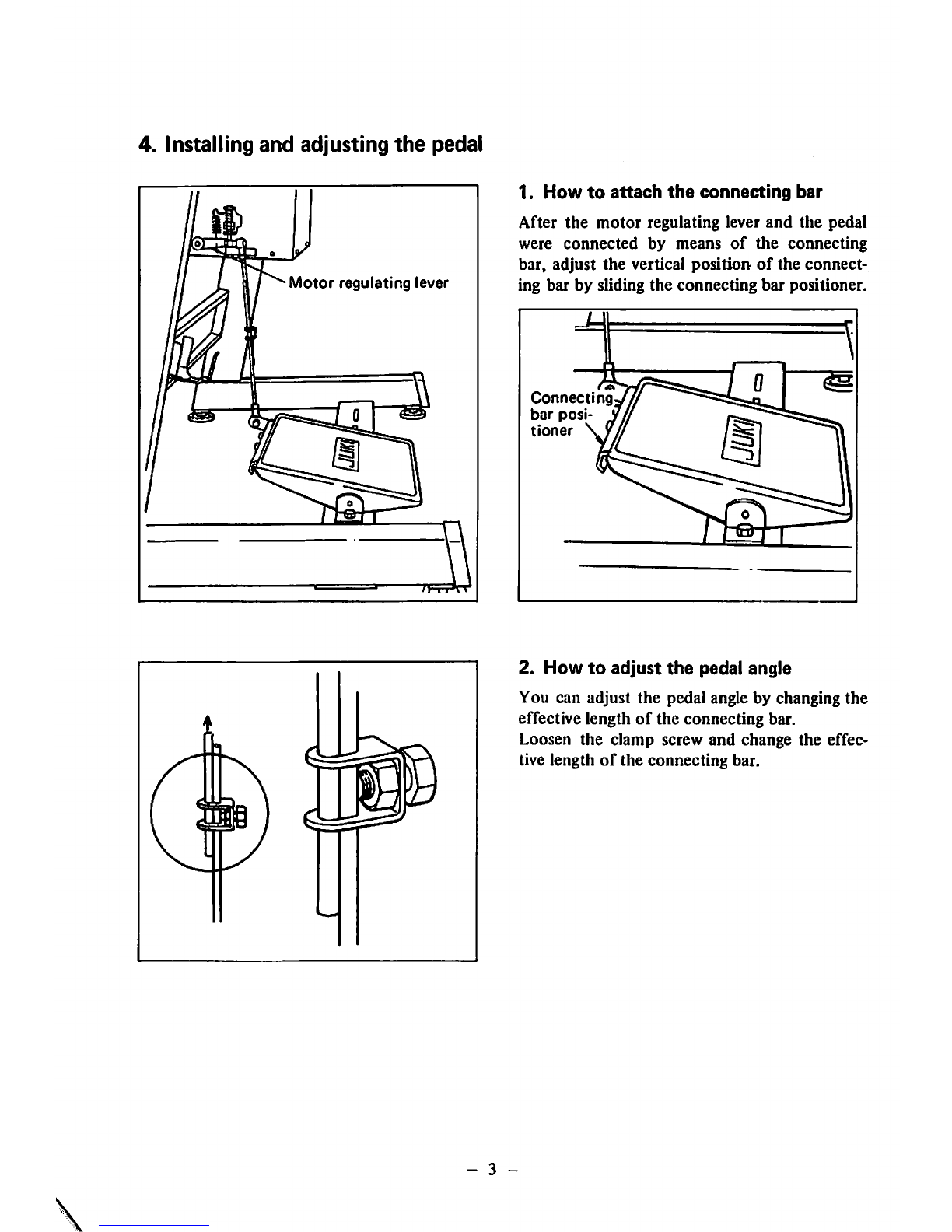
4. Installing and adjusting the pedal 3
5. Installing the synchronizer 4
6. Connecting the cords 5
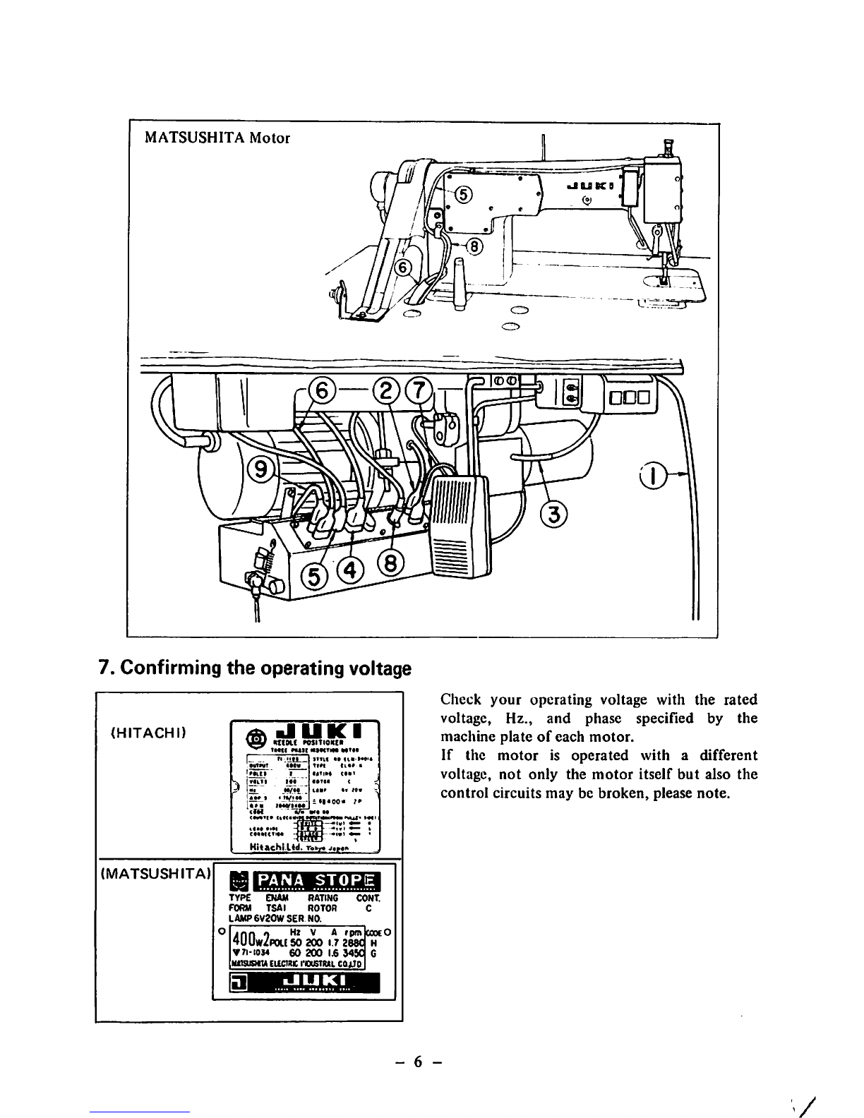
7. Confirming the operating voltage 6
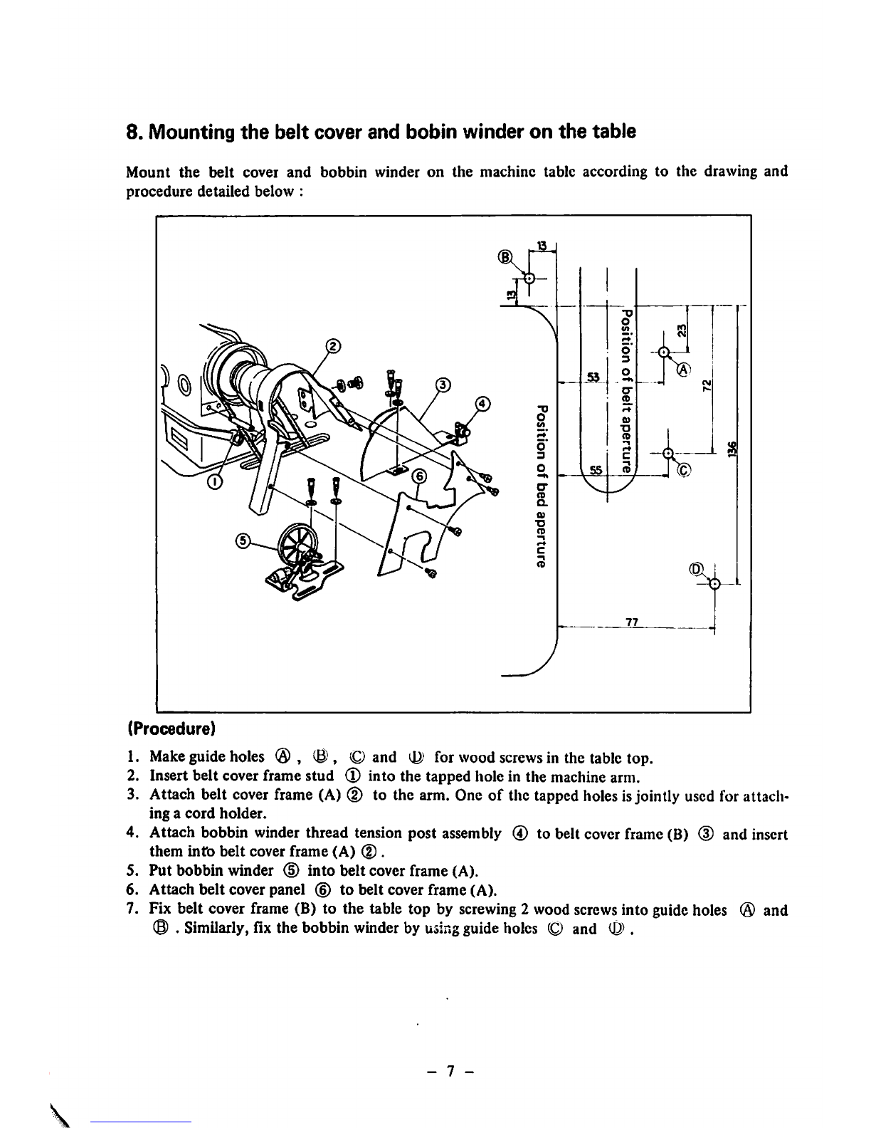
8. Mounting the belt cover and bobbin winder on the table 7
II. HOW TO
OPERATE
THE
MACHINE
8
1.
General
instruction
8
2.
Lubrication
and
amount
of
oil 9
3.
Checking
the pedalaction 10
4. How to operate the pedal 11
5. Adjusting the pedalpressureand stroke 12
6. Automatic count-back stitching 13
7.
Passing
the needlethread 14
8.
Bobbin
thread
15
9.
Adjusting
the threadtension 16
10. Attaching the needle 17
11. Presser
foot
18
12. Stitchlengthadjustment 19
13.
Reverse
stitchingby
using
the
reverse
feedcontrol
lever
19
HI. ADJUSTMENT 20
1.
Feed
mechanism 20
2. Replacingthe sewinghook 22
3. Sewinghook position related to the needle 23
4. Heightof the presserbar 24
5. Thread take-upaction 25
6. Returningpressureof the
reverse
feedcontrol lever 25
7.
Adjusting
the
needle
stop
position
after
thread
trimming
26
8.
Sharpening
the counterknife 27
IV. HOWTO ADJUST THE WIPER 28
1.
Adjusting
the positionof the wiper 28
2.
Adjust
the
position
of the
wiper
magnet
28
V. HOW TO USE AND ADJUST
THE
SWITCH-BACK BUTTON 29
1. Formingthe
switch-back
stitches 29
2. Adjustingthe position of the switch-backlever 29
3. Adjustingthe reversestitch length 30
VI.
AUTOMATIC
PRESSER
FOOT
LIFTER
(AK-2)
30
1. How to operate AK-2 30
2. Adjusting the presserlifter stroke 30
VII.
TROUBLES
AND
CORRECTIVE
MEASURE 31
VIII.
DIAGRAM
SHOWING
METHOD
OF
ASSEMBLING
TABLE
35
IX. DIMENSIONAL DIAGRAM OF THE TABLE (TOP SURFACE) 36
From the library of: Superior Sewing Machine & Supply LLC

I.
INSTALLATION
1.
Attaching
the
thread
stand
to
the
table
Assemble the thread stand and set it up on the machine table by using the installation holes in the
table
as
illustrated.
Do not tighten the clamping nut too much. When power source issupplied by the overhead wires,
pass the power supply cord through the spool rest rod.
2. Installing
the
oil reservoir
oi
Rubber
cushion
j-vf-r
reservoir
Operator
side
Hinge
side
Install
the
oil
reservoir
in
such
a
manner
that
it
is supported by the 4 corners of an opening in
the
table.
1. Nail in the 2 felt pads of 4 mm (5/32")
thick
to
the
2
corners
near
the
operator.
2. Nail in the 2 felt pads of 6 mm (15/64")
thick
to the remaining 2
corners
(hinged
side).
3. Place
the
oil reservoir on the
felt
pads.
4.
Insert
the
rubber
cushions
into
4
corners
by
your
finger.
5.
Put
the
round
felt
pads
to 4
rubber
cush
ions.
- 1 -
From the library of: Superior Sewing Machine & Supply LLC

3.
Motor
pulley
and
belt
You
must
use the M-typc V-belt.
The
under
mentioned table indicate tlie maximum sewing speeds related to tlie
motor
pulley and
the length of belts. The elTective diameter
of
the
motor
pulley is obtained by deducting 5 mm
(13/64")
from
the
outer
diameter.
Ou
ler
dia
meter
of
motor
pulley
Motor
pulley
Sewing
speed
Belt
Belt
Part
No.
50Hz
60Hz
length
Part
No.
125
mm
MTS-P01200AO
5,060
s.p.m.
44"
MTJ-VM004400
115
MTS-POl
100
AO
4,630
105
MTS-POIOOOAO
4,250
5,040
s.p.m.
100
MTS-P00950AO
4,000
4,780
43"
MTJ-VM004300
95
MTS-P00900A0
3,820
4,540
90
MTS-P00850A0
3,610
4,320
85
MTS-P00800A0
3,390
4,000
80
MTS-P00750A0
3,160
3,790
42"
MTJ-VM004200
75
MTS-P00700A0
2,950
3,520
70
MTS-P00650A0
2,740
3,260
(Note)
The
center
hole
on
the
motor
pulley
is
tapered,
and
the
normal
pulleys
commercially
avail
able
in
the
market
can
not
be
used
for
these
machines.
If
the
belt
is
too
long,
the
connecting
rod
may
not
work
smoothly.
(How
to
install
the
pulley)
Remove
pulley
cover 0
and
put
the
pulley
into
the
motor
shaft
by aligning the key way
with
the
key
of
the
shaft.
Tighten
pulley
nut
(D and fix it in position by set screw (3).
To remove the
motor
pulley, take
out
the
pulley cover and reverse the above mentioned
procedure
for installation.
- 2 -
From the library of: Superior Sewing Machine & Supply LLC

4. Installing
and
adjusting
the
pedal
Motor
regulating
lever
1.
How
to
attach
the
connecting
bar
After
the
motor
regulating lever
and
the
pedal
were
connected
by means
of
the
connecting
bar,
adjust
the
vertical
position
of
the
connect
ing bar by sliding
the
connecting
bar
positioner.
Connecting
bar
posi
tioner
2.
How
to
adjust
the
pedal angle
You can adjust
the
pedal angle by changing
the
effective length
of
the connecting bar.
Loosen
the
clamp
screw
and
change
the
effec
tive length
of
the
connecting
bar.
- 3 -
From the library of: Superior Sewing Machine & Supply LLC

5.
Installing
the
synchronizer
The necessary instruction for installation is indicated on the packing case on both of
"MATSUSHITA"
and
"HITACHI"
motors.
(CAUTIONS)
Support
rod
Nylon
clamper
Cord
\\\
\\ \
Stater
Magnet
Rotor
Printed
circuit
board
"MATSUSHITA"
motors
Screw
the
support
rod
into
the
threaded
hole
located on
the
right looking from
the
hand-
wheel
side
and
fix
it
with
a
lock
nut.
Fix
the
cord
onto
the
support
rod
by
means
of
the
nylon
clamper
so
that
it does
not
contact
with
the
V-belt.
"HITACHI"
motors
Be
careful
not
to
allow
the
rotor
and
the
stater
to
contact
with
each
other.
The
clearance
between
the
printed
circuit
board
cover
and
the
rotor
magnet
is 0.S
to
1.5
mm. Pass
the
cord
through
the
inside
of
the
synchronizer
cover
and
fix it
with
the
cord
clamp so
that
it does
not
contact
with the V-
belt.
- 4 -
1/
From the library of: Superior Sewing Machine & Supply LLC

6.
Connecting
the
cords
Before starting to connect the cords, make sure
that
the power source is
cutout.
Connect each cord
with care not to let it touch the motor pulley, V-belt or any other moving parts.
While you are connecting each plug, make sure that the plug is firmly secured in the receptacle by
trying
to
pull
it lightly.
(1) is the
power
supply
cord.
(2) is the cord for the magnetic clutch brake which is pre-connccted with 4-pole connector (HITA
CHI)
or
3-pole
connector
(MATSUSHITA).
(3) is the cord for controlling the knee lifter (2-pole connector). Only for AK-2.
(4) is the cord to the selector switch for controlling the count-back stitching (with 3-pole con
nector for HITACHI, 6-pole connector for MATSUSHITA).
(5) is the cord to the wiperand the control leverfor switch-backstitching (with 6-pole connector).
Pass the cord through the opposite side
of
the motor pulley via the hook beneath the table and
plug
in.
(6) is the cord for driving the thread trimmer solenoid and the automatic reverse feed solenoid,
(with
4-pole
connector).
(7)is the cord to
drive
the
solenoid
for the automatic lifter (with 4-pole connector). Only for
AK-2.
(8)is the cord to the synchronizer, (with
12-poIc
connector for
HITACHI
and 8-poleconnector for
MATSUSHITA).
(9) is the pre-connected cord to the controller. (3-pole connector).
(HITACH
Motor)
- 5 -
From the library of: Superior Sewing Machine & Supply LLC

MATSUSHITA
Motor
7. Confirming
the
operating voltage
(HITACHI)
(MATSUSHITA)
HlOchi.Ud.
Totx
j.Mi
PANA
STORE
TYPE ENAM RATING CONT.
FORM TSAI ROTOR C
LAWP6V20WSER
NO.
jnn
0 V A
rptnlcoocO
4UUw/P0US0 200 17 2e8C H
•
n-i034
60
200
Ij6
34S0
G
imsusTO
Eiicwic
rcusTittL
cajjo
•JUKI
>JUKB
I®®
Clieck
your
operating voltage with the
rated
voltage,
Hz.,
and
phase
specified
by
the
machine
plate
of
each
motor.
If the
motor
is
operated
with
a
different
voltage,
not
only
the
motor
itself
but
also
the
control
circuits
may
be
broken,
please
note.
- 6 -
V
From the library of: Superior Sewing Machine & Supply LLC

8. Mounting
the
belt
cover
and
bobin
winder
on
the
table
Mount
the
belt
cover
and
bobbin
winder
on
the
machine
table
according
to
the
drawing
and
procedure
detailed
below
:
(Procedure)
1.
Make
guide
holes
® ® , O and for
wood
screws
in the
table
top.
2. Insert belt coverframestud
(T)
into the tapped hole in the machinearm.
3. Attach belt coverframe (A) (D to the arm. One of the tappedholesisjointly usedfor attach
ing a
cord
holder.
4. Attach bobbin winder thread tension post assembly ® to belt cover frame (B) (D and insert
them
intb
belt cover frame (A)
(D.
5. Put bobbin winder (D into belt cover frame (A).
6.
Attach
belt
cover
panel
(6)
to
belt
cover
frame
(A).
7. Fix belt cover frame (B) to the table top by screwing2 wood screwsinto guide holes ® and
(8)
.Similarly, fix the bobbinwinderby
using
guideholes (Q and .
- 7 -
From the library of: Superior Sewing Machine & Supply LLC

II.
HOW
TO
OPERATE
THE
MACHINE
1.
General
instruction
After the machine has been set up, bring down the needle by rotating the handwheel with
your
hand,
switch
on
the
machine
on
trial
and
check
that
the
motor
rotates
in
the
correct
direction
by
watching
the
rotation
of
the handwheel.
The
handwheel
must
rotate
counterclockwise watching
from
the
open
side
of
the
handwheel.
If you fail to judge it, you can repeat to switch on and off the machine until the direction is found,
o
Clean
up
the
installed
machine.
o Before starting to operate the machine, read through the separate INSTRUCTION BOOK,
o Do
not
drive
the
machine
before
the
oil
reservoir
is filled
with
the
lubricating
oil.
o Do
not
replace
the
motor
pulley with alarger
one
within first 1
month.
You may operate the machine at a higher speed depending on the necessity
of
sewing works
and operator's ability after the first 1 montli has passed,
o Keep away
from
the
needle
dropping
place
when
you switch
the
machine
on.
o Do
not
fail to
switch
off
the
machine
before
you
tilt
the
machine
head
backwards
for
lubrica
tion or cleaning or removing
the
V-belt.
(If you mistakenly tread on the pedal, the motor puUeywill be stopped immediately by means
of
the built-in safety device in the case of
"HITACHI"
motor
assembly.)
o Whan
you
move
the
machine
to
other
places, do
not
hold it with
the
cover located on
the
rear
of
the
handwheel.
o Even if you tread on the pedal backwards (heel-down) immediately after the machine is switch
ed on or
the
thread
is trimmed,
the
needle
would
not
come
down
or
the
thread
trimmer
would
not work. Such thread trimming motion is performed only after the pedal has been trod once
forwards
(toc-down).
- 8
From the library of: Superior Sewing Machine & Supply LLC

Oil
sight
window
As long as the oil reservoir is properly filled up
with the lubricating oil, you will see the oil
splashing
on
the
internal
surface
of
the
oU sight
window
while
the
machine
is running. Since
the
oil sight
window
is used
only
to
check
if
the
lubricating oil is flowing or
not,
you
do
not
have to
worry
about
the
amount
of
oil
appear
ing in it.
(Notes)
1. As
soon
as
lubricating
oil
has
become
dirty,
renew
the
oil.
It
can
be
drained
by
removing
the
oil
drain
cap
screw.
2. In
order
to
thoroughly
lubricate
the
machine,
provide
it
with
an
idle
run
for
about
10
minutes
at
asewing
speed
of
3,000
to
3,500
s.p.m.
before
using a newly installed
machine
or
a
machine
which
has
not
been
operated
for
along
period
of
time.
2.
Lubrication
and
amount
of
oil
HIGH
mark
Oil
reservoir
LOW
mark
Before driving
the
machine,
fill
the
oil reservoir
with
JUKI
New Defrix Oil No. 1 up to
"HIGH"
level.
Take
care
not
to
allow
the
oil
level
to
come down below the "LOW" mark during
operation.
- 9 -
From the library of: Superior Sewing Machine & Supply LLC

Oil
adjusting
pin
Mark
r\
Oil
amount
gets
less
Crank
Mark
Crank
amount
gets
more
I I
II
Adjustment
of
oil
amount
fed
to
the
face
plate
components-
When adjusting the
amount
of
lubricating oil
flowing
into
the face plate components such as
the
thread
take-up
and
needle
bar
crank,
remove
the
face
plate
and
the
arm
oil
shield
and
rotate
the oil adjusting pin which is
located
on
the
top
end
of
the
main
shaft.
To minimize the oil flow, bring the
dot
mark
on the
adjusting
pin close to
the
crank.
To ma.\imize it, bring the
dot
mark to the far
side
of
the
crank.
(Note)
After this adjustment, let
the
machine run and confirm
the
result of adjustment.
Oil
regulating
valve
Adjustment
of
oil
amount
fed
to
the
sewing
hook:
Adjust it by
means
of
the
oil adjusting screw
which
is
located
on
the
hook
driving
shaft
from
bushing.
Amount
of
flowing oil is increased by
turning clockwise and decreased by turning
counterclockwise.
More
3.
Checking
the
pedal
action
Firstly, check your machine without passing the threads.
Switch on the machine,and the needle will be held at it's highest position without fail.
Even
the
needle
staying
at a
lower
position
will
be
brought
upand
held
at the
highest
position
by switching on the machine.
-
10
-
From the library of: Superior Sewing Machine & Supply LLC

4.
How
to
operate
the
pedal
As the following illustration shows, the pedal
of
this model is operated in 4 stages.
®
Place
your feet gentlyon the pedalat the stop position.
(The needle is held at the lowest position).
(D Tread on the pedal
lightly
forwards
(toe-down), and the
machine
starts to rotate at a low
speed.
(D Tread on the pedal further forwards (toe-down), and the machine will increase it's speed
gradually and attain the maximum speed when it has been
trod
down fully. However, when the
switch for the counter-back stitching is turned on, the machine will attain it's maximum sewing
speed only
after
the count-back stitch has been formed, even though you tread on the pedal
fully.
High
speed
Low
speed
Stop
(needle
down)
Thread
trimming
o You can obtain the normal performance of thread
trimming
by treading on the pedal back
wards (heel-down) directly from the high or low speed position,
o You can tread back the pedal to the neutral position immediately after the machine has started
to perform the thread trimming action.
The thread
trimming
action is automatically completed and youdo not needto keepthe
pedal
at the thread trimming position any longer,
o
When
the machinestops, the needle will be held at the lower position,
o
When
you want to bringup the
needle,
threadon the pedalfully
backwards
(heel-down)
once.
Then, the machine will perform a thread trimmingaction and willbringup the needleand hold
at
it's
highest position.
(Note)
Insome
cases,
the
machine
with
"MATSUSHITA"
motor,doesnot start to run immediately after a
thread
trimming
action
was
made
even
thoughthe
pedal
istrod
forwards
(toe-down).
Thisis
simply
because
the
machine
is
locked
by the safety
device
built in the motor
assembly,
in sucha
case,
tread on the pedal back to the neutral position once and tread on it again forward to drive the
machine.
In the
case
of the
machine
with
"HITACHI"
motor,suchsafety
device
is
automatically
released
after thread trimming action has been completed.
-
11
-
From the library of: Superior Sewing Machine & Supply LLC

5. Adjusting
the
pedal pressure and stroke
(MATSUSHITA)
Adjustment
grooves
Adjustment
nut
of
the
backward
pressure
spring.
C?
(MATSUSHITA)
Motor
regulating
lever
(HITACHI)
I Pedalpressure
^spring
(HITACHI)
Connecting
rod
(u
Adjustment
of
the
forward
pressure
Adjust the forward pressure by changing
the
position
of
the
spring.
"HITACHI"
motor:
The
pressure is
reduced
by moving tiie spring to
the
left
and
is increased to
the
right.
"MATSUSHITA"
motor:
The
pressure is reduced by moving the spring
to the right
and
is increased to
the
left.
Adjustment
of
the
backward pressure
"HITACHI"
motor;
The backward pressure can be adjusted by
means of the adjustment nut of the backward
pressure spring. The pressure is increased by
tightening the springand reduced by loosening.
Adjustment
of
the
pedal
stroke
The pedal stroke can be adjusted by changing
the
connection
of
the
upper
connecting rod
with the
motor
regulating lever.
"HITACHI"
motor:
The
stroke is reduced by connecting
the
rod
with
the
left
hand
side
of
the
lever
and
in
creased by the right
hand
side.
"MATSUSHITA"
motor:
The
stroke is reduced by connecting the rod
with the right hand
.side
of the lever and is
increased by
the
left
hand
side.
-
12
-
From the library of: Superior Sewing Machine & Supply LLC

6. Automatic count-back stitching
You
can
form
the
count-back
stitches
at the start and/or the end of a
seam
line
automatically
without
operation
of
the feed
control
lever or switch-back lever.
Count-back
stitch
at
the
start.
Count-back
stitch
at
the
end.
BACK
TAG SW.
START
0FF|^^l6iA
END(»*')
)
OFF^^-SiT
•JUKI
Selector
switch
for
forming
a
count-
back
stitch
at
the
start
of
a
seam
line.
Selector
switch
for
forming
a
count-
back
stitch
at
the
end
of
a
seam
line.
J
13
(T)
You can preset the machine to form the
count-back
stitches at
the
start
and/or
the
end
of
the
seam
line by
means
of
the
se
lector
switches.
(D If the number
of
count-back stitch is
not
enough for your sewing purpose, turn
off
the selector switch and produce the neces
sary length of reverse stitches manually by
making us
of
the
reverse feed
control
lever
or
the
switch-back
lever.
(3) When the selector switch for
"Start"
is
turned
on,
you
can
let
the
machine
to
automatically
trim
off
the
thread
immedi
ately by treading on the pedal backwards
before or after forming the count-back
stitch
at
the
start
of
a
seam
line.
Even
tiiough you tread on the pedal for thread
trimming while the count-back
stitch
is
being formed, the thread trimming action
will not be performed prior to the forma
tion
of
the
said
count-back
stitch.
® When the selector switch for
"End"
is
turned on, the thread trimming action will
be
performed
after
the
count-back
stitch
has
been
formed
at
the
end
of
a
seam
line.
If
you tread on the pedal for thread trimming
while the machine is forming a count-back
stitch at the end
of
a
.seam
line, the machine
will trim off the thread after completing the
said
count-back
stitch.
(Note)
When the selector switch for the automatic count-back stitching is not used (with a
HITACHI
motor): Disconnect the swjtch from the motor control box.
When
it is
used,
insert
a
connector
which
is
wired
as
illustrated
below
intothe
position
of 3-p
plug
( 4 ,
Fig.
paragraph
5)on the motorcontrolbox.
(Option.
PartNo.
D6010555DA0)
A
O
o
o
From the library of: Superior Sewing Machine & Supply LLC

7. Passing
the
needle
thread
o ir the machine stops leaving the needle at a lower position, tread on the pedal backwards for
performing an idle thread trimming before passing the needle thread.
Then,
the
needle will go up
and
stay
at
the
highest
position,
o Pass the needle thread in the
order
from ® to ® as shown in the illustration.
I
-
14
-
From the library of: Superior Sewing Machine & Supply LLC

8.
Bobbin
thread
Bobbin
case
Adjustment
screw
Tension
screw
Hook
Thread
tension
post
bracket
—Thread
hole
Thread
passing
hole
-
15
Inserting
and
removing
the
bobbin
case:
1. Bring up
the
needle to its highest
position
by
manually
rotating
the
handwheel.
2.
Tilt
the
machine
head
back
and
allow
it
to
rest
on
the
rubber
pads
attached
to
the
table.
3.
Lift
up
the
bobbin
case
latch
and
take
out
the
bobbin
case.
Bobbin will
not
fall
down
as long as the
latch
is
lifted.
4.
To
insert
the
bobbin
case, fully
insert
it
into
tiic
hook
shaft
so
that
the
nose
of
the
bobbin case rests in tlic
hook
groove
and
close
the
latch.
Winding
the
bobbin:
1.
Thread
the
bobbin
winder
in
the
order
as
illustrated
and
wind
the
thread
end
several
times
round
the
bobbin.
2. Push
down
the
bobbin
trip latch to let
the
bobbin
winder pulley
touch
the
belt.
3. Adjust the winding adjustment screw so
that
the
thread
is
wound
round
the
bobbin
for
about
80 per
cent
of
its capacity.
4. When the bobbin is wound unevenly,
correct it by moving the thread tension post
bracket.
Tighten the screw for increasing the thread
length
to be
wound
and
loosen
for
reduce.
5. As soon as the
bobbin
in filled, the bobbin
winder will automatically stop.
(Note)
In order not to wound
the
bobbin
too
tight
with
a
synthetic
thread,
adjust
the
tension
screw so
that
the
thread
is lightly
drawn
from
thr
thread
tension
post
socket,
inserting
the
bobbin
into
the
bobbin
case:
1.
Take
the
bobbin
in
your
hand
so
that
the thread is directed clockwise and place it
into
the
bobbin
case.
2. Take the thread in your
fingers
and pull up
toward
the
slot
in
the
bobbin
case.
3. Pull the thread, and it will pass through the
thread tension spring.
""Make
sure that the bobbin spins in the
bobbin
case
in
the
direction
indicated
with
the
arrow
when
the
thread
is
drawn.
From the library of: Superior Sewing Machine & Supply LLC

9. Adjusting
the
thread
tension
Decreased
Decreased
Moving
range
V\S—Increased
Thread
tension
No.
1
Thread
tension
bar
Increased
Thread
tension
No.
2
thread
take-up
spring
Tension
bracket
set
screw
Thread
tension
bar
set
screw
Thread
tension
socket
Thread
take-up
spring
(Note)
When using a thin cotton or synthetic thread,
excessive
tension
or
stroke.
Otherwise, stitch may be skipped at the end of
Needle
thread
tension:
Needle thread tension is adjusted by the thread
tension
nuts
No. 1
and
No, 2
thread
tension
is
increased by a clockwise turn and reduced by a
counter-clockwise
turn,
o
Thread
tension
No.
1.
The length of needle thread remaining in the
needle
after
thread trimming becomes
short
when
the
thread
tension
nut
No. 1 is
tight
ened, and vice versa. Tighten the tension
nut
when
a
thin
thread
like
synthetic
thread
is
used
and
loosen
it
when
a
thick
thread
is
used.
o
Thread
tension
No.
2
Adjust the thread tension nut No. 2 so that
the
needle
and
bobbin
threads
are
inter-
looped in the middle of the material. Do not
excessively reduce the thread tension when
sewing with a synthetic thread, or the
thread may be broken at the start of sewing.
Thread
take-up
spring
Adjust the thread take-up spring for the follow
ing
standard:
Thread
Thread
No.
Stroke
Tension
Cotton
#40
or
less
7
to
10
mm
(9/32"
to 25/64") 20 to 35g
Cotton
#50
or
more
6
to
9
mm
(15/64" to 23/64") 15 to 30g
Synthetic
6
to
9
mm
(15/64"
to 23/64") 7 to 20g
o To change the stroke of the thread take-up
spring, loosen the screw of the thread
tension post socket and turn the thread
tension post in either direction,
o To change the tension of the thread
tate-up
spring, loosen the screw of the thread
tension post socket, remove the thread
tension post and adjust the tension after
loosening
the
set
screw.
Tension is increased by turning the thread
tension post in the clockwise direction, and
vice
versa.
take
care not to provide
the
take-up spring with an
sewing and the threads will not be trimmed.
-
16
-
From the library of: Superior Sewing Machine & Supply LLC

Howto adjust the thread length remaining in the needleafter thread trimming:
o In order to prevent the needle thread from slipping
off
and produce neat stitch on the bottom
. face of the materialat the start of
sewing,
a proper lengthof needlethread must beleft in the
needle eye after thread trimming.
o The thread length is adjusted by the thread tension No. 1.
o It is possible to provide the thread trimmer with different timing of action to trim a synthetic
thread from that of cotton thread. Consult withour distributorsor agentsin your area for this
modification.
Increased
Adjusting
screw
Reduced
10.
Attaching
the
needle
Bobbin
thread
tension:
Bobbin
thread
tension can be adjusted by
tightening or loosening
the
tension screw
of
the
bobbin
case.
Turn
the
screw
clockwise
for
increasing and counterclockwise for reducing
the
bobbin
thread
tension.
Use
a proper size of
DB,\1
or DAxl needle according to the
material as listed below; thickness and
type
of
thread
and
Needle
Thread
Material
Cotlon
Synthetic
DB
X 1
#9
#80
#80
Fine
Georgette, nylon,
tetron
broadcloth
11
80-60
80-60
Light-weight Broadcloth, light-weight knits
14
60-50
60-50
General
cloth
Cotton
gabardine,
drill
16
0
1
o
50-30
Medium-weight Coatings
18
30-20
30-20
Heavy-weight
Denim
21
30-
8
Extra-heavy
Cantton,
canvas
22.23
8
Extra-heavy
Cantton,
canvas
DA
xl
8-9
80
80
Fine
Georgette, nylon,
tetron
broadcloth
11
60 60
Light-weight
Broadcloth,
fine
knits
14
50
50
General
cloth
Cotton
gabardine, drill
-
17
-
From the library of: Superior Sewing Machine & Supply LLC
Other manuals for DDL-555-4
1
Table of contents
Other JUKI Sewing Machine manuals

JUKI
JUKI LBH-1702 User manual

JUKI
JUKI PLK-J4040 User manual

JUKI
JUKI MB-1373 User manual

JUKI
JUKI MF-7700D Series User manual

JUKI
JUKI LG-158 User manual

JUKI
JUKI LZH-1290 User manual

JUKI
JUKI LZ-2290A Series User manual

JUKI
JUKI LU-2210N-6 User manual

JUKI
JUKI MO-623 User manual

JUKI
JUKI MH-481 User manual