JUKI DDL-8700A-7 User manual

i
ENGLISH
INSTRUCTION MANUAL
DDL-8700A-7

i
CONTENTS
!. SPECIFICATIONS ..................................................................................... 1
@. SET-UP...................................................................................................... 3
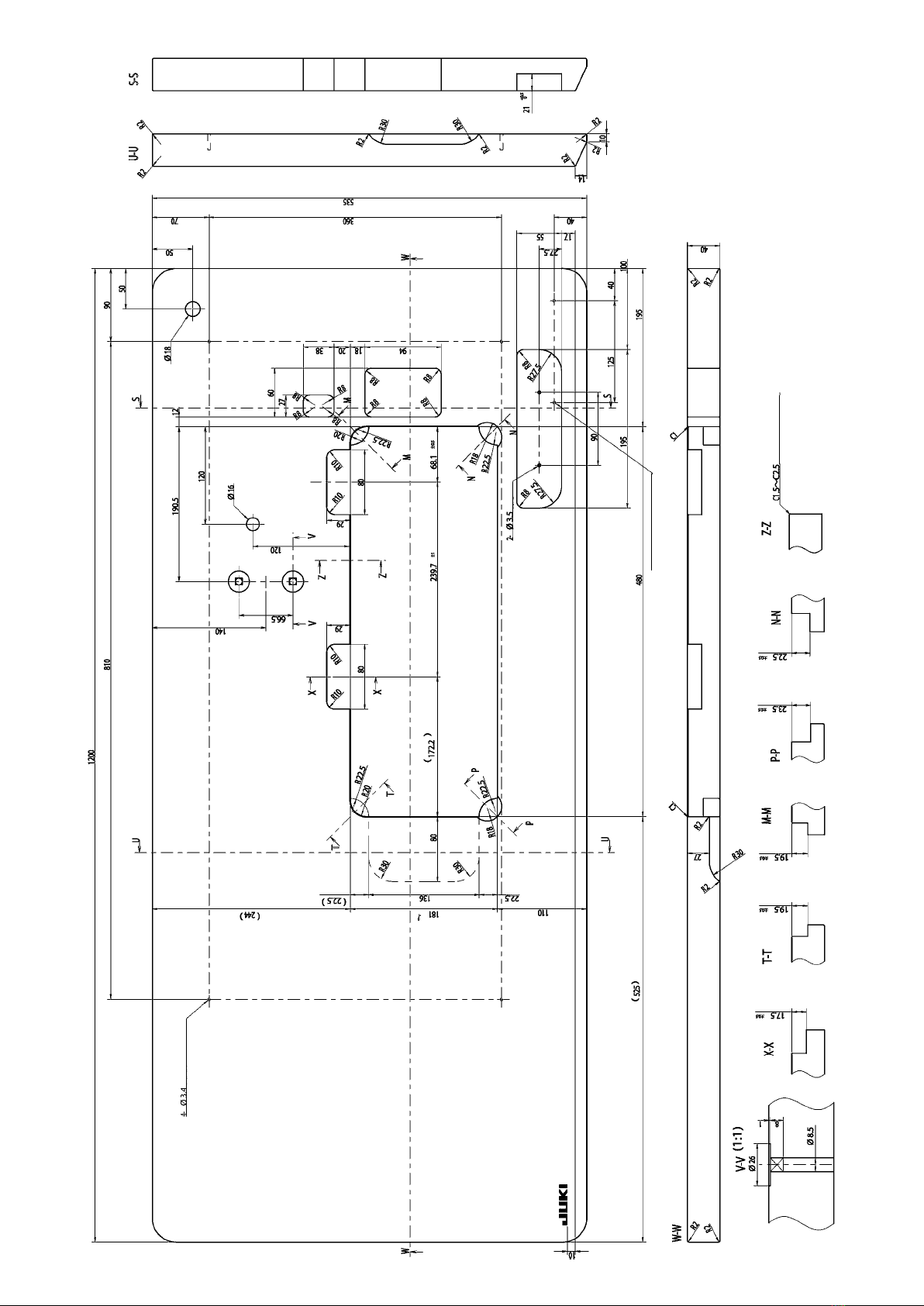
1. Installation.................................................................................................................. 3
2. Installing the pedal sensor ....................................................................................... 4
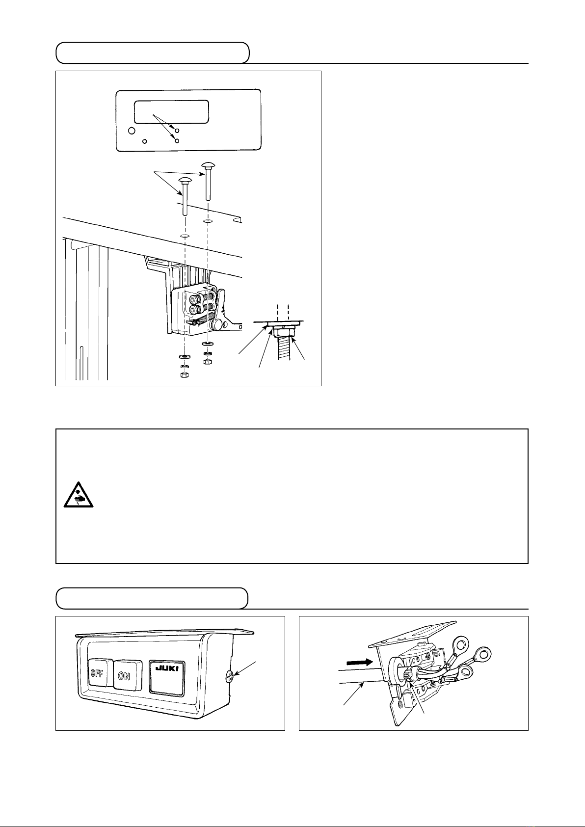
3. Installing the power switch....................................................................................... 4
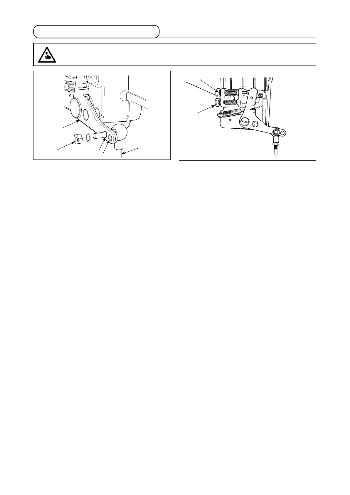
4. Attaching the connecting rod ................................................................................... 6
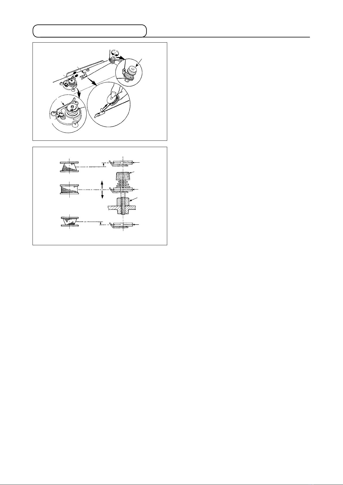
5. Winding the bobbin thread ....................................................................................... 7
6. Adjusting the height of the knee lifter ..................................................................... 8
7. Installing the thread stand ........................................................................................ 8
8. Lubrication ................................................................................................................. 9
9. Adjusting the amount of oil (oil splashes) .............................................................. 9
10. Attaching the needle...............................................................................................11
11. Setting the bobbin into the bobbin case ............................................................. 12
12. Adjusting the stitch length.................................................................................... 12
13. Presser foot pressure............................................................................................ 12
14. Hand lifter ............................................................................................................... 12
15. Adjusting the height of the presser bar............................................................... 13
16. Threading the machine head ................................................................................ 13
17. Thread tension ....................................................................................................... 14
18. Thread take-up spring ........................................................................................... 14
19. Adjusting the thread take-up stroke .................................................................... 14
20. Needle-to-hook relationship ................................................................................. 15
21. Height of the feed dog........................................................................................... 15
22. Tilt of the feed dog................................................................................................. 16
23. Adjusting the feed timing...................................................................................... 16
24. Cunter knife............................................................................................................ 17
25. Pedal pressure and pedal stroke ......................................................................... 17
26. Adjustment of the pedal ........................................................................................ 18
#. FOR THE OPERATOR ............................................................................ 19
1. Operating procedure of the sewing machine........................................................ 19
2. Built-in panel of the machine head ........................................................................ 21
3. Operating procedure of the sewing pattern .......................................................... 22
4. One-touch setting .................................................................................................... 24
5. Production support function .................................................................................. 25
6. Setting of functions ................................................................................................. 28
7. Function setting list................................................................................................. 29
8. Detailed explanation of selection of functions ..................................................... 33
9. Automatic compensation of neutral point of the pedal sensor........................... 43
10. Selection of the pedal specications................................................................... 43

ii
11. Setting of the auto lifter function ......................................................................... 44
12. Selecting procedure of the key-lock function..................................................... 45
13. Removing the rear cover....................................................................................... 46
14. Connection of the pedal of standing-work machine .......................................... 48
15. External input / output connector ........................................................................ 48
16. Connection of the material end sensor ............................................................... 49
17. Initialization of the setting data ............................................................................ 50
$. MAINTENANCE ...................................................................................... 51
1. Replacing the fuse................................................................................................... 51
2. Adjusting the machine head ................................................................................... 52
3. Connector layout drawing ...................................................................................... 53
4. Error codes............................................................................................................... 54

– 1 –
S :
Medium-weight materials
H : Heavy-weight materials
DDL-8700AS-7 DDL-8700AH-7
Max. sewing speed 5,000 sti/min 4,000 sti/min
Thread trimming speed 300 sti/min 300 sti/min
Stitch length 4mm 5mm
Presser foot lift
(by knee lifter) 13 mm 13 mm
Needle *1 DB x 1 (#14) #9 to 18 DB x 1 (#21) #20 to 23
Lubricating oil JUKI MACHINE OIL #7 JUKI MACHINE OIL #7
• The sewing speed will vary depending on the sewing conditions.
• The sewing speed preset at the time of shipping ...... AS-7 : 4,000sti/min.
...... AH-7 : 3,500sti/min.
*1 : Needle used depends on the destination.
!. SPECIFICATIONS
Supply voltage Single phase 100 to 120V 3-phase 200 to 240V Single phase 220 to 240V
Frequency 50Hz/60Hz 50Hz/60Hz 50Hz/60Hz
Operating environ-
ment
Temperature : 5 to 35˚C
Humidity 35 - 85 % or less
Temperature : 5 to 35˚C
Humidity 35 - 85 % or less
Temperature : 5 to 35˚C
Humidity 35 - 85 % or less
Input 210VA 210VA 210VA
DDL-8700A - 7
Noise
- Equivalent continuous emission sound pressure level (LpA) at the workstation :
A-weighted value of 79.5 dB; (Includes KpA = 2.5 dB); according to ISO 10821- C.6.2 -ISO
11204 GR2 at 4,000 sti/min.

– 2 –
DRAWING OF TABLE
bottom surface, depth 20
2-ø3.4 bottom surface, depth 10
depth 10
(Hinge side only)

– 3 –
1) Carry the sewing machine with two persons as
shown in the gure above.
(Caution) Do not hold the handwheel.
2) Do not put protruding articles such as the screw-
driver and the like at the location where the sew-
ing machine is placed.
3) The under cover should rest on the four cor-
ners of the machine table groove. Mount rubber
hinge seat 8 on the table and x it on the table
with a nail.
4) Fix two rubber seats 1on side A(operator’s side) using nails 2as illustrated above. Fix two cushion seats
3on side B(hinged side) using a rubber-based adhesive. Then place under cover 4 on the xed seats.
@. SET-UP
11
3
3
8
1
2
4
3
AB
1
2
4
3
AB
Needle bar side
!0
7
8
7
6
9
!2
!1
5) Fit knee lifter pressing rod 6. Fit hinge 7 into the opening in the machine bed, and t the machine head
to table rubber hinge 8before placing the machine head on cushions 9on the four corners.
6) Securely attach head support rod !0 to the table until it goes no further.
(Caution) Be sure to install the machine head support bar supplied with the unit.
7) Draw out cable !1 of the control box through cable draw-out hole !2 to route it to the underside of the
sewing machine table.
19.5mm
23mm
19.5mm
23.5mm
Control box side
1. Installation

– 4 –
1
1
2. Installing the pedal sensor
The explanation applies to the case the
pedal sensor is installed on the table for
the DDL-8700A-7.
1) Install the pedal sensor on the table
by means of mounting bolt asm. 1
supplied with the unit. At this time,
insert the nut and washer supplied
with the unit as accessories as shown
in the gure so that the control box is
securely xed.
2) After the completion of installation of
the pedal sensor on the table, place
the sewing machine head on the
table.
Spring
washer
Hexagonal
nat
1
Plain
washer
3. Installing the power switch
1) Remove screw 1on the side face of the power
switch cover to open the power switch cover.
2)
Pass AC input cord 2coming from the control box
through the rear face of the power switch. Bundle
the cord with cable clip band 3to secure it.
(Caution) Do not insert the power plug into the plug receptacle.
2
3
WARNING :
• To protect against personal injury resulting from abrupt start of the sewing machine, be sure to
turn the power OFF, unplug the machine and wait for ve minutes or more before installing the
pedal sensor.
•To prevent damage of device caused by maloperation and wrong specifications, be sure to
connect all the corresponding connectors to the specied places. (If any of the connectors is
inserted into a wrong connector, not only the device corresponding to the connector can break
but also it can start abruptly, inviting the risk of personal injury.)
•To prevent personal injury caused by maloperation, be sure to lock the connector with lock.
• As for the details of handling respective devices, read carefully the Instruction Manuals supplied
with the devices before handling the devices.

– 5 –
6) Connect the power cord to the power plug.
As shown in the gure, connect the white and black
(and red) wires to the power supply side and the
green/yellow one to the grounding side.
(Caution) 1. Be sure to prepare the power plug 3
which conforms to the safety stan-
dard.
2. Be sure to connect the ground lead
(green/yellow) to the grounding side.
7) Check that the power switch is in the OFF state.
Then, insert the power plug coming from the power
switch into the plug receptacle.
(Caution) In prior to the connection of the power
plug, re-check the supply voltage speci-
cation indicated on the power box.
Power switch
AC cable
Pedal sensor cable
3) Securely x the terminals of the AC input cord
by tightening the screws at the specied loca-
tions.
4) Close the power switch cover. Tighten screw 1
on the side face of the power switch cover.
5) Firstly attach the staple supplied with the unit as
accessories to the cable. Then, hammer them
into the sewing machine table.
At this time, attach the staples at the locations
shown in the gure.
Staples
(large)
Cable draw-out
hole
Pedal sensor Staples (small)
Green/
Yellow
White
Black
3
WARNING :
1. Be sure to attach the ground wire (green/yellow) to the specied location (on the ground side).
2. Take care not to allow terminals to come in contact with each other.
3. When closing the power switch cover, take care not to allow the cord to be caught under it.
3ø 200V-240V
1ø 100V-120V
220V-240V
AC 200V-240V
Black
Red
White
Green / Yellow
(ground wire)
Black
White
Green / Yellow
(ground wire)
AC 100V-120V
AC 220V-240V
3ø 200V-240V
1ø 100V-120V
220V-240V
Green/
Yellow Red
White
Black

– 6 –
4. Attaching the connecting rod
1) Fix connecting rod 1to installing hole Bof
pedal lever 2with nut 3.
2) Installing connecting rod 1to installing hole A
will lengthen the pedal depressing stroke, and
the pedal operation at a medium speed will be
easier.
3) The pressure increases as you turn reverse de-
pressing regulator screw 4in, and decreases as
you turn the screw out.
(Caution) 1. If the screw is excessively loosened,
the spring will come off.
Loosen the screw to such an extent
that the top of the screw can be ob-
served from the case.
2. Whenever you have adjusted the
screw, be sure to secure the screw by
tightening metal nut 5to prevent the
screw from loosening.
WARNING :
To protect against possible personal injury due to abrupt start of the machine, be sure to start the
following work after turning the power off and a lapse of 5 minutes or more.
1
2
BA
3
4
5

– 7 –
1) Insert the bobbin deep into the bobbin winder
spindle 1until it will go no further.
2) Pass the bobbin thread pulled out from the
spool rested on the right side of the thread stand
following the order as shown in the gure on the
left. Then, wind clockwise the end of the bobbin
thread on the bobbin several times.
(In case of the aluminum bobbin, after winding
clockwise the end of the bobbin thread, wind
counterclockwise the thread coming from the
bobbin thread tension several times to wind the
bobbin thread with ease.)
3) Press the bobbin winder trip latch 2in the
direction of Aand start the sewing machine.
The bobbin rotates in the direction of Cand the
bobbin thread is wound up. The bobbin winder
spindle 1automatically as soon as the winding
is nished.
4) Remove the bobbin and cut the bobbin thread
with the thread cut retainer 3.
5) When adjusting the winding amount of the bob-
bin thread, loosen setscrew 4and move bobbin
winding lever 2to the direction of Aor B. Then
tighten setscrew 4.
To the direction of A: Decrease
To the direction of B: Increase
5. Winding the bobbin thread
6) In case that the bobbin thread is not wound evenly on the bobbin, remove the handwheel, loosen screw
5and adjust the height of bobbin thread tension 8.
• It is the standard that the center of the bobbin is as high as the center of thread tension disk 6.
• Adjust the position of thread tension disk 6to the direction of Dwhen the winding amount of the bobbin
thread on the lower part of the bobbin is excessive and to the direction Ewhen the winding amount of
the bobbin thread on the upper part of the bobbin is excessive.
After the adjustment, tighten screw 5.
7) To adjust the tension of the bobbin winder, turn the thread tension nut 7.
(Caution)
1. When winding the bobbin thread, start the winding in the state that the thread between the bobbin
and thread tension disk 6is tense.
2. When winding the bobbin thread in the state that sewing is not performed, remove the needle thread
from the thread path of thread take-up and remove the bobbin from the hook.
3. There is the possibility that the thread pulled out from the thread stand is loosened due to the inu-
ence (direction) of the wind and may be entangled in the handwheel. Be careful of the direction of
the wind.
D
E
B
3
1
6
7
6
5
6
A
C
8
4
2

– 8 –
1) The standard height of the presser foot lifted using the knee lifter is 10 mm.
2) You can adjust the presser foot lift up to 13 mm using knee lifter adjust screw 1.
3) When you have adjusted the presser foot lift to over 10 mm, be sure that the bottom end of needle bar
2in its lowest position does not hit presser foot 3.
1
2
3
WARNING :
Be sure to turn the power OFF before the following work in order to prevent personal injury due to
unintentional starting of the sewing machine.
6. Adjusting the height of the knee lifter
7. Installing the thread stand
2
1
1) Assemble the thread stand unit, and insert it in
the hole in the machine table.
2) Tighten nut 1.
3) For ceiling wiring, pass the power cord through
spool rest rod 2.

– 9 –
12
A
B
1) Before starting the sewing machine, ll oil pan
1with JUKI MACHINE OIL #7 up to HIGH mark
A.
2) When the oil level lowers below LOW mark B,
rell the oil pan with the specied oil.
3) When you operate the machine after lubrica-
tion, you will see splashing oil through oil sight
window 2if the lubrication is adequate.
4) Note that the amount of the splashing oil is un-
related to the amount of the lubricating oil.
1. When you use a new sewing machine or a sewing machine after an extended period of dis-
use, use the sewing machine after performing break-in at 2,000 sti/min or less.
2. For the oil for hook lubrication, purchase JUKI NEW DEFRIX OIL No. 1 (Part No. : MD-
FRX1600C0) or JUKI MACHINE OIL #7 (Part No. : MML007600CA).
3. Be sure to lubricate clean oil.
WARNING :
1. Do not connect the power plug until the lubrication has been completed so as to prevent
accidents due to abrupt start of the sewing machine,
2. To prevent the occurrence of an inammation or rash, immediately wash the related portions if
oil adheres to your eyes or other parts of your body.
3. If oil is mistakenly swallowed, diarrhea or vomitting may occur. Put oil in a place where children
cannot reach.
8. Lubrication
1 Amount of oil (oil splashes) conrmation paper 2 Position to conrm the amount of oil (oil splashes)
Closely t the paper against the wall
surface of the bed.
Oil splashes conrmation paper
3 - 10 mm
25 mm
70 mm
* When carrying out the procedure described below in 2, remove the slide plate and take extreme caution
not to allow your ngers to come in contact with the hook.
1) If the machine has not been sufciently warmed up for operation, make the machine run idle for approxi-
mately three minutes. (Moderate intermittent operation)
2) Place the amount of oil (oil spots) conrmation paper under the hook immediately after the machine
stops running.
3) Conrm the height of the oil surface in the oil reservoir is within the range between “HIGH” and “LOW”.
4) Conrmation of the amount of oil should be completed in ve seconds. (Check the period of time with a
watch.)
WARNING :
Be extremely careful about the operation of the machine since the amount of oil has to be checked
by turning the hook at a high speed.
9. Adjusting the amount of oil (oil splashes)
(1) Conrmation of the amount of oil in the hook

– 10 –
1) The amount of oil shown in the samples on the left
should be nely adjusted in accordance with sewing
processes.
Be careful not to excessively increase/decrease the
amount of oil in the hook. (If the amount of oil is too
small, the hook will be seized (the hook will be hot).
If the amount of oil is too much, the sewing product
may be stained with oil.)
2) Adjust the amount of oil in the hook so that the
oil amount (oil splashes) should not change while
checking the oil amount three times (on the three
sheets of paper).
Splashes of oil from the hook
* mm
Appropriate amount of oil (large)
Appropriate amount of oil (small)
1) Turning the oil amount adjustment screw attached
on the hook driving shaft front bushing in the “+”
direction (in direction A) will increase the amount of
oil (oil spots) in the hook, or in the “–” direction (in
direction B) will decrease it.
2) After the amount of oil in the hook has been prop-
erly adjusted with the oil amount adjustment screw,
make the sewing machine run idle for approximately
30 seconds to check the amount of oil in the hook.
A
B
(2) Adjusting the amount of oil (oil spots) in the hook
(3) Sample showing the appropriate amount of oil in the hook
* mm
Splashes of oil from the hook
1Amount of oil (oil splashes) conrmation paper
2 Position to conrm the amount of oil
(oil splashes)
Oil splashes
conrmation paper
25 mm
70 mm
(4) Conrmation of the amount of oil supplied to the face plate parts
* When carrying out the work described below in
2), remove the face plate and take extreme cau-
tion not to allow your ngers to come in contact
with the thread take-up lever.
1) If the machine has not been sufciently warmed
up for operation, make the machine run idle for
approximately three minutes. (Moderate inter-
mittent operation)
2) Place the amount of oil (oil spots) conrmation
paper under the hook immediately after the ma-
chine stops running.
3) Conrm the height of the oil surface in the oil
reservoir is within the range between “HIGH”
and “LOW”.
4) The time required for the conrmation of the
amount of oil (oil splashes) should be completed
in ten seconds. (Measure the period of time with
a watch.)
* mm
DDL-8700AS-7 1mm
DDL-8700AH-7
* mm
DDL-8700AS-7 2mm
DDL-8700AH-7 3mm

– 11 –
1) Adjust the amount of oil supplied to the thread
take-up and needle bar crank 2by turning ad-
just pin 1.
2) The minimum amount of oil is reached when
marker dot Ais brought close to needle bar
crank 2by turning the adjust pin in direction B.
3) The maximum amount of oil is reached when
marker dot Ais brought to the position just op-
posite from the needle bar crank by turning the
adjust pin in direction C.
minimum
maximum
1
2
A
B
C
1
(6) Sample showing the appropriate amount of oil supplied to the face plate parts
1) The state given in the gure shows the appropri-
ate amount of oil (oil splashes). It is necessary
to nely adjust the amount of oil in accordance
with the sewing processes. However, do not
excessively increase/decrease the amount of oil
in the hook. (If the amount of oil is too small, the
hook will be seized (the hook will be hot). If the
amount of oil is too much, the sewing product
may be stained with oil.)
2) Adjust the amount of oil in the hook so that the
oil amount (oil splashes) should not change
while checking the oil amount three times (on
the three sheets of paper).
Use the specied needle for the machine. Use the
proper needle in accordance with the thickness of
thread used and the kinds of the materials.
1) Turn the handwheel until the needle bar reaches
the highest point of its stroke.
2) Loosen screw 2, and hold needle 1with its
indented part Afacing exactly to the right in
direction B.
3) Insert the needle fully into the hole in the needle
bar in the direction of the arrow until the end of
hole is reached.
4) Securely tighten screw 2.
5) Check that long groove Cof the needle is facing exactly to the left in direction D.
(Caution) When polyester lament thread is used, if the indented part of the needle is tilted toward opera-
tor's side, the loop of thread becomes unstable. As a result, hangnail of thread or thread breakage may
occur. For the thread that such phenomenon is likely to occur, it is effective to attach the needle with its
indented part slightly slanting on the rear side.
1
2
C
DB
A
10. Attaching the needle
WARNING :
Be sure to turn the power OFF before the following work in order to prevent personal injury due to
unintentional starting of the sewing machine.
S
plashes of oil from the thread take-up lever
1 mm
Appropriate amount of oil (large)
Appropriate amount of oil (small)
2 mm
S
plashes of oil from the thread take-up lever
(5) Adjusting the amount of oil supplied to the face plate parts

– 12 –
1) Pass the thread through thread slit A, and
pull the thread in direction C. By so doing, the
thread will pass under the tension spring and
come out from notch B.
2) Check that the bobbin rotates in the direction of
the arrow when thread is pulled.
B
C
A
29 to 32 mm
11. Setting the bobbin into the bobbin case
12. Adjusting the stitch length
13. Presser foot pressure
14. Hand lifter
* The dial calibration is in millimeters.
1) Turn stitch length dial 1in the direction of the
arrow, and align the desired number to marker
dot Aon the machine arm.
1) Loosen nut 2. As you turn presser spring regu-
lator 1clockwise (in direction A), the presser
foot pressure will be increased.
2) As you turn the presser spring regulator counter-
clockwise (in direction B), the pressure will be
decreased.
3) After adjustment, tighten nut 2.
The standard value of the pressure regulating thumb
screw is 29 to 32 mm.
1) The presser foot is lifted by moving the lever
upward.
2) The presser foot is lowered by moving the lever
downward.
A
1
2
1
A
B

– 13 –
1) Loosen setscrew 1, and adjust the presser bar
height or the angle of the presser foot.
2) After adjustment, securely tighten the setscrew
1.
1
15. Adjusting the height of the presser bar
16. Threading the machine head
WARNING :
Be sure to turn the power OFF before the following work in order to prevent personal injury due to
unintentional starting of the sewing machine.
WARNING :
Be sure to turn the power OFF before the following work in order to prevent personal injury due to
unintentional starting of the sewing machine.

– 14 –
(1) Changing the stroke of thread take-up
spring 1
1) Loosen setscrew 2.
2) As you turn tension post 3clockwise (in direc-
tion A), the stroke of the thread take-up spring
will be increased.
3) As you turn the knob counterclockwise (in direc-
tion B), the stroke will be decreased.
(2) Changing the pressure of thread take-up
spring 1
1) Loosen setscrew 2,and remove tension post 3.
2) Loosen setscrew 4.
3) As you turn tension post 3clockwise (in direc-
tion A), the pressure will be increased.
4) As you turn the tension post counterclockwise (in
direction B), the pressure will be decreased.
1
2
3
4
5
1
B
A
1) When sewing heavy-weight materials, move
thread guide 1to the left (in direction A) to
increase the length of thread pulled out by the
thread take-up.
2) When sewing light-weight materials, move
thread guide 1to the right (in direction B) to
decrease the length of thread pulled out by the
thread take-up.
3) Normally, thread guide 1is positioned in a way
that marker line Cis aligned with the center of
the screw.
1
C
BA
(1) Adjusting the needle thread tension
1) The length of thread remaining at the needle
tip after thread trimming is shortened by turn-
ing tension regulating nut No. 1 1clockwise in
direction A.
2) It is lengthened by turning the nut counterclock-
wise in direction B.
3) The needle thread tension is increased by turn-
ing tension regulating nut No. 2 2clockwise in
direction C.
4) It is decreased by turning the nut counterclock-
wise in direction D.
(2) Adjusting the bobbin thread tension
1) The bobbin thread tension is increased by turn-
ing tension regulating screw 3clockwise in
direction E.
2) It is decreased by turning the screw counter-
clockwise in direction F.
A
B
C
D
EF
1
2
3
17. Thread tension
18. Thread take-up spring
19. Adjusting the thread take-up stroke
WARNING :
Be sure to turn the power OFF before the following work in order to prevent personal injury due to
unintentional starting of the sewing machine.

– 15 –
4) After making the adjustments mentioned in the above steps, align hook blade point 5with the center
of needle 4. Provide a clearance of 0.04 mm to 0.1 mm (DDL-8700AH-7 : 0.06 to 0.17mm) (reference
value) between the needle and the hook, then securely tighten setscrews in the hook.
If the clearance between the blade point of hook and the needle is smaller than the specied
value, the blade point of hook will be damaged. If the clearance is larger, stitch skipping will
result.
1
To adjust the height of the feed dog :
1Loosen screw 2of crank 1.
2Move the feed bar up or down to make adjust-
ment.
3Securely tighten screw 2.
If the clamping pressure is insufcient,
the motion of the forked portion be-
comes heavy.
(1) Adjust the timing between the needle and
the hook as follows :
1) Turn the handwheel to bright the needle bar
down to the lowest point of its stroke, and
loosen setscrew 1.
(Adjusting the needle bar height)
2) (For a DB needle) Align marker line Aon
needle bar 2with the bottom end of needle bar
lower bushing 3, then tighten setscrew 1.
(For a DA needle) Align marker line Con
needle bar 2with the bottom end of needle bar
lower bushing 3, then tighten setscrew 1.
(Adjusting position of the hook a)
3) (For a DB needle) Loosen the three hook
setscrews, turn the handwheel and align marker
line Bon ascending needle bar 2with the bot-
tom end of needle bar lower bushing 3.
(For a DA needle) Loosen the three hook
setscrews, turn the handwheel and align marker
line Don ascending needle bar 2with the bot-
tom end of needle bar lower bushing 3.
0.04 to 0.1 mm
2
3
4
5
AB
C
D
a
A
B
DDL-8700AS-7
0.75 to 0.85 mm
DDL-8700AH-7
1.15 to 1.25 mm
1
2
20. Needle-to-hook relationship
21. Height of the feed dog
WARNING :
Be sure to turn the power OFF before the following work in order to prevent personal injury due to
unintentional starting of the sewing machine.
WARNING :
Be sure to turn the power OFF before the following work in order to prevent personal injury due to
unintentional starting of the sewing machine.

– 16 –
1) Loosen screws 2and 3in feed eccentric cam
1, move the feed eccentric cam in the direction
of the arrow or opposite direction of the arrow,
and rmly tighten the screws.
2)
For the standard adjustment, adjust so that the
top surface of feed dog and the top end of needle
eyelet are ush with the top surface of throat plate
when the feed dog descends below the throat
plate.
3) To advance the feed timing in order to prevent
uneven material feed, move the feed eccentric
cam in the direction of the arrow.
4) To delay the feed timing in order to increase
stitch tightness, move the feed eccentric cam in
the opposite direction from the arrow.
Be careful not to move the feed eccen-
tric cam too far, or else needle breakage
may result.
1) The standard tilt (horizontal) of the feed dog
is obtained when marker dot Aon the feed
bar shaft is aligned with marker dot Bon feed
rocker 1.
2) To tilt the feed dog with its front up in order to
prevent puckering, loosen the setscrew, and
turn the feed bar shaft 90˚ in the direction of the
arrow, using a screwdriver.
3) To tilt the feed dog with its front down in order
to prevent uneven material feed, turn the feed
bar shaft 90˚ in the opposite direction from the
arrow.
Whenever the feed dog tilt is adjusted,
the feed dog height will be changed. So,
it is necessary to check the height after
tilt adjustment.
1
ABa
b
c
d
a Front up b Standard
c Front down d Throat plate
Standard feed timing
Advanced feed timing
Delayed feed timing
1
2
3
22. Tilt of the feed dog
23. Adjusting the feed timing
WARNING :
Be sure to turn the power OFF before the following work in order to prevent personal injury due to
unintentional starting of the sewing machine.
WARNING :
Be sure to turn the power OFF before the following work in order to prevent personal injury due to
unintentional starting of the sewing machine.

– 17 –
If the knife does not cut thread sharply, immediately
re-sharpen counter knife 1as illustrated in Fig. C
and re-install it properly.
1) If the mounting position of the counter knife is
moved in direction Afrom the standard mount-
ing position, the thread length after thread trim-
ming will be increased accordingly.
2) If the mounting position is moved in direction B,
the thread length will be decreased accordingly.
When sharpening again the knife blade,
extra special care must be taken on the
handling of the knife.
aMoving knife bCenter of needle
cStandard : 4.0mm (DDL-8700AH-7: 4.5mm)
1
A
B
C
a
1
b
c
(1) Adjusting the pressure required to de-
press the front part of the pedal
When the pedal pressure spring 1is hooked to
the lower side, the pedal pressure will decrease,
and when hooked to the upper side, the pedal
pressure will increase.
(2) Adjusting the pressure required to de-
press the back part of the pedal
The pressure increases as you turn reverse de-
pressing regulator screw 2in, and decreases as
you turn the screw out.
(3) Adjusting the pedal stroke
The pedal stroke decreases when you insert con-
necting rod 3into the left hole.
1
2
3
25. Pedal pressure and pedal stroke
24. Cunter knife
WARNING :
Be sure to turn the power OFF before the following work in order to prevent personal injury due to
unintentional starting of the sewing machine.
WARNING :
Be sure to turn the power OFF before the following work in order to prevent personal injury due to
unintentional starting of the sewing machine.
Other manuals for DDL-8700A-7
2
Table of contents
Other JUKI Sewing Machine manuals

JUKI
JUKI LBH-1795AN User manual

JUKI
JUKI MO-6800S/DD20 Series User manual

JUKI
JUKI LH-3500 Series User manual

JUKI
JUKI CP-180 User manual

JUKI
JUKI MO-6700D Series User manual

JUKI
JUKI LBH-1795A User manual

JUKI
JUKI MF-7900 Series User manual

JUKI
JUKI HZL-30Z User manual

JUKI
JUKI LU-2810 Series Quick start guide

JUKI
JUKI TC16 User manual

JUKI
JUKI LU-1560N User manual

JUKI
JUKI LBH-781 User manual

JUKI
JUKI LBH-1790S User manual

JUKI
JUKI MO-50e User manual

JUKI
JUKI MO-655 User manual

JUKI
JUKI LS-1340 User manual

JUKI
JUKI HZL-35Z User manual

JUKI
JUKI AMS-221EN/IP-420 Firmware update

JUKI
JUKI LK-1903A-305 User manual

JUKI
JUKI LBH-780 Series User manual