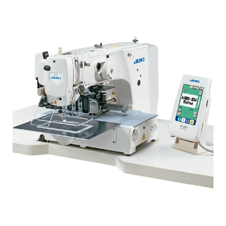
JUKI MEB-3200C User manual

MEB-3200C
INSTRUCTION MANUAL

CONTENTS
1. SPECIFICATIONS....................................................................................... 1
2. NAME OF EACH COMPONENT ................................................................ 2
(1) Names of the sewing machine main unit............................................................... 2
3. INSTALLATION........................................................................................... 3
(1) Installing the air hose .............................................................................................. 3
(2) Raising and returning the sewing machine........................................................... 3
(3) Installing the thread stand ...................................................................................... 5
(4) Installing the operation panel base........................................................................ 5
(5) Installing/removing the presser unit ...................................................................... 6
(6) Attaching the dust bag ............................................................................................ 7
(7) Installing the air gun................................................................................................ 7
4. PREPARATION BEFORE OPERATION..................................................... 8
(1) Lubricating the machine and how to lubricate...................................................... 8
(2) Attaching the needle.............................................................................................. 10
(3) Threading the machine head ................................................................................ 11
(4) How to set the cloth............................................................................................... 13
(5) USB connectors ..................................................................................................... 14
5. STRUCTURE OF THE OPERATION SWITCH......................................... 15
(1) Operation panel configuration.............................................................................. 15
(2) Temporary stop switch .......................................................................................... 17
(3) Hand switch............................................................................................................ 17
(4) Foot switch ............................................................................................................. 17
6. HOW TO USE THE OPERATION PANEL ................................................ 18
(1) Basic operation of the sewing machine............................................................... 18
(2) Creating a pattern .................................................................................................. 18
(3) Setting the thread tension..................................................................................... 19
(4) Temporarily stopping the sewing machine ......................................................... 20
(5) Performing re-sewing ............................................................................................ 21
(6) Performing threading............................................................................................. 21
(7) How to use the counter ......................................................................................... 22
(8) How to change the knife operation ...................................................................... 22
(9) Changing the operation mode .............................................................................. 23
(10) Setting the clock .................................................................................................. 23
7. SETTING PROCEDURE OF THE SEWING DATA................................... 25
(1) Setting the lockstitch buttonhole sewing data.................................................... 25
(2) Setting sewing data for the eyelet buttonhole .................................................... 26
(3) Setting sewing data for the radial stitch eyelet................................................... 26
(4) Setting sewing data for the straight bar shape................................................... 27
(5) Setting sewing data for the taper bar shape ....................................................... 27
i

(6) Setting sewing data for the round bar shape...................................................... 28
(7) Setting sewing data for the round bar 2 shape................................................... 28
(8) Sewing data list...................................................................................................... 29
8. ADJUSTMENT OF EACH PART .............................................................. 34
(1) Replacing the cloth cutting knife and the knife holder ...................................... 34
(2) Setting the knife pressure of the standard type.................................................. 35
(3) Setting the knife pressure for the multicutting type........................................... 36
(4) Worn-out of the knife holder face......................................................................... 37
(5) Setting the material thickness of the cloth cutting knife ................................... 37
(6) Adjusting the stitch bite width.............................................................................. 38
(7) Adjusting the presser ............................................................................................ 39
(8) Adjusting the presser opening amount ............................................................... 39
(9) Adjusting the feeding amount of the needle thread ........................................... 41
(10) Adjusting the thread take-up thread guide........................................................ 41
(11) Adjusting the remaining amount of the gimp (J and C types) ......................... 42
(12) Adjusting the gimp thread tension (J and C types) .......................................... 42
(13) Hand LED light ..................................................................................................... 43
9. HOW TO USE THE VARIOUS FUNCTIONS ............................................ 44
(1) Performing procedure of the cycle sewing ......................................................... 44
(2) Operating procedure of thread tension compensation of each section........... 45
(3) Operating procedure of shape compensation of each section ......................... 47
(4) Changing the setting position of cloth ................................................................ 48
(5) Changing over the mode of the start switch ....................................................... 48
(6) Changing of the presser movement..................................................................... 48
(7) Changing over the counter (DOWN counting) .................................................... 49
(8) Stop before cloth cut mode................................................................................... 50
(9) Communication function....................................................................................... 50
10. MAINTENANCE...................................................................................... 52
(1) Height of the needle bar ........................................................................................ 52
(2) Timing between the needle and the looper ......................................................... 52
(3) Clearance between the needle and the looper.................................................... 54
(4) Adjusting the needle guard................................................................................... 54
(5) Installation positions of the spreaders and the timing to open/ close the
spreaders .............................................................................................................. 55
(6) Position of the presser foot and the needle entry point..................................... 57
(7) Adjusting the knife dropping position ................................................................. 57
(8) Installing position of the needle thread trimming knife ..................................... 58
(9) Adjusting the looper thread trimming.................................................................. 60
(10) Cleaning................................................................................................................ 61
(11) Draining................................................................................................................. 61
(12) Replacing the electrical control box .................................................................. 61
(13) How to change over the power supply .............................................................. 62
ii
(14) Standard of replacing time of the gas spring.................................................... 63
(15) Replacing the gas spring .................................................................................... 63
(16) Disposing of batteries ......................................................................................... 68
11. EXCHANGING GAGUE PARTS AND OPTIONAL ................................. 69
(1) Changing the type of thread trimmer................................................................... 69
(2) Exchanging gauge parts ....................................................................................... 69
12. TROUBLES AND CORRECTIVE MEASURES IN SEWING.................. 75
13. MEMORY SWITCH ................................................................................. 78
(1) Operating procedure.............................................................................................. 78
(2) Memory switch list................................................................................................. 79
14. ERROR LIST........................................................................................... 87
15. STANDARD PATTERN LIST .................................................................. 92
16. OPTIONS ................................................................................................ 94
(1) Installing the center marking light........................................................................ 94
(2) Fine adjustment of the laser marking projector.................................................. 95
(3) Installing the side marking light ........................................................................... 98
(4) Sewing radial stitch eyelets ................................................................................ 108
iii

- 1 -
1. SPECIFICATIONS
Specifications S type, R type J type C type
Application Men’s and ladies’ wear Jeans, working wear Cotton pants, working wear
Sewing speed 400 to 2,200 sti/min (adjustable in 100 sti/min steps)
Thread trimming
type
Long thread trimming Short thread trimming
Stitch length
(Note 1)
10 to 38 mm (with thread
trimmer)
10 to 50 mm (In case loop-
er thread trimming device
is removed)
24 to 32 mm
* In case of taper bar, up
to 34 mm
16 to 24 mm
* In case of taper bar, up
to 26 mm
Stitch bite width
(Notes 2 and 3)
2.0 to 3.2 mm 2.6 to 4.0 mm 2.0 to 3.2 mm
Taper bar length 0 mm, 3 to 15 mm
Lift of presser foot 13 mm (Max. 16 mm)
Method of chang-
ing sewing shape
Program selection method
Buttonhole cutting
system
Cut-before knife, cut-after knife, without knife
Feed system Intermittent feed by stepping motor
Cloth cutting drive Vertical drive by stepping motor (Pressure can be adjusted.)
Needle (Note 2) DO×558
#90 to #110
DO×558
#90 to #110
DO×558
#110 to #120
Safety device Temporary stop switch and automatic stop function at the time of detection of trouble
Lubricating oil JUKI New Defrix Oil No. 2 (Oiling system)
Air pressure 0.49 Mpa
Air consumption 6R/ min (8-cycle/min)
Dimensions 1,060 mm (W) × 790 mm (L) × 1,230 mm (H) (Excluding thread stand)
Power consump-
tion
300 VA
Gross weight 179 kg
Noise
- Equivalent continuous emission sound pressure level (LpA) at the workstation :
A-weighted value of 81.0 dB; (Includes KpA = 2.5 dB); according to ISO 10821- C.6.3
-ISO 11204 GR2 at 2,200 sti/min.
- Sound power level (LWA) ;
A-weighted value of 88.0 dB; (Includes KWA = 2.5 dB); according to ISO 10821- C.6.3
-ISO 3744 GR2 at 2,200 sti/min.
Note 1.
For the short thread trimming type, stitch length can be changed by changing the optional presser
set.
S set : 16 to 24 mm, M set : 24 to 32 mm, L set : 32 to 40 mm
Note 2. Stitch bite width and needle size at the time of delivery are as follows.
S and R types J type C type
Stitch bite width 2.3 mm 3.6 mm 2.5 mm
Needle size #100 #110 #110
Note 3. By changing to the optional looper, left and spreader, left, the range of stitch bite width can be
changed to 2.0 to 3.2 ,/ 2.6 to 4.0.
Note 4. In case of the machine with the needle thread clamp unit or with the multicutting device,
refer to the respective Instruction Manuals together with this Instruction Manual.
When changing stitch bite width or needle size, check installing position and open/close timing
of needle, looper, and spreader, and clearance between needle and needle guard.

- 2 -
2. NAME OF EACH COMPONENT
(1) Names of the sewing machine main unit
❶
❷
❸
❹
❺
❻
❼
❽
❾
❶Temporary stop switch
❷Presser switch
❸Start switch
❹Operation panel
❺Control box
❻Power switch
❼Hand pulley
❽Machine head
❾Thread stand
Feed base
Cloth cutting dial
・Hand pulley ❼
The needle bar can be lifted or lowered by hand with the hand-
pulley.
・Cloth cutting dial
The cloth cutting knife can be lifted or lowered by hand with
the cloth cutting dial. (When the power is turned OFF.)
❼
Hand pulley ❼and cloth cutting knife rotate in accor-
dance with the rotation of the sewing machine and the
drive of the cloth cutting knife.
Be careful not to allow your hands or the like to touch to
them during operation of the sewing machine.

- 3 -
■Connecting the air hose
Connect the air hose to the regulator using
the hose band and the one-touch socket joint
supplied with the machine.
■Adjustment of air pressure
Open air cock ❶, pull up and turn air adjustment
knob ❷and adjust so that air pressure indicates
0.45 to 0.55 MPa. Then lower the knob and fix it.
* Close air cock ❶to expel air.
1) Remove the fixing screws, right and left for
transportation.
(8 mm wrench is supplied with the machine.)
Retain the screws since they are neces-
sary when moving the sewing machine.
Be sure to attach them when moving the
sewing machine.
(2) Raising and returning the sewing machine
3. INSTALLATION
Open
❶
❷
Fixing screw, left
(1) Installing the air hose
Close
Fixing screw,
right
DANGER :
1. Ifyoundthesewingmachineistooheavytolift,thegasspringmayhavemalfunctioned
due to outgassing.
Never lift the sewing machine in such a state since the machine can drop to pinch hands,
ngersandarmsresultinginseriousinjury.
* Be sure to fully understand "10.(14) Standard of replacing time of the gas spring" P.63 and
"10.(15) Replacing the gas spring" P.63 before putting the sewing machine into operation.
2. Inordertopreventpinchingofhands,ngersandarmsthatcanresultinaseriousinjury,be
sure to strictly observe the following when carrying out work.
2-1. Be sure to hold the rib on the bed periphery when holding the sewing machine.
2-2. Be sure to lock the hinge stopper to firmly secure the sewing machine in its raised
position.

- 4 -
3) When returning the sewing machine, support
periphery ribs ❶of the machine bed with your
left hand, hold grip ❹of the hinge stopper
section with your right hand, pull it to this side
(direction A) to release the lock and slowly
lower the sewing machine after confirming
that there is no tool such as screwdriver and
the like in the bottom cover.
❹
A4) Take your right hand off from the hinge stop-
per section, support periphery ribs ❶of ma-
chine bed with your both hands, and further
lower the sewing machine.
When returning
sewing machine
to its home
position
When raising
sewing machine
❺
❹
❸
❺
❹
❶
❷
❶
2) When raising the sewing machine, push feed base ❷away from you (in the direction of the arrow),
then hold periphery ribs ❶located on the front side of the sewing machine bed to slowly lift it.
At this time, do not hold feed base ❷and feed guide shaft fixing base ❸.
DANGER :
1. Do not hold any part other than periphery ribs ❶of machine head.
2. Conrmthathingestopper❹is locked with support shaft ❺.
CAUTION :
If you raise the sewing machine from its home position with the feed base remained near side,
thefeedbasecanmovetopinchhandsandngersleadingtoanunexpectedinjury.
DANGER :
1. Do not lower the sewing machine
while keeping pulling the hinge stop-
per in direction A, in order to prevent
pining of fingers, hands and arms
under the sewing machine leading to
a serious injury.
2. Do not hold feed base ❷and feed
guide shaft fixing base ❸.

- 5 -
(3) Installing the thread stand
(4) Installing the operation panel base
❶
❷
5) The sewing machine stops once more at the
final stage of lowering for the safety. Support
the periphery ribs of machine bed with your
left hand, hold the grip of hinge stopper sec-
tion with your right hand to release the lock
and slowly lower the sewing machine follow-
ing the description of step 3).
Fix operation panel base ❶at the dotting punch
section on the machine table with wood screw ❷.
Protection vinyl is coated on the surface
of the operation panel. Remove it.
1) Assemble thread stand unit ❶.
2) Insert it in the hole located in the rear of the
machine table, and tighten locknut ❷to fix
the thread stand.
When the ceiling wiring i s possible, pass
the power cord through the spool rest
rod.
DANGER :
Take care to prevent pinching of hands
and fingers between the sewing machine
and the bottom cover. In particular,
never lower the sewing machine holding
parts other than the bed rib with two or
more workers, since doing so can cause
pinching o f hands, fingers and arms
leading to a serious injury.
❶❶
❷

- 6 -
When installing the presser unit ❺,
insert correctly thread t rimming driving
arm roller ❼into the concave in looper
thread trimming cylinder click ❻. If the
roller is off, the looper thread trimming
unit interferes with the throat plate during
sewing. As a result, component breakage
will be caused.
❻
❶
❷
❸
❷
❸
❺
❹
❺
❶
❹
❻
❼
(5) Installing/removing the presser unit
❻
❶
❺
■How to remove
1) Turn clamp holding plate ❶to remove from
presser plate ❺.
2) Lifting presser plate ❺, remove it so as to
draw it.
When moving the feed base by hand, or
removing/at taching the presser unit ,
be careful so that the cloth cutting knife
does not come in contact with the holding
plates, orthe thread trimming unit does
not come in contact with the throat plate.
■How to install
1) Install the presser unit so that presser lever ❸
fits in the letter “U” of presser base ❷.
2) Adjust the hole of presser plate ❺to cloth
open pin ❹.
3) Turn clamp holding plate ❶to hold presser
plate ❺.
It is comparatively easy to install or
remove the presser unit by moving feed
base ❻to the cloth cutting position.
([ ] button is convenient. Refer to
"6.(6) Performing threading" P.21.)
When moving feed base ❻by hand, fol-
low the aforementioned caution.

- 7 -
(7) Installing the air gun
1) Insert spiral tube ❷of air gun ❶into the va-
cant side of double-ended joint ❸.
2) Attach hook ❹next to power switch ❺.
Then, hang air gun ❶on the hook as shown
in the left figure on the left.
(6) Attaching the dust bag
❶❸
❷
Attach dust bag ❶to clamp ❷located in the rear
face of the table and insert dust hose ❸into the
bag.
❸
❷
❷
❶❶
❹
❺

- 8 -
4. PREPARATION BEFORE OPERATION
❶
❷
1) Raise the machine head.
2) Lubricate bed oil tank ❷up to the MAX. line.
3) Return the machine head to its home position.
(1) Lubricating the machine and how to lubricate
■Lubricating the arm oil tank
* Use JUKI New Defrix Oil No. 2.
Lubricate arm tank ❶to such an extent of
approximately 80 %.
■Lubricating the bed oil tank
WARNUNG :
Turn OFF the power before starting the work so as to prevent accidents caused by abrupt start
of the sewing machine.
DANGER :
Be sure carry out the work while observing the following in order to protect against pinching of
hands, fingers and arms between the sewing machine and the bottom cover, which can result
in serious injury, when you raise the sewing machine from its home position.
• Be sure to lock the hinge stopper to firmly secure the sewing machine in its raised position.
* Read and check how to rise/return the sewing machine described on "3.(2) Raising and
returning the sewing machine" P.3 to P. 5.

- 9 -
❶
❷
❺
❹❸
❺
Front
Rear
❻
■Lubricating the looper and spreader components
1) Remove the presser plates, left
and right, and raise the machine
head.
2) Apply two to three drops of oil to
looper link ❶, spreader link ❷,
spreader, right ❸, spreader, left
❹and spreader actuating cam ❺.
1. Be sure to lubricate the
components once a day.
If the frequency of lubri-
cation is small, especially,
worn out of ❸, ❹and ❺is
caused and stitch skipping
or needle breakage will
occur.
2. Apply oil to the oil wicks
and the felts ( looper cam
oiling felt ❻or the like)
in the machine bed at the
time of delivery or after an
extended period of disuse.
DANGER :
Be sure carry out the work while observing the following in order to protect against pinching of
hands, fingers and arms between the sewing machine and the bottom cover, which can result
in serious injury, when you raise the sewing machine from its home position.
• Be sure to lock the hinge stopper to firmly secure the sewing machine in its raised position.
* Read and check how to rise/return the sewing machine described on "3.(2) Raising and
returning the sewing machine" P.3 to P. 5.

- 10 -
The correct direction of the needle is that needle
thread guide ❶faces the opposite side of groove
❷of the needle.
1. Use the most suitable size of needle
in accordance with the kind and thick-
ness of thread and kind of material to
be used.
2. When changing the size of needle, be
sure to adjust the clearance between
the needle and the looper. (Refer to "10.
(3) Clearance between the needle and
the looper" P.54.)
■Lubricating the needle bar and cam components
❺
❻
❺
❺
❺
❺
❺
❺
❶
❷
❸
❹
❶
Put needle as
far as it goes.
❶
❷
(2) Attaching the needle
Lubricate the components at the time of delivery or after an extended period of disuse.
1) Loosen setscrews ❶and remove face plate
❷.
2) Apply one to two drops of oil to needle bar
bushing ❸and needle bar ❹.
3) Apply oil to the felts and the oil wicks in the
face plate section of the sewing machine.
Remove the cover with care since the air
tube is connected with the cord.
5) Apply oil to the felts and the oil wicks in the
sewing machine arm.
6) After lubrication, install face plate ❷and up-
per face cover ❻.
Be careful not to allow the cords to be
caught in the machine.
4) Loosen setscrew ❺and remove the upper
face cover ❻.
WARNUNG :
Turn OFF the power before starting the work so as to prevent accidents caused by abrupt start
of the sewing machine.
Standard With thread
tension disk (OP)

- 11 -
(3) Threading the machine head
Ⓐ
Ⓑ
Ⓒ
Ⓑ
Ⓐ
Standard Optional
Threading the lower thread (looper thread)
Threading the upper thread (needle thread)
WARNUNG :
Turn OFF the power before starting the work so as to prevent accidents caused by abrupt start
of the sewing machine.
DANGER :
1. If you find the sewing machine is too heavy to lift, the gas spring may have malfunctioned
due to out gassing.
Never lift the sewing machine in such a state since the machine can drop to pinch hands,
fingers and arms resulting in serious injury.
* Be sure to fully understand "10.(14) Standard of replacing time of the gas spring" P.63 and
"10.(15) Replacing the gas spring" P.63 before putting the sewing machine into operation.
2. Inordertopreventpinchingofhands,ngersandarmsthatcanresultinaseriousinjury,
be sure to strictly observe the following when carrying out work.
2-1. Be sure to hold the rib on the bed periphery when holding the sewing machine.
2-2. Be sure to lock the hinge stopper to firmly secure the sewing machine in its raised
position.

- 12 -
1. Whenpassingthelooperthread,turnthelooperbracketby180˚andpassit.
2. Pass the looper thread and gimp through the needle hole in the throat plate and pull them
out from hole ❶. Then clamp them at ❷of the presser plate and perform a few stitch sew-
ing to remove the looper thread and gimp (2 pcs.). When the sewing is completed, the looper
thread is retained with the looper thread clamp and gimp with the gimp clamp. If thread waste
is clamped, remove it since clamping becomes incomplete and stitch skipping at the sewing
start will be caused. [ Refer to "10.(9) Adjusting the looper thread trimming" P.60.]
❶
❷
Insert thread in
the groove.

- 13 -
1) Enter the sewing material until it comes in contact with cloth patches ❶, right and left.
2) Loosen setscrews ❷, right and left and adjust the sewing position by moving the cloth patches to
and fro.
(4) How to set the cloth
In case of thin thread, insert
gimp in the gimp presser plate.
*
❶
❶
❶
❷
❷
❷
Pass gimp through the
groove on the thread tension
disk shaft.
S and R
types
J,C type
Threading the machine with gimp
*S type : 13.5 to 30 mm
*J, C types : 10.0 to 26 mm

- 14 -
(5) USB connectors
1) Open cover ❶to find USB connectors ❷and
❸.
Connector ❷
This USB connector is used for communi-
cation. It can be used to write/import pattern
information, etc. to/from the USB thumb drive.
Connector ❸
This USB connector is exclusively used for
power supply.
It is able to take the 5 V/1 A power supply.
❶
❷
❸

- 15 -
5. STRUCTURE OF THE OPERATION SWITCH
❶ ❷ ❸
❹
❺
❼
❻
❾
❶
[List of display items]
No. Display Description
❶
Single pattern Pattern No.
(Normal
display)
(Inverted
display)
Cycle pattern
(Normal
display)
(Inverted
display)
❷
Knife operation (No display when
the knife does not operate)
(Cut-before
knife)
(Cut-after
knife)
No. Display Description
❸Sewing speed
❹Needle thread tension
❺Looper thread tension
❻Knife No.
❼Number of stitches
❽Pattern No. of the current step
Current step
Total number of steps
Current time
❽
(1) Operation panel configuration

- 16 -
[List of pattern shapes]
[List of buttons]
No. Display Description
❾
Lockstitch buttonhole without
bartack
(With knife) (Without knife)
Lockstitch buttonhole with taper
bar
(With knife) (Without knife)
Lockstitch buttonhole with
straight bar
(With knife) (Without knife)
Lockstitch buttonhole with round
bar
(With knife) (Without knife)
Lockstitch buttonhole with round
bar 2
(With knife) (Without knife)
Radial stitch eyelet
(With knife) (Without knife)
No. Display Description
▲▼button
Changes the pattern number
or the data number
+ - button
Changes data
EDIT button Edits data or selects the menu
ENTER button Saves the changed data
WITH/WITHOUT
CLOTH OPEN-
ING OPERATION
changeover button
Changes over between with/
without of the cloth opening
operation.
Refer to "6.(5) Performing
re-sewing" P.21 for details.
CLOTH OPENING
OPERATION TIM-
ING changeover
button
Changes over the timing of the
cloth opening operation
COUNTER button Displays the counter
AUTO MODE
changeover button
Changes over the mode to the
automatic mode
No. Display Description
❾
Eyelet buttonhole without bartack
(With knife) (Without knife)
Eyelet buttonhole with taper bar
(With knife) (Without knife)
Eyelet buttonhole with straight
bar
(With knife) (Without knife)
Eyelet buttonhole with round bar
(With knife) (Without knife)
Eyelet buttonhole with round bar
2
(With knife) (Without knife)
Sewing length (Knife size for
radial stitch eyelet in the case of
a radial stitch eyelet)
No.
S001 Sewing speed
S002 Sewing length
S003 Cloth cutting interval
No. Display Description
TEST MODE
changeover button
Changes over the mode to the
test mode
MANUAL MODE
changeover button
Changes over the mode to the
manual mode
SEWING MODE
changeover button
Changes over the mode to the
sewing mode
KNIFE PRESSURE
button
Sets the knife pressure
RESET button Resets the error
THREADING but-
ton
Performs threading of the
machine head. Refer to "6.(6)
Performing threading" P.21
for details.
SET POSITION
changeover button
Changes over the cloth
setting position. Refer to
"6.(4) Changing the setting
position of cloth" P.48 for
details.
WITH/WITHOUT
KNIFE OPERA-
TION changeover
button
Changes over between with/
without of the knife opera-
tion. Refer to "6.(8) How to
change the knife operation"
P. 22 for details.
Mbutton Displays the menu
[Shortcut buttons for changing patterns]
Press the button to display the corresponding data to allow you to change the set value.
* Depending on the pattern shape, the buttons that are set to "disuse" will be disabled.
No.
S060 Needle thread tension /
S075 Looper thread tension
No.
S004 Stitch pitch
S005 Number of stitches of eyelet
Other manuals for MEB-3200C
1
Table of contents
Other JUKI Sewing Machine manuals

JUKI
JUKI DLD-5430N User manual

JUKI
JUKI SC-910N User manual

JUKI
JUKI PLC-2760NVM User manual

JUKI
JUKI MO-6800S/DD20 Series User manual

JUKI
JUKI IP-100 User manual

JUKI
JUKI MO-613V User manual

JUKI
JUKI IT-100D User manual

JUKI
JUKI MB-373N/BR10 User manual

JUKI
JUKI TL-15 User manual

JUKI
JUKI DDL-8700-7 Quick start guide

JUKI
JUKI PS-800-12080 User manual

JUKI
JUKI DLN-6390 User manual

JUKI
JUKI APW-896N/IP-420 User manual

JUKI
JUKI AMB-289/IP-420 User manual

JUKI
JUKI PLK-G4030R User manual

JUKI
JUKI MO-804 User manual

JUKI
JUKI MO-6704DA User manual

JUKI
JUKI AK118 User manual

JUKI
JUKI CP-170 User manual

JUKI
JUKI MP-G10-NC User manual