JUKI DLM-5400NDD-7 User manual

DLM-5400NDD-7
INSTRUCTION MANUAL

i
CONTENTS
I. SPECIFICATIONS........................................................................................ 1
II. SET-UP........................................................................................................ 3
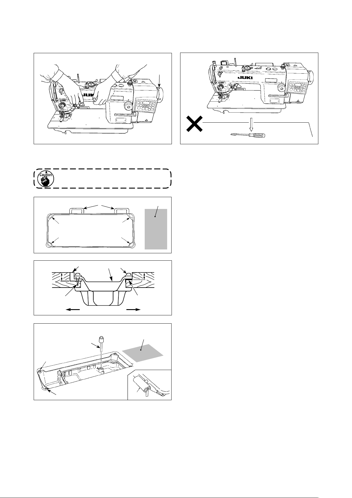
1. Installation .......................................................................................................................... 3
2. Installing the pedal sensor................................................................................................ 4
3. Installing the power switch (for CE)................................................................................. 5
4. Connecting the connector ................................................................................................ 6
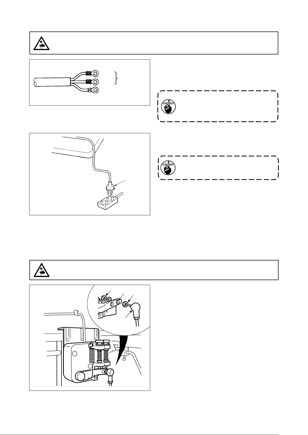
5. How to install the power plug ........................................................................................... 7
6. Attaching the connecting rod ........................................................................................... 7
7. Winding the bobbin thread ............................................................................................... 8
8. Installing the cloth chip guide .......................................................................................... 9
9. Adjusting the height of the knee lifter.............................................................................. 9
10. Installing the thread stand.............................................................................................. 10
11. Lubrication ....................................................................................................................... 10
12. Adjusting the amount of oil (oil splashes) .................................................................... 11
13. Attaching the needle ....................................................................................................... 13
14. Setting the bobbin into the bobbin case ....................................................................... 14
15. Adjusting the stitch length ............................................................................................. 14
16. Presser foot pressure...................................................................................................... 14
17. Hand lifter......................................................................................................................... 14
18. Adjusting the height of the presser bar......................................................................... 15
19. Threading the machine head.......................................................................................... 15
20. Thread tension................................................................................................................. 16
21. Thread take-up spring..................................................................................................... 16
22. Adjusting the thread take-up stroke .............................................................................. 16
23. Needle-to-hook relationship ........................................................................................... 17
24. Height of the feed dog..................................................................................................... 17
25. Tilt of the feed dog........................................................................................................... 18
26. Adjusting the feed timing................................................................................................ 18
27. Trimmer............................................................................................................................. 19
28. Adjusting the initial position of the moving knife ........................................................ 21
29.
Replacing the counter knife .............................................................................................21
30. Adjusting the counter knife pressure ............................................................................ 22
31. Changing the moving knife............................................................................................. 22
32. One-touch type manual reverse feed stitching ............................................................ 23
33. Wiper................................................................................................................................. 23
34. Other replaceable parts................................................................................................... 24
35. Installing the gauge......................................................................................................... 25
36. Pedal pressure and pedal stroke ................................................................................... 25
37. Adjustment of the pedal.................................................................................................. 26
38. Marker dots on the handwheel....................................................................................... 26

ii
III. FOR THE OPERATOR............................................................................. 27
1. Operating procedure of the sewing machine................................................................ 27
2. Setting procedure of the machine head ........................................................................ 28
3. Operation panel built in the machine head ................................................................... 29
4. Operating procedure of the sewing pattern .................................................................. 30
5. One-touch setting ............................................................................................................ 32
6. Setting of functions ......................................................................................................... 33
7. Production support function .......................................................................................... 34
8. Function setting list......................................................................................................... 36
9. Detailed explanation of selection of functions ............................................................. 40
10. Automatic compensation of neutral point of the pedal sensor................................... 50
11. Selection of the pedal specications............................................................................. 51
12. Setting of the auto lifter function ................................................................................... 51
13. Selecting procedure of the key-lock function............................................................... 52
14. Initialization of the setting data...................................................................................... 52
IV. MAINTENANCE....................................................................................... 53
1. Adjusting the machine head ........................................................................................... 53
2. Error codes....................................................................................................................... 54

– 1 –
I. SPECIFICATIONS
Application General fabric, medium-weight materials
Max. sewing speed 4,500 sti/min
Thread trimming speed 200 sti/min
Stitch length 4 mm
Presser foot lift (by knee lifter) 13 mm
Needle *1 DB × 1 (#14) #9 to 18, 134 (Nm 90) Nm 65 to 110 (for CE)
Lubricating oil JUKI CORPORATION GENUINE OIL 7
Noise
- Equivalent continuous emission sound pressure level (LpA) at the workstation :
A-weighted value of 81.0 dB; (Includes KpA = 2.5 dB); according to ISO 10821- C.6.2
-ISO 11204 GR2 at 4,000 sti/min.
A-weighted value of 80.0 dB; (Includes KpA = 2.5 dB); according to ISO 10821- C.6.2
-ISO 11204 GR2 at 3,500 sti/min.
*1: Needle used depends on the destination.
• The sewing speed preset at the time of shipping : 4,000 sti/min
Supply voltage Single phase 220V/230V/240V
Frequency 50Hz/60Hz
Operating environment Temperature : 5 to 35˚C
Humidity 35 - 85 %
Input 320VA

– 2 –
A
B
C
D
E
F
H
G
I
DRAWING OF TABLE
A4xø3.4 on the bottom surface, depth 20 (Drill a hole at the time of set-up.)
BInstalling position of drawer stopper (on the reverse side)
Cø18 drilled hole
D3xø13 drilled hole
E2xø3.5, depth 10
F2xø3.5, depth 10
Gø40±0.5 drilled hole
Hø16 depth 30
IC1.5 to C2.5 (hinge side only)

– 3 –
II. SET-UP
1. Installation
1) Carry the sewing machine with two persons as
shown in the gure above.
2) Do not put protruding articles such as the screw-
driver and the like at the location where the
sewing machine is placed.
Do not hold the handwheel ❶.
❶
3) Install the oil pan in such a way that it is support-
ed at the four corners of the grooves in the table.
Attach rubber hinge seats ❷to the table with
adhesive tape and nail them on the table.
4) For two rubber hinge seats located this side A,
secure machine head support rubber seats ❸to
the projecting portion of the table with nails ❹.
For two rubber hinge seats on the hinge side B,
secure machine head cushion seats ❺with nails.
Then, put oil pan ❻on the correct position.
5) Fit knee lifter pressing rod ❼. Fit hinge ❽into
the opening in the machine bed, and t the
machine head to table rubber hinge ❷before
placing the machine head on cushions ❾on the
four corners.
6) Securely attach head support rod to the table
until it goes no further.
❸❸
❺
❺
19.5mm23.5mm ❸
❹
❻
❺
A B
❾
❽
❼
❾
C
❷
C
❸

– 4 –
1. Be sure to install the machine head
support rod supplied with the unit.
2. If a pair of scissors or the like is
caught between the control box and
the table, the control box cover can
break. To prevent such an accident, do
not place anything on C section.
3. Be aware that the control box break-
age and/or oil leakage can occur if
operating the sewing machine with the
machine head support rod removed.
2. Installing the pedal sensor
1) Install the pedal sensor to the table with mounting
screws ❶supplied with the unit.
It is necessary to install the pedal sensor at such
a position that the connecting rod is perpendicu-
lar to the table.
2) After the completion of installation of the pedal
sensor on the table, place the sewing machine
head on the table.
❶
❽
❷

– 5 –
❶
1ø 220V-240V
❷
❸
3. Installing the power switch (for CE)
Do not insert the power plug into the plug
receptacle.
1) Remove screw ❶on the side face of the power
switch cover to open the power switch cover.
Blue Blue
Brown Brown
Green/
Yellow
Green/
Yellow
2) Pass AC input cord ❷(40145128),
❸(M6102461DAA) through the rear face of the
power switch. Bundle the cord with cable clip
band ❹to secure it.
3) Securely x the terminals of the AC input cord
❷(40145128), ❸(M6102461DAA)
by tightening
the screws at the specied locations.
4) Close the power switch cover. Tighten screw
❶
on the side face of the power switch cover.
❷
❹
WARNING :
1. Be sure to attach the ground wire (green/yellow) to the specied location (on the ground side).
2. Take care not to allow terminals to come in contact with each other.
3. When closing the power switch cover, take care not to allow the cord to be caught under it.

– 6 –
4. Connecting the connector
WARNING :
• To protect against personal injury resulting from abrupt start of the sewing machine, be sure to
turn the power OFF, unplug the machine and wait for ve minutes or more before installing the
pedal sensor.
• To prevent damage of device caused by maloperation and wrong specications, be sure to connect
all the corresponding connectors to the specied places. (If any of the connectors is inserted into
a wrong connector, not only the device corresponding to the connector can break but also it can
start abruptly, inviting the risk of personal injury.)
• To prevent personal injury caused by maloperation, be sure to lock the connector with lock.
• Do not connect the power plug until the connection of cords is completed.
• Fix the cords while taking care not to forcibly bend them or excessively clamp them with staples.
• As for the details of handling respective devices, read carefully the Instruction Manuals supplied
with the devices before handling the devices.
Do not insert the power plug into the wall
outlet.
Check to be sure that the power switch is
turned OFF.
1) Connect the connectors listed below to the con-
trol box in the order of ❶to ❸.
❶Pedal sensor cable
❷AC input cable
❸Machine head connector
For the connection ports of the cables, refer to
the connector layout drawing.
Be sure to fully insert the connectors into
the corresponding ports until they are
locked.
2) Draw out cable of the control box through cable
draw-out hole ❹to route it to the underside of
the sewing machine table.
3) Fix pedal sensor cable ❶and AC input cable ❷with a staple ❺.
Pedal sensor
❶
Slack
Underside of the table
❺
❺
❺
❹
❷
Pedal sensor
❶
Slack
Underside of the table
❺
❺
❹
❷
(For CE)
Connector connection diagram
Pedal
AC power supply
Machine head connector
❶
❹
❷
❸

– 7 –
2) Check that the power switch is in the OFF state.
Then, insert the power plug ❶coming from the
power switch into the plug receptacle.
In prior to the connection of the power
plug ❶, re-check the supply voltage spec-
ication indicated on the control box.
* The power plug ❶ is dierent in shape ac-
cording to the destination of the sewing
machine.
6. Attaching the connecting rod
Fix connecting rod ❶to installing hole of pedal lever
❷with nut ❸.
5. How to install the power plug
WARNING :
1. Be sure to attach the ground wire (green/yellow) to the specied location (on the ground side).
2. Take care not to allow terminals to come in contact with each other.
WARNING :
To protect against possible personal injury due to abrupt start of the machine, be sure to start the
following work after turning the power o and a lapse of 5 minutes or more.
1) Connect the power cord to power plug ❶. Con-
nect the blue and brown wires (1ø) to the power
supply side and the green/yellow wire to the earth
side as illustrated in the gure.
1. Be sure to prepare the power plug ❶
which conforms to the safety standard.
2. Be sure to connect the ground lead
(green/yellow) to the grounding side.
Blue
Brown
Green / Yellow
(ground wire)
AC 220-240V
1ø 220-240V
❶
❶
❷❸
❸

– 8 –
1) Insert the bobbin deep into the bobbin winder
spindle ❶until it will go no further.
2) Pass the bobbin thread pulled out from the
spool rested on the right side of the thread stand
following the order as shown in the gure on the
left. Then, wind clockwise the end of the bobbin
thread on the bobbin several times.
(In case of the aluminum bobbin, after winding
clockwise the end of the bobbin thread, wind
counterclockwise the thread coming from the
bobbin thread tension several times to wind the
bobbin thread with ease.)
3) Press the bobbin winder trip latch ❷in the direc-
tion of Aand start the sewing machine. The bob-
bin rotates in the direction of Cand the bobbin
thread is wound up. The bobbin winder spindle ❶
automatically as soon as the winding is nished.
4) Remove the bobbin and cut the bobbin thread
with the thread cut retainer ❸.
5) When adjusting the winding amount of the bobbin
thread, loosen setscrew ❹and move bobbin
winding lever ❷to the direction of Aor B. Then
tighten setscrew ❹.
To the direction of A: Decrease
To the direction of B: Increase
7. Winding the bobbin thread
6) In case that the bobbin thread is not wound evenly on the bobbin, loosen screw ❺and adjust the height
of bobbin thread tension ❽.
• It is the standard that the center of the bobbin is as high as the center of thread tension disk ❻.
• Adjust the position of thread tension disk ❻to the direction of Dwhen the winding amount of the bobbin
thread on the lower part of the bobbin is excessive and to the direction Ewhen the winding amount of
the bobbin thread on the upper part of the bobbin is excessive.
After the adjustment, tighten screw ❺.
7) To adjust the tension of the bobbin winder, turn the thread tension nut ❼.
1. When winding the bobbin thread, start the winding in the state that the thread between the
bobbin and thread tension disk ❻is tense.
2. When winding the bobbin thread in the state that sewing is not performed, remove the needle
thread from the thread path of thread take-up and remove the bobbin from the hook.
3. There is the possibility that the thread pulled out from the thread stand is loosened due to
theinuence(direction)ofthewindandmaybeentangledinthehandwheel.Becarefulofthe
direction of the wind.
D
E
B❸
❶
❻
❼
❻
❺
❻
A
C
❽
❹
❷

– 9 –
❶
❷
❸
❹
B
❸
A
8. Installing the cloth chip guide
Install cloth chip guide ❶on throat plate ❷to allow
all cloth chip to drop into the cloth chip guide.
Then, install drain oil guide ❸to the oil pan while
taking care of the following precautions.
1. Take care not to allow the tip of drain oil guide to
protrude left side of the extended line of surface
Aof throat plate cloth chip cover ❹.
2. Take care not to allow portion Bof the throat
plate cloth chip cover to come in contact with
drain oil guide when you raise or tilt the sewing
machine.
1) The standard height of the presser foot lifted
using the knee lifter is 10 mm.
2) You can adjust the presser foot lift up to 13 mm
using knee lifter adjust screw ❶.
3) When you have adjusted the presser foot lift
to over 10 mm, be sure that the bottom end of
needle bar ❷in its lowest position does not hit
presser foot ❸.
WARNING :
Be sure to turn the power OFF before the following work in order to prevent personal injury due to
unintentional starting of the sewing machine.
9. Adjusting the height of the knee lifter
❶
❷
❸

– 10 –
10. Installing the thread stand
1) Assemble the thread stand unit, and
insert it in the hole in the machine table.
2) Tighten nut ❶.
11. Lubrication
WARNING :
1. Do not connect the power plug until the lubrication has been completed so as to prevent acci-
dents due to abrupt start of the sewing machine,
2. To prevent the occurrence of an inammation or rash, immediately wash the related portions if oil
adheres to your eyes or other parts of your body.
3. If oil is mistakenly swallowed, diarrhea or vomitting may occur. Put oil in a place where children
cannot reach.
1. When you use a new sewing machine or a sewing machine after an extended period of dis-
use, use the sewing machine after performing break-in at 2,000 sti/min or less.
2. For the oil lubrication, purchase JUKI CORPORATION GENUINE OIL 7 (Part No. :
MML007600CA).
3. Be sure to lubricate clean oil.
4. Be aware that, if the oil is poured in the oil pan exceeding the marker "HIGH" A, oil leakage
can be caused.
5. Transporting the sewing machine with the sewing machine lled with oil can give rise to the
risk of oil leakage. Be sure to discharge oil from the sewing machine through drain cock.
A
B
❶❷
1) Before starting the sewing machine, ll oil pan ❶
with NEW DEFRIX OIL No.1 or JUKI CORPORA-
TION GENUINE OIL7 up to “HIGH” mark A.
2) Add oil before the oil surface comes down to
reach the “LOW” mark B.
3) When you operate the machine after lubrication,
you will see splashing oil through oil sight window
❷if the lubrication is adequate.
4) Note that the amount of the splashing oil is unre-
lated to the amount of the lubricating oil.
❶

– 11 –
①Amountofoil(oilsplashes)conrmationpaper ②Positiontoconrmtheamountofoil(oilsplashes)
Closelytthepaperagainstthewall
surface of the bed.
Oilsplashesconrmationpaper
3 - 10 mm
25 mm
* When carrying out the procedure described below in 2), remove the slide plate and take extreme caution
not to allow your ngers to come in contact with the hook.
1) If the machine has not been suciently warmed up for operation, make the machine run idle for approxi-
mately three minutes. (Moderate intermittent operation)
2) Place the amount of oil (oil spots) conrmation paper under the hook immediately after the machine stops
running.
3) Check to make sure that the oil surface in the oil pan remains in the range from "HIGH" to "LOW".
4) Conrmation of the amount of oil should be completed in ve seconds. (Check the period of time with a
watch.)
WARNING :
Be extremely careful about the operation of the machine since the amount of oil has to be checked
by turning the hook at a high speed.
12. Adjusting the amount of oil (oil splashes)
(1)Conrmationoftheamountofoilinthehook
1) Tilt the sewing machine. Turn oil amount adjust-
ment screw ❶, which is mounted on the front
bushing of lower shaft, in the "+" direction (direc-
tion A) to increase the oil amount (oil spots), or
in the "-" direction (direction B) to decrease it.
* The oil-amount +/- indication mark is shown on
the underside cover.
2) After the amount of oil in the hook has been
properly adjusted with the oil amount adjustment
screw ❶, make the sewing machine run idle for
approximately 30 seconds to check the amount
of oil in the hook.
(2) Adjusting the amount of oil (oil spots) in the hook
70 mm
A
B
❶

– 12 –
1) The amount of oil shown in the samples on the
left should be nely adjusted in accordance with
sewing processes. Be careful not to excessively
increase/decrease the amount of oil in the hook.
(If the amount of oil is too small, the hook will be
seized (the hook will be hot). If the amount of oil
is too much, the sewing product may be stained
with oil.)
2) Check the oil amount (oil splashes) three times
(with three sheets of paper).
Splashes of oil from the hook
1 mm
Appropriate amount of oil (small)
(3) Sample showing the appropriate amount of oil in the hook
Appropriate amount of oil (large)
2 mm
Splashes of oil from the hook
①Amount of oil (oil splashes) conrmation paper
② Position to conrm the amount of oil
(oil splashes)
Oil splashes
conrmation paper
25 mm
70 mm
(4) Conrmation of the amount of oil supplied to the face plate parts
* When carrying out the work described below in
2), remove the face plate and take extreme cau-
tion not to allow your ngers to come in contact
with the thread take-up lever.
1) If the machine has not been suciently warmed
up for operation, make the machine run idle for
approximately three minutes. (Moderate intermit-
tent operation)
2) Place the amount of oil (oil spots) conrmation
paper under the hook immediately after the ma-
chine stops running.
3) Check to make sure that the oil surface in the oil
pan remains in the range from "HIGH" to "LOW".
4) The time required for the conrmation of the
amount of oil (oil splashes) should be completed
in ten seconds. (Measure the period of time with
a watch.)
1) Adjust the amount of oil supplied to the thread
take-up and needle bar crank ❷by turning adjust
pin ❶.
2) The minimum amount of oil is reached when
marker dot Ais brought close to needle bar
crank ❷by turning the adjust pin in direction B.
3) The maximum amount of oil is reached when
marker dot Ais brought to the position just
opposite from the needle bar crank by turning the
adjust pin in direction C.
Minimum
Maximum
❶
❷
A
B
C
❶
(5) Adjusting the amount of oil supplied to the face plate parts

– 13 –
(6) Sample showing the appropriate amount of oil supplied to the face plate parts
1) The state given in the gure shows the appropri-
ate amount of oil (oil splashes). It is necessary to
nely adjust the amount of oil in accordance with
the sewing processes. However, do not exces-
sively increase/decrease the amount of oil in the
hook. (If the amount of oil is too small, the face
plate parts will be hot or seize. If the amount of oil
is too much, the sewing product may be stained
with oil.)
2) Check the oil amount (oil splashes) three times
(with three sheets of paper).
Use the specied needle for the machine. Use the
proper needle in accordance with the thickness of
thread used and the kinds of the materials.
1) Turn the handwheel until the needle bar reaches
the highest point of its stroke.
2) Loosen screw ❷, and hold needle ❶with its
indented part Afacing exactly to the right in
direction B.
3) Insert the needle fully into the hole in the needle
bar in the direction of the arrow until the end of
hole is reached.
4) Securely tighten screw ❷.
5) Check that long groove Cof the needle is facing
exactly to the left in direction D.
When polyester lament thread is used,
if the indented part of the needle is tilted
toward operator's side, the loop of thread
becomes unstable. As a result, hangnail
of thread or thread breakage may occur.
For the thread that such phenomenon
is likely to occur, it is eective to attach
the needle with its indented part slightly
slanting on the rear side.
13. Attaching the needle
WARNING :
Be sure to turn the power OFF before the following work in order to prevent personal injury due to
unintentional starting of the sewing machine.
S
plashes of oil from the thread take-up lever
1 mm
Appropriate amount of oil (large)
Appropriate amount of oil (small)
2 mm
S
plashes of oil from the thread take-up lever
C
D B
A
❷
❶

– 14 –
1) Pass the thread through thread slit A, and pull
the thread in direction C. By so doing, the thread
will pass under the tension spring and come out
from notch B.
2) Check that the bobbin rotates in the direction of
the arrow when thread is pulled.
14. Setting the bobbin into the bobbin case
15. Adjusting the stitch length
16. Presser foot pressure
17. Hand lifter
* The dial calibration is in millimeters (reference
value).
1) Turn stitch length dial ❶in the direction of the
arrow, and align the desired number to marker
dot Aon the machine arm.
1) Loosen nut ❷. As you turn presser spring regula-
tor ❶clockwise (in direction A), the presser foot
pressure will be increased.
2) As you turn the presser spring regulator ❶count-
er-clockwise (in direction B), the pressure will be
decreased.
3) After adjustment, tighten nut ❷.
The standard value of the pressure regulating thumb
screw is 29 to 32 mm.
In the case you want to stop the sewing machine
with its presser foot lifted, turn presser foot lifting
lever ❶in direction A.
29 to 32 mm
B
C
A
❷
❶
A
B
❶
A
A
❶

– 15 –
1) Loosen setscrew ❶, and adjust the presser bar
height or the angle of the presser foot.
2) After adjustment, securely tighten the setscrew
❶.
18. Adjusting the height of the presser bar
19. Threading the machine head
WARNING :
Be sure to turn the power OFF before the following work in order to prevent personal injury due to
unintentional starting of the sewing machine.
WARNING :
Be sure to turn the power OFF before the following work in order to prevent personal injury due to
unintentional starting of the sewing machine.
❶
❶
❷
❹
❺
❽
❾
❻
❼
❸

– 16 –
(1) Changing the stroke of thread take-up
spring ❶
1) Loosen setscrew ❷.
2) As you turn tension post ❸clockwise (in direc-
tion A), the stroke of the thread take-up spring
will be increased.
3) As you turn tension post ❸counterclockwise (in
direction B), the stroke will be decreased.
(2) Changing the pressure of thread take-up
spring ❶
1) Loosen setscrew ❷, and remove thread tension
asm. ❺.
2) Loosen setscrew ❹.
3) As you turn tension post ❸clockwise (in direc-
tion A), the pressure will be increased.
4) As you turn the tension post ❸counterclockwise
(in direction B), the pressure will be decreased.
1) When sewing heavy-weight materials, move
thread guide ❶to the left (in direction A) to
increase the length of thread pulled out by the
thread take-up.
2) When sewing light-weight materials, move thread
guide ❶to the right (in direction B) to decrease
the length of thread pulled out by the thread take-
up.
3) Normally, thread guide ❶is positioned in a way
that marker line Cis aligned with the center of
the screw.
(1) Adjusting the needle thread tension
1) The length of thread remaining at the needle tip
after thread trimming is shortened by turning ten-
sion regulating nut No. 1 ❶clockwise in direction
A.
2) It is lengthened by turning the nut counterclock-
wise in direction B.
3) The needle thread tension is increased by turning
tension regulating nut No. 2 ❷clockwise in direc-
tion C.
4) It is decreased by turning the nut counterclock-
wise in direction D.
(2) Adjusting the bobbin thread tension
1) The bobbin thread tension is increased by turning
tension regulating screw ❸clockwise in direction
E.
2) It is decreased by turning the screw counterclock-
wise in direction F.
20. Thread tension
21. Thread take-up spring
22. Adjusting the thread take-up stroke
WARNING :
Be sure to turn the power OFF before the following work in order to prevent personal injury due to
unintentional starting of the sewing machine.
❶
❷
❸
❹
❺
❶
B
A
B
A
❶
❷
C
D
❸
EF
❶
B
C
A

– 17 –
If the clearance between the blade point
of hook and the needle is smaller than the
specied value, the blade point of hook
will be damaged. If the clearance is larger,
stitch skipping will result.
To adjust the height of the feed dog :
1) Loosen screw ❷of crank ❶.
2) Move the feed bar up or down to make adjust-
ment.
3) Securely tighten screw ❷.
If the clamping pressure is insucient,
the motion of the forked portion becomes
heavy.
Adjust the timing between the needle and
the hook as follows :
1) Turn the handwheel to bright the needle bar
down to the lowest point of its stroke, and loosen
setscrew ❶.
Adjusting the needle bar height.
2) Align marker line Aon the needle bar ❷with the
bottom end of the needle bar lower bushing ❸,
then tighten clamping screw ❶of the needle bar
connection.
Adjusting position of the hook ❺.
3) Loosen three setscrews of the hook, turn the
handwheel and align marker line Bon ascending
the needle bar ❷with bottom end of the needle
bar lower bushing ❸.
4) In this state, align hook blade point ❺with the
center of needle ❹, and adjust the clearance
provided between needle ❹and hook ato 0.04
to 0.1 mm (reference). Then, securely tighten the
hook setscrews (three pieces).
23. Needle-to-hook relationship
24. Height of the feed dog
WARNING :
Be sure to turn the power OFF before the following work in order to prevent personal injury due to
unintentional starting of the sewing machine.
WARNING :
Be sure to turn the power OFF before the following work in order to prevent personal injury due to
unintentional starting of the sewing machine.
❶
❷
0.8 to 0.9 mm
❶
A
B
❹
❺
a
B
❸
A
❷
Table of contents
Other JUKI Sewing Machine manuals

JUKI
JUKI HZL-25Z User manual

JUKI
JUKI HZL-30Z User manual

JUKI
JUKI SC-510 User manual

JUKI
JUKI LK-1900A-SS User manual

JUKI
JUKI MH-1410 User manual

JUKI
JUKI ACF-172-1790 Quick start guide

JUKI
JUKI HZL-T100 User manual

JUKI
JUKI MEB-3200 Series Quick start guide

JUKI
JUKI DDL-9000A Quick start guide

JUKI
JUKI DLN-9010A User manual