JUKI HZL-30Z User manual

SERVICE MANUAL
HZL-30Z
Portable Zigzag Sewing Machine

CONTENTS
[1] PRODUCT SPECIFICATIONS FOR HZL-30Z ································ 1
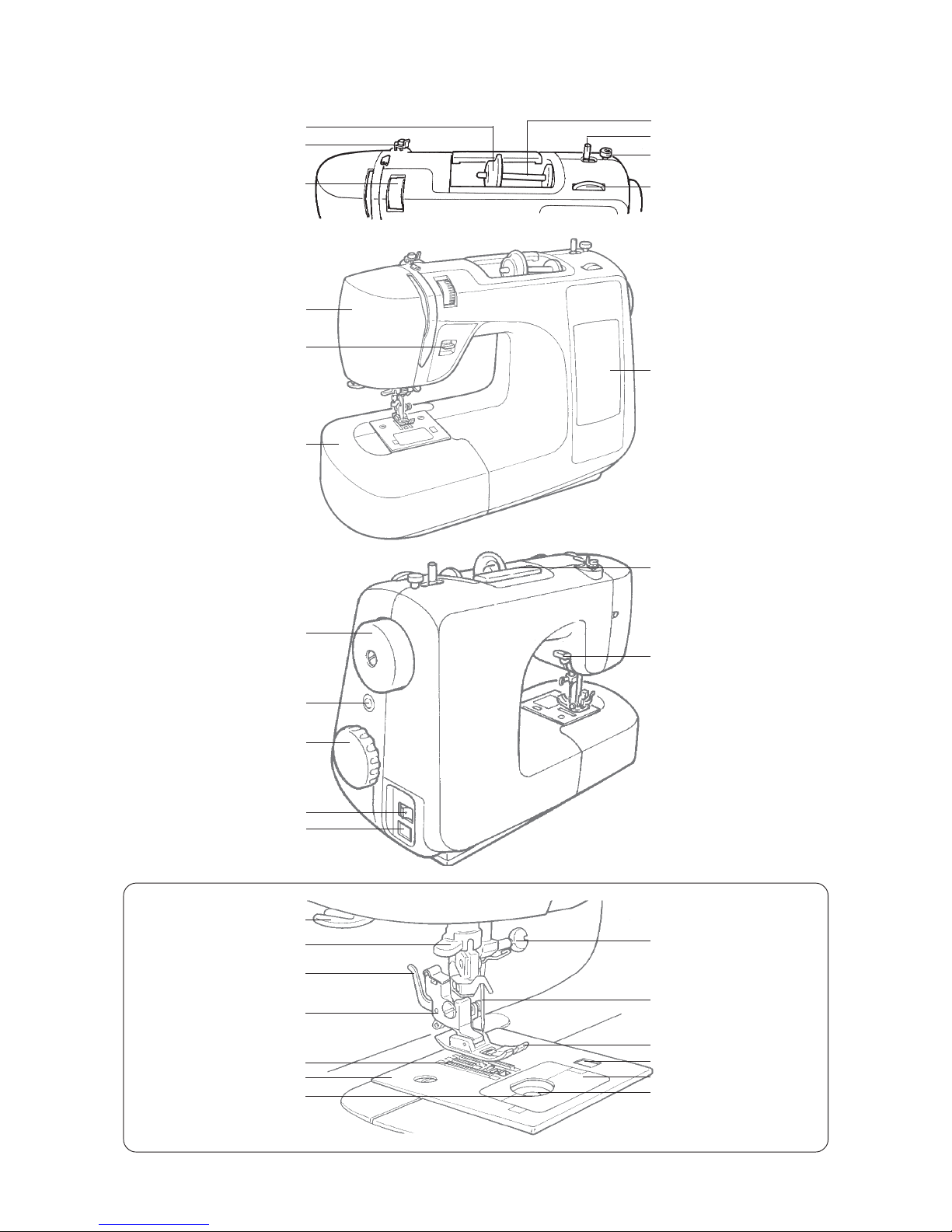
[2] NAMES OF THE RESPECTIVE COMPONENTS ·························· 2
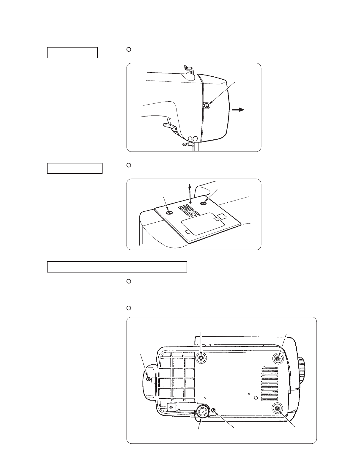
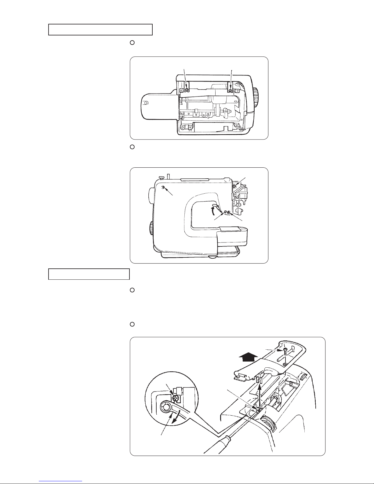
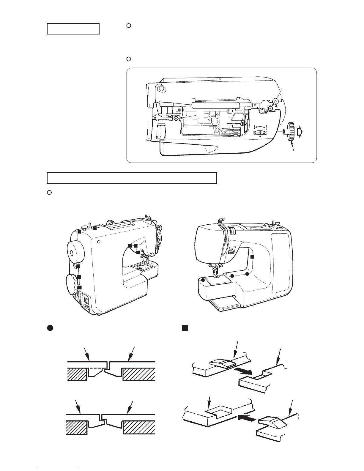
[3] HOW TO REMOVE THE OUTER COMPONENTS ······················· 3
[4] ADJUSTMENT OF THE RESPECTIVE COMPONENTS ·············· 7
WARNING :
• When disassembling, assembling or adjusting the sewing machine, remove the
power plug.
• When assembling, be careful about the electrical cord being caught with other
components, damage to the covered parts of the cord or miswiring.
• When replacing the part(s), use the genuine part(s).
To avoid the risk of fire, electric shock, injury to persons or damage to
components, especially keep the following:
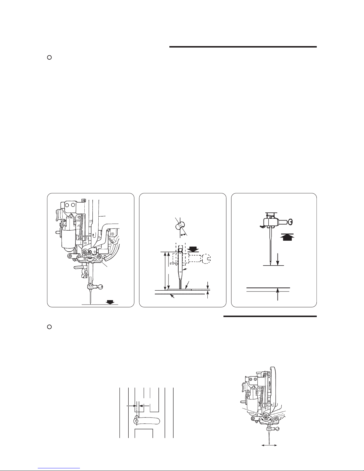
4-1 Adjusting the needle bar height ························································· 7
4-2 Adjusting the zigzag width needle entry position ···························· 7
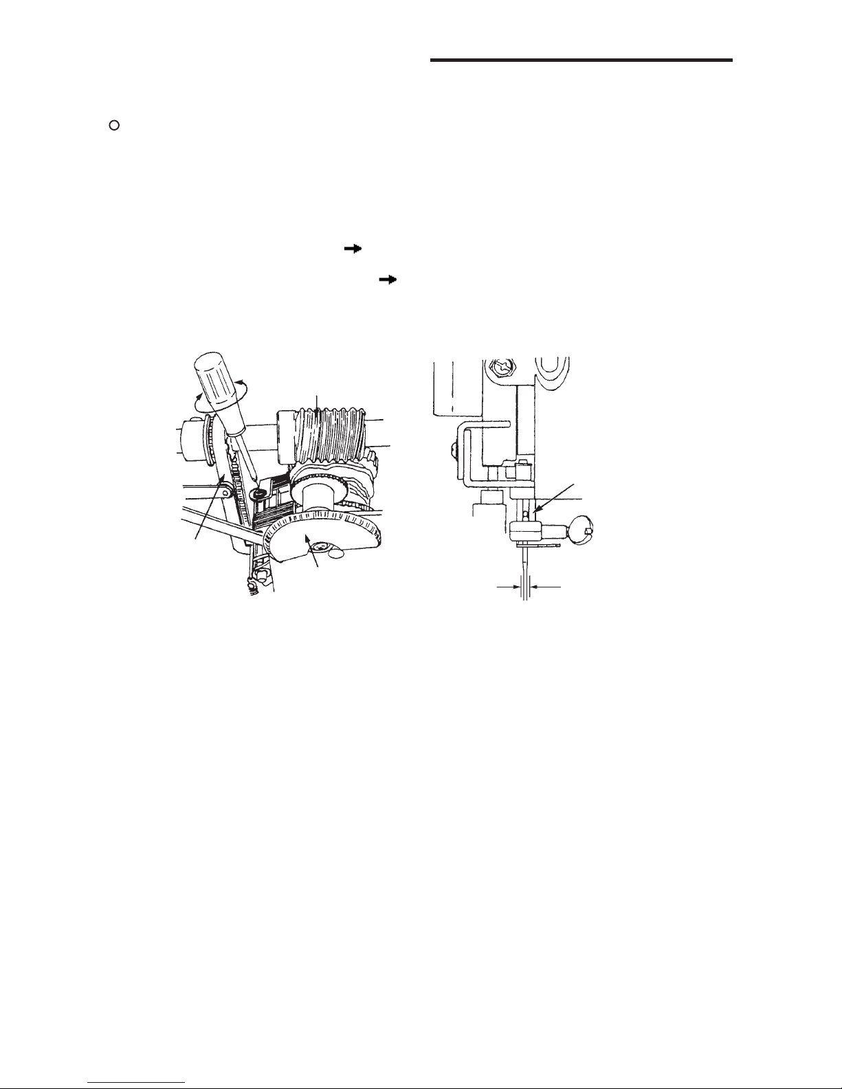
4-3 Adjustment of the straight stitch lock ··············································· 8
4-4 Needle throw ······················································································· 9
4-5 Feed dog height ················································································ 10
4-6 Timing belt ························································································· 10
4-7 Feed timing ························································································ 11
4-8 Needle-to-hook timing ······································································ 11
4-9 Clearance between the needle and the blade point of the hook ·· 12
4-10 Position of the bobbin case stopper plate ······································ 12
4-11 Adjusting the bobbin thread tension ··············································· 13
4-12 Opening amount of the tension disk ··············································· 13
4-13 Adjusting the needle thread tension ··············································· 14
4-14 Tension knob ····················································································· 14
4-15 Vertical position of the threader hook ············································ 15
4-16 Reverse stitch ··················································································· 15
4-17 Super stitch pattern ·········································································· 16
4-18 Height and position of the presser foot ·········································· 16
4-19 Button hole ························································································· 17
4-20 Motor belt tension ············································································· 17

[1] PRODUCT SPECIFICATIONS FOR HZL-30Z
-1--1-
-1--1-
-1-
• 220-230V AC common to 50/60 Hz
• Power switch : ON/OFF 2-step type
• 85W (Lamp : 240V/15W)
• Dimensions : 410 mm (W) X 180 mm (L) X 300 mm (H)
• Weight : 6.6 kg
• Computer-controlled controller type speed control
(No-heat type)
• AC230V 0.31A input 70W 169°C with temperature fuse
(built-in motor)
• Max. 5 mm
• Max. 4 mm
• Reverse stitch : Fixed feed pitch 2 mm ± 10%
• Built-in automatic threading devive
• Normal 6 mm Max. 9 mm
• Changeover of 17 steps by pattern dial
• Straight stitch (2 kinds of left stitch base line and center stitch
base line)
• Zigzag stitch (Fixed zigzag width type : 3 kinds of 1.67 mm,
3.33 mm and 5 mm)
• Straight stitch for elastic
• Blindstitch
• Blindstitch for elastic
• 3-step zigzag stitch
• Scallop stitch
• Buttonholing (2-step type)
• Overcasting
• Patchwork
• Stretch reinforcing stitch
• Pattern stitch (2 kinds)
• Arrow head
[Power source]
[Power consumption]
[Dimensions and weight]
[Speed control]
[Motor]
[Zigzag width]
[Feed amount]
[Threading]
[Lift of presser foot]
[Stitch selection]

[2] NAMES OF THE RESPECTIVE COMPONENTS
-2--2-
-2--2-
-2-
Handle
Thread Cutter
Needle threader
Presser foot release lever
Presser foot holder
Feed dog
Throat plate
Bobbin case
Needle clamp
Presser foot
Hook cover release button
Hook cover
Bobbin
Needle
Thread spool cap
Bobbin thread guide
Thread tension dial
Spool pin
Bobbin winder shaft
Bobbin winding regulator
Stitch length dial
Face cover
Auxiliary bed
Reverse stitch lever
Pattern display panel
Hand wheel
Stitch pattern dial
Light switch
Speed controller receptacle
Presser foot lever
Cover for buttonhole
adjusting

-3--3-
-3--3-
-3-
[3] HOW TO REMOVE THE OUTER COMPONENTS
1. Face cover
2. Throat plate
3. Base plate and free arm bottom cover
Remove setscrew (1) in the face cover and
remove the face cover.
Remove setscrews (2) and (3) in the throat plate and
remove the throat plate.
Remove setscrews (4), (5) and (6) in the rubber cushion of
the base plate, setscrew (7) of the base plate, and height
adjusting screw (8). (Base plate is removed.)
Remove setscrew (9) in the free arm bottom cover.
(1)
(2)
(3)
(6)
(5)
(4)
(7)
(8)
(9)

-4--4-
-4--4-
-4-
4. Front panel and rear panel
5. Thread spool cover
Remove setscrews (bottom) (10) and (11) in the
front panel (Mas. asm.).
Remove setscrews (12), (13) and (14) in the rear panel (asm.)
and setscrew (rear) (15) in the front panel (Mas. asm.).
(Lift the presser lifting lever when removing screw (15).)
Remove setscrew (upper) (16) in the thread spool cover and
setscrew (side) (17) in the thread spool cover. (Lower the thread
take-up support and insert a screwdriver from the face cover
side to remove setscrew (side) (17) in the thread spool cover.)
Open the rear panel in the rear and remove the thread spool
cover upward.
Thread take-up support
(10) (11)
(12)
(15)
(13)
(14)
(16)
(17)
(17)

-5--5-
-5--5-
-5-
6. Front panel
7. Remove front panel and rear panel from frame.
Loosen setscrew (front) (18) in the front panel (Mas. asm.),
setscrew (right) (19) in the front panel main unit and
setscrew (bobbin winder) (20) in the front panel main unit after
removing the thread spool cover.
Draw out pattern dial (21) knob.
There are hooking sections on the rear sides of both front and rear panel as illustrated in
the figures below. They are “engaging with the frame holes” and “engaging with the
respective covers”.
mark sectionmark section
(18)
(20)
(19)
Rear panel Front panel
Rear panel
Front panel
Rear panel Front panel
(21)

-6--6-
-6--6-
-6-
On condition that the presser lifting lever is lowered, open a little bit the joint section of
the front and rear covers as illustrated in the figure below.
(Rear panel)
• Remove the convex sections of the front panel and the rear panel from the frame so as to move the convex
sections up from the frame as illustrated in the figure below. Then open the respective panels.
• Open the right side (side of presser bar and face plate) of the rear panel and the joint section of the whole
panel is removed.
Note) Remove the rear panel so as to bring the rear panel near the hand wheel side at
the place of the power switch installing plate since there is a convex shape on
the rear panel.
(Front panel)
• Remove the convex sections of the front panel and the rear panel from the frame so as to move the convex
sections up from the frame in the same way as the rear panel above. Then open the panels.
[a] Draw the free arm section toward you. (Lower section of the front panel)
Then remove in the order below.
[b] Thread tension section
[c] Bobbin winder base section
Frame hole
Frame hole
[a]
[b]
[c]
[a]

[4] ADJUSTMENT OF THE RESPECTIVE COMPONENTS
4-1 Adjusting the needle bar height
Remove the face cover.
• Dimension from the bottom end of the needle bar pin to the top surface of the throat
plate : 19.7 mm
• The needle eyelet inclines to the right by 5° when a needle is attached.
1. Make a gauge needle which has cut a household needle, HA X 1 to dimension A
and attach it to the needle bar.
2. Prepare an appropriate piece of metal as thick as B. (A = 19.7 mm - B)
3. Bring the needle bar to the lowest point of its stroke and slightly loosen setscrew (1)
in the needle bar connection to the extent that the needle bar does not slip down.
4. Place the piece of metal on the throat plate, move the needle bar up or down by hand
so that the cut section of the gauge needle aligns with the top surface of the piece of
metal, and turn the needle bar by 5° as illustrated in the figure.
5. Temporarily tighten setscrew (1) and securely tighten it after re-confirming the
adjustment.
1. Attach a household needle, HA X 1 #14 to the needle bar and adjust the height of
the needle bar in the same way as the adjusting procedure above so that a distance
of 14.83 mm is provided between the top surface of the throat plate and the tip of the
needle when the needle bar is in the highest point of its stroke.
* Setscrew (1) can be loosened at the position where the needle bar is in the lowest
point of its stroke.
Adjustment
How to adjust 1
How to adjust 2
4-2 Adjusting the zigzag width needle entry position
Remove the face cover.
1. Select the zigzag pattern (zigzag width 5 mm) after turning the power switch ON.
2. Adjusting the needle entry position
Loosen the hexagonal eccentric screw and turn the hexagonal eccentric shaft to
adjust so that the tip of the needle is located in the position of 0.5 mm on the right
side from the center of the groove of left stitch base line of the throat plate when the
zigzag width is 5 mm as illustrated in the figure below.
3. After the adjustment, tighten the setscrew.
How to adjust
Lowest point
How to adjust 1 How to adjust 2
Hexagonal
eccentric shaft
Needle
(view from the upper part)
0 to 5°
Gauge needle
Lowest point
Piece of metal
Throat plate
Highest point
A19.7 mm
14.83 mm
HAx1 #14
Setscrew
0.5mm
(1)
-7--7-
-7--7-
-7-

4-3 Adjustment of the straight stitch lock
When selected the straight stitch (left-side needle line or central needle line), adjust the lateal play of the
needle bar.
1. Turn the stitch pattern dial and set to the straight stitch (left-side needle line).
2. Turn the hand wheel, and adjust so that the tip of the needle comes to the upper face
of the throat plate.
3. Turn the adjusting screw in the figure, and adjust so that the lateral play of the needle bar
becomes 0 to 1 mm (0.2 to 0.3 mm is recommended.).
No lateral play Change of the needle entry point, uneasy movement of the stitch
pattern dial, uneven rotation.
Excessive lateral play The movement of the needle bar is excessive when threading.
Adjustment
-8--8-
-8--8-
-8-
Worm gear
Timing belt
Feed knob
Needle bar
Lateral play: 0 to 1 mm
(0.2 to 0.3 mm is recommended)
Remove the front cover. (Including the front cover, throat plate, bottom cover and rear cover)

4-4 Needle throw
How to check the needle throw
1. Turn the stitch pattern dial, and select the zigzag width (maximum zigzag width).
2. Turn the hand wheel, and check the locus of the tip of the needle.
3. After the needle has gone up from the lowest point and reached the upper face of the
throat plate, the tip of the needle should throw to the right or left.
(Right-side or left-side needle throw from the lower face of the throat plate should be
within 0.3 mm.)
Adjustment
-9--9-
-9--9-
-9-
Zigzag needle throw
Within
0.3 mm
Main shaft
Setscrew No.1
Setscrew
No.2
Worm gear
Tapered
CloseCoarse
Remove the front cover. (Including the face plate, throat plate, under side cover and rear cover.)
1. Turn the stitch pattern dial, and select the zigzag width (maximum zigzag width).
2. Loosen the setscrew No.2 of the worm gear. [2 mm hexagon screwdriver]
3. Raise the needle from the lowest point so that the tip of the needle comes to the
upper face of the throat plate. At this time, if the needle throws, loosen the setscrew
No.1 holding the handwheel by hand so that the handwheel does not turn.
4. In the direction of the home position where the tip of the needle does not throw,
slightly turn the worm gear only.
Then temporarily tighten the setscrew No.1.
Repeat this work until the right position is obtained.
Moreover, the worm gear is tapered. The more the worm gear is moved to the right,
the closer the engagement of the worm gear becomes.
5. Check again the needle throw condition, and if it is all right, securely tighten the No.1
and No.2 setscrews of the worm gear.

-10--10-
-10--10-
-10-
4-5 Feed dog height
Remove the throat plate.
1. Set the feed amount to “0”.
2. Turn the hand wheel and bring the feed dog to its highest point.
3. Loosen shaft [ b ] and make a clearance between the cam and the top end of the shaft
as illustrated in the figure.
4. Put the exclusive tool (jig) to the nut and loosen shaft [ a ] on the left-hand side.
5. Turn shaft [ a ] and adjust so that the height of the feed dog is 1±0.1 mm at the
position of the needle entry hole. Then fix the shaft with the nut.
6. Turn shaft [ b ] and adjust so that a clearance of 0.1 mm is provided between the shaft
and the cam. (To such an extent that the shaft slightly comes down when it is
pressed from the upper side.)
How to adjust
Screwdriver
When shaft [b] is loosened,
shaft [a] comes in contact
with the cam and a
clearance is provided
between the cam and the
top end [c] of the shaft.
4-6 Timing belt
Remove the outer components. (Front cover, rear cover and face cover)
1. Loosen the setscrew in the idler installing
base and loosen the tension of the timing
belt.
2. Turn the hand wheel and bring the needle
bar to the lowest point of its stroke.
3. Turn the hook driving shaft and bring the
feed dog to the lowest position of its stroke.
4. Be careful that the aforementioned 2. and
3. conditions do not change, and set the
timing belt so that the screw in the main
shaft pulley (asm.) faces toward you
(screw is temporarily tightened.).
How to adjust
Screw No. 1
Jig
Shaft
Cam
Needle entry hole
[b]
[c]
[a]
1 ± 0.1 mm
0.1 mm
45°

1.06
to
1.26 mm
Outer hook
Screw No.1
Screw No.2
Small
Hook
drive gear
C
D
3.27 mm Backlash
Large
4-7 Feed timing
After checking the feed dog height and needle bar height, perform this adjustment.
The feed timing will affect the tightness of the needle thread.
1. Attach HA x 1 #14 needle.
2. Loosen two screws in the main shaft pulley.
3. Turn the hand wheel and lower the needle bar to align the
tip of the needle with the top surface of the throat plate.
4. Turn the hook driving shaft and move the hook driving
shaft in the direction of rotation so that the top end of
the feed dog aligns with the top surface of the throat
plate in the direction where the feed dog comes down
from the highest point.
5. Temporarily tighten the screws in the main shaft pulley
and check again.
6. After performing this adjustment, check also “Needle-to-hook timing”.
How to adjust
* Adjust so that the tip of the needle aligns with the top surface of the throat plate when the feed dog meets with the top
surface of the throat plate. The tolerance is within the range of the tip of the needle to the lower end of the needle hole.
4-8 Needle-to-hook timing
Remove the throat plate, base plate, free arm bottom cover.
1. First, make sure that the needle entry position and the height of the needle bar have
been properly adjusted.
2. Select the straight stitch (left needle position).
3. Then turn the hand wheel by hand to bring the needle bar to the lowest point of its
stroke.
4. Further, gradually raise the needle bar by hand and stop it at point C where the
center of the needle aligns with the top end of the blade of the hook.
5. At this time, make sure that dimension D from the top end of the blade of the hook to
the upper end of the needle eyelet is 1.06 to 1.26 mm. When the dimension is not
proper, perform the adjustment below.
1. Loosen the setscrew in the hook drive gear which is hidden as observed from the
bottom side of the sewing machine when the center of the needle aligns with the top
end of the blade of the hook.
2. Loosen the setscrew in the hook drive gear and move it in the direction of rotation so
that dimension D from the top end of the blade of the hook to the upper end of the
needle eyelet is 1.06 to 1.26 mm when raising (3.27 mm) the needle bar from the
lowest point of its stroke.
At this time, the backlash with the gear on the hook side changes according to the
position of the hook drive gear in the direction of the hook driving shaft. Adjust the
hook drive gear by temporarily tightening the setscrew while taking care of both
directions of rotation and shaft.
Backlash is small. Torque is large, and rumbling noise occurs.
Backlash is large. Clattering noise and skipped stitch occurs.
3. After confirming the adjustment, securely tighten both of the setscrews.
• DimeAfter adjusting the hook, wipe out the race face of the hook or the bobbin case
with alcohol since there may be a case where dirt, oil, grease, etc. stick on the race
face of the hook or the bobbin case. Otherwise, running noise, noise from the bobbin
case, noise of slip-off of the thread, etc. will happen.
How to check
How to adjust
Caution
Upper side in the rear
Main shaft pulley
Front side
-11--11-
-11--11-
-11-

-12--12-
-12--12-
-12-
4-9 Clearance between the needle and the blade point of the hook
Remove the face cover and the throat plate.
1. Set the machine to the zigzag pattern (large) (zigzag width 5 mm). Raise the needle
bar by hand from the lowest point of its stroke and make sure that the clearance
provided between the blade point of the hook and the needle is 0.05 mm to 0.1 mm at
the left and right needle entry points when the blade point of the hook comes to the
rear of the center of the needle. (To such an extent that the needle slightly moves
when it is lightly pressed with a small screwdriver or the like.)
2. Turn drive body stop shaft (2) and adjust the clearance.
Tightening direction Clearance provided between the needle and the hook
becomes larger.
Loosening direction Clearance provided between the needle and the hook
becomes smaller.
* When the clearances at left needle entry point and the right needle entry point are
different from each other, loosen setscrews (left) and (right) in the needle bar lateral
adjusting plate (asm.) and move the needle bar lateral adjusting plate (asm.) to the left
or right to adjust the clearances.
How to adjust
Drive body stop shaft (2)
Blade point
of hook
4-10 Position of the bobbin case stopper plate
Remove the throat plate.
1. On condition that the bobbin case is set to the outer hook, loosen setscrew (3) and
determine the longitudinal position of the bobbin case stopper plate so that the rear
end of the projection of the bobbin case aligns with the rear end of the plate spring of
the bobbin case stopper plate.
In addition, for the lateral position, make the turn stopper come in contact with the
right side as much as the occurrence of the play and fix it with setscrew (3).
* Wipe out the race face of the hook or the bobbin case with alcohol since there may be
a case where dirt, oil, grease, etc. stitck on the race face of the hook or the bobbin
case.
Otherwise, running noise, noise from the bobbin case, noise of slip-off of the thread,
etc. will happen.
How to adjust
Projection of bobbin case
Setscrew (3)
Bobbin case stopper plate
Setscrew
Needle bar lateral
adjusting plate
Setscrew
Needle
0.05 to 0.1 mm
To align
Bobbin case stopper plate

4-11 Adjusting the bobbin thread tension
Remove the throat plate.
1. Position the bobbin case and the tension gauge as illustrated and adjust the adjusting
screw (4) so that the tension is 0.1862±0.0098 [N] (19g±1g) with SHAPPE
#60 thread.
How to adjust
Bobbin case
Bobbin thread should not come
in contact with bobbin case.
Tension gauge
Tension gauge
4-12 Opening amount of the tension disk
Remove the face cover and the front panel.
1. Turn the adjusting screw in the thread
tension disk floating plate and adjust
so that the clearance between tension
disk (A) and tension disk (B) is 1 mm
when the thread tension dial is set to
the maximum and the presser lifting
lever is raised.
How to adjust
Adjusting
screw
Disk A
Disk B
-13--13-
-13--13-
-13-
(4)
1 mm
Thread tension
disk floating plate

-14--14-
-14--14-
-14-
1. Remove the tension knob fixing E ring
and remove the thread tension dial
presser, the tension knob and the
tension cam.
2. Prepare SHAPPE SPAN # 60 and the
tension gauge, and pass needle thread
from the base tension to the tension
disk.
3. Lower the presser lifting lever, attach
SHAPPE SPAN # 60 to the tension
gauge, and turn the adjusting nut to
adjust so that the tension is 0.588 [N]
(approx. 60 g).
4. After the adjustment, set the tension
cam to the groove in the adjusting nut
so that the convex of the tension cam
is in the position which is lower by
approximately 7 mm than the crest line
of the thread guide cover B.
5. Fix the tension knob so that the center
of the latch section of the tension knob
meets with the convex of the tension
cam.
6. Fix again the thread tension dial presser
and the tension knob fixing E ring.
7. Fix the tension cam positioning plate.
4-13 Adjusting the needle thread tension
Remove the face cover and the front panel.
How to adjust
4-14 Tension knob
The tension knob has the structure which can make the correction when the needle thread tension is desired
to be corrected after assembling the front panel and the thread spool cover.
1. In case of increasing the needle thread tension
1) Turn the tension knob in the direction of “a”
until it comes in contact with the stopper.
2) Move (shift) the tension knob to the right side
and the engagement with the tension cam is
disengaged. On this condition, turn the tension
knob in the direction of “a”.
2. In case of decreasing the needle thread tension
1) Turn the tension knob in the direction of “b”
until it comes in contact with the stopper.
2) Move (shift) the tension knob to the right side
and the engagement with the tension cam is
disengaged. In this state, turn the tension
knob in the direction of “b”.
* After performing the adjustment of 4-13,
re-adjust so that the thread tightness ratio is
100 to 108 % with cotton broad cloth and
SHAPPE SPAN #60.
Then perform fine adjustment in the 4-14 above.
How to adjust
Tension gauge
Thread guide cover B
Adjusting nut
Crest line
Tension cam Tension knob
Latch section
Tension knob
Convex
7mm
a
b

4-16 Reverse stitch
Remove the front cover (including the face cover, throat plate, bottom cover and rear cover).
1. Turn the adjusting screw so that the stitch length of the reverse feed should be 2 mm
when the reverse stitch is made with the straight stitch.
(The stitch length of the reverse stitch has nothing to do with the feed amount and is
constantly 2 mm.)
Turn clockwise Reduce stitch length of reverse feed.
Turn counterclockwise Increase stitch length of reverse feed.
How to adjust
-15--15-
-15--15-
-15-
Timing belt
Main shaft
4-15 Vertical position of the threader hook
1. Attach a household needle HA X 1 #11.
2. Turn the hand wheel to bring the needle bar near the highest point of its stroke,
loosen the setscrew in the threader hook holder and adjust the threader hook holder
in the vertical direction.
When the hook is low Move the threader hook holder in the upper direction.
When the hook is high Move the threader hook holder in the lower direction.
3. Bring the threader lever to the lowest point of its stroke and check that the clearance
provided between the upper end of the threader hook and the upper end of the
needle eyelet is 0 to 0.1 mm. (When this dimension is not 0 to 0.1 mm, there is a
case where the threading cannot be peformed according to the needle size.)
4. Checking the position in terms of the needle eyelet, perform the adjustment.
When the hook goes in and out the needle eyelet, the needle should not be bent by
the hook.
When the hook shifts in the lateral direction, perform the correction of the bend of
the hook using the tip of a small screwdriver or the like, or replace the threader hook
holder with a new one.
* The hook has to enter the needle eyelet of needle #11 to #16.
How to adjust
Threader hook holder
0

-16--16-
-16--16-
-16-
4-17 Super stitch pattern
1. Select the hemming pattern and perform a trial sewing.
2. Check that the needle enters into the same needle entry holes of the left-side in
forward/backward stitches.
3. Insert a screwdriver into the small hole of the bottom cover and turn the adjusting
screw.
Super stitch pattern opens Turn the adjusting screw clockwise.
Super stitch pattern overlaps Turn the adjusting screw counterclockwise.
4. After performing the adjustment, check also “4-16 reverse stitch” and “4-19 button
hole”.
How to adjust
Hole for adjustment
Adjusting screw
4-18 Height and position of the presser foot
Remove the face plate.
1. Set the presser foot for zigzag stitch, and when the presser foot lever is raised,
loosen the setscrew of the presser bar guide and move the presser bar up or down
so that the presser foot is 6 mm above the upper face of the throat plate.
[2.5 mm hexagon screwdriver]
2. At this time, determine the rotating direction of the presser bar so that the groove of
the feed dog is parallel to the presser foot.
* Place screwdriver of 6 mm shaft dia. under the presser foot when the feed dog is
lowered and move the presser bar up or down. The screwdriver is available as a
substitute of the gauge. (Standard value: 6.0 + 0.5/0 mm)
How to adjust
6 mm
Needle entry
holes
Under side cover
ø 6 screwdriver

-17--17-
-17--17-
-17-
4-19 Button hole
Remove the cover for adjusting the button hole.
Bar tacking adjustment
1. Use the button hole foot and sew a button hole.
2. Turn the adjusting screw located at the upper left side from the hole for adjusting the
button hole with a screwdriver so that the feed amount of bar tacking should be 0 to
1.5 mm.
Turn the adjusting screw clockwise Increase the feed amount.
Turn the adjusting screw counterclockwise Reduce the feed amount.
Feed pitch adjustment
1. Use the button hole foot and sew a button hole.
2. Turn the adjusting screw located at the lower right side from the hole for adjusting the
button hole with a screwdriver so that the feed pitch of the stitches on the right and
left sides should be equal.
If the adjusting screw is turned, the feed pitch of the stitches on the right side will
vary. In this case, set the pitch to the feed pitch of the left side.
Turn the adjusting screw clockwise Increase the feed pitch of the stitches
on the right side.
Turn the adjusting screw counterclockwise Reduce the feed pitch of the
stitches on the right side.
How to adjust
Feed pitch
Bar tacking
4-20 Motor belt tension
Remove the front cover. (Similarly, the face cover, bottom cover and rear cover)
1. Loosen the setscrew of the motor belt and move up or down together with the motor
bracket to adjust the belt tension.
Excessive tension Reducion of max. sewing speed, excessive power
consumption, excessive vibration and excessive
rotation noise.
Insufficient tension Belt-slip
How to adjust

HOME APPLIANCE H.Q.
8-2-1, KOKURYO-CHO, CHOFU-SHI,
TOKYO 182-8655, JAPAN
PHONE : (81)3-3480-5034
FAX : (81)3-3480-5037
04.01 Printed in Japan
Copyright © 2004 JUKI CORPORATION.
All rights reserved throughout the world.
29366200
Other manuals for HZL-30Z
3
Table of contents
Other JUKI Sewing Machine manuals

JUKI
JUKI MEB-3200 Series User manual

JUKI
JUKI LU-2810 Series User manual

JUKI
JUKI MO-613V User manual

JUKI
JUKI J-350QVP User manual

JUKI
JUKI DDL-8700 User manual

JUKI
JUKI PS-800-12080 User manual

JUKI
JUKI MO-6900C Series User manual

JUKI
JUKI SC-510 Quick start guide

JUKI
JUKI MO-1200QVP User manual

JUKI
JUKI MO-6804S User manual