JUKI DP-2100 Quick start guide

40018531
No.E363-00
R
DP-2100
Computer-controlled Dry-head, Lockstitch,
Sleeve Setting Machine
with Multi-programming Device
ENGINEER’S MANUAL

PREFACE
This Engineer’s Manual is written for the technical personnel who are responsible for the service and maintenance
of the machine.
The Instruction Manual for these machines intended for the maintenance personnel and operators at an apparel
factory contains operating instructions in detail. And this manual describes “Standard Adjustment”, “Adjustment
Procedures”, “Results of Improper Adjustment”, and other important information which are not covered by the
Instruction Manual.
It is advisable to use the relevant Instruction Manual and Parts List together with this Engineer’s Manual when
carrying out the maintenance of these machines.
In addition, for the motor for the sewing machine with thread trimmer, refer to the separate Instruction Manual
or Engineer’s Manual for the motor. And for the control panel, refer to the Instruction Manual for the control
panel.
This manual gives the “Standard Adjustment” on the former page under which the most basic adjustment value
is described, and on the latter page “Results of Improper Adjustment” under which stitching errors and troubles
arising from mechanical failures are described together with the “Adjustment Procedures”.

CONTENTS
1. SPECIFICATIONS...................................................................................1
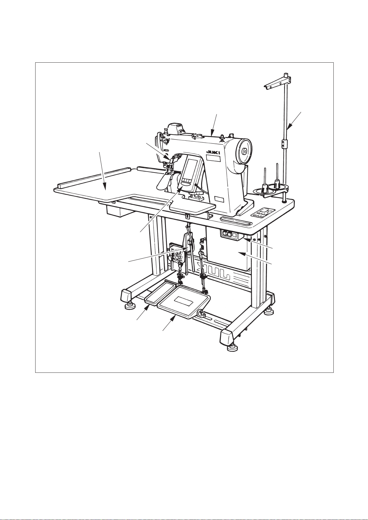
2. CONFIGURATION ..................................................................................2
(1) Sewing machine main unit ................................................................................. 2
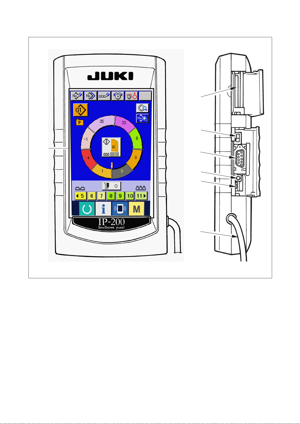
(2) Operation panel ................................................................................................... 3
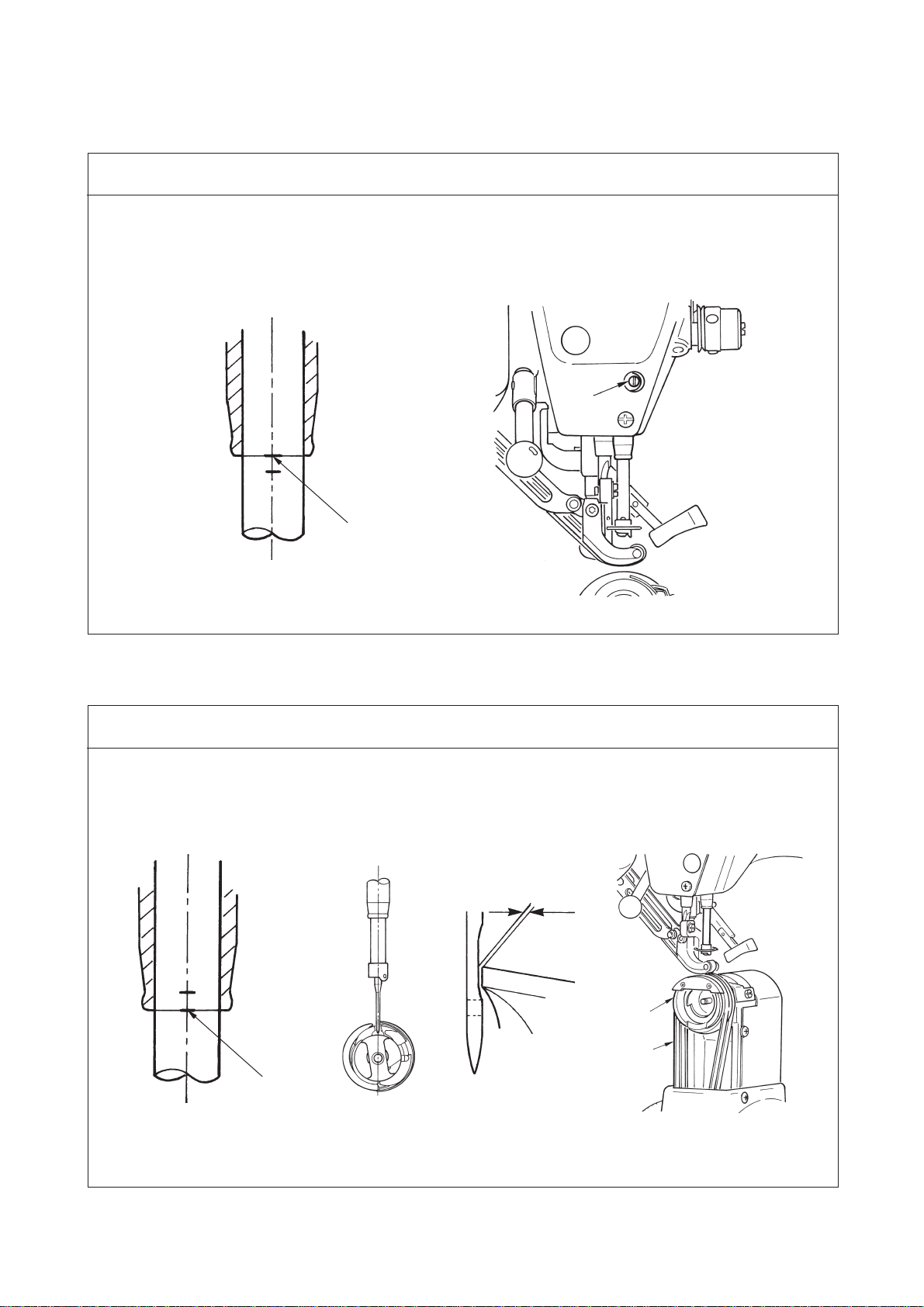
3. STANDARD ADJUSTMENT ...................................................................4
(1) Adjusting the height of the needle bar .............................................................. 4
(2) Adjusting the needle and the hook .................................................................... 4
(3) Removing the main shaft motor and the coupling ........................................... 6
(4) Adjusting the main shaft belt tension ............................................................... 8
(5) Adjusting the hook shaft belt tension ............................................................... 8
(6) Adjusting the feed belt tension .......................................................................... 10
(7) Adjusting the height of the feed foot bar .......................................................... 12
(8) Adjusting the height of the presser foot bar..................................................... 12
(9) Adjusting the amount of alternate vertical movement .................................... 14
(10) Height of the presser screw ............................................................................. 16
(11) Assembling the guide plate .............................................................................. 16
(12) Adjusting the initial position of the auto-lifter................................................ 18
(13) Adjusting the speed of the auto-lifter .............................................................. 18
(14) Adjusting the stroke of the auto-lifter ............................................................. 20
(15) Adjusting the thread trimmer cam ................................................................... 20
(16) Adjusting the initial position of the moving knife .......................................... 22
(17) Adjusting the initial position of the thread trimmer solenoid ....................... 22
(18) Adjusting the position of the moving knife and the counter knife ............... 24
(19) The fixing position of the auxiliary feed motor pulley ................................... 24
(20) The fixing position of the main feed motor pulley .......................................... 26
(21) The fixing position of the thrust collar of AT solenoid ................................... 26
(22) The fixing position of the thread tension shaft collar .................................... 28
(23) Adjusting the height of the feed foot ............................................................... 28
(24) Adjusting the height of the auxiliary feed foot ............................................... 30
(25) Adjusting the height of the presser foot ......................................................... 30
(26) Adjusting the feed eccentric cam .................................................................... 32
(27) Adjusting the assembly of the counter knife guard plate ............................. 32
(28) Replacing procedure of the top feed belt........................................................ 34
(29) Replacing procedure of the bottom feed belt ................................................. 48
4. PARTS TO BE GREASED ......................................................................50
5. SET-UP MANUAL FOR IP-200 ...............................................................52
(1) Connecting procedure of operation panel with external vehicle .................... 52
(2) Re-setup of operation panel ............................................................................... 56
(3) Re-setup of main program.................................................................................. 59
(4) Re-setup of servo program................................................................................. 65
(5) When using smart media other than that which has been packed
together ................................................................................................................ 71

6. INITIALIZING THE BACKUP DATA ........................................................ 72
7. SEWING DATA LIST ............................................................................... 73
8. MEMORY SWITCH DATA LIST ..............................................................76
9. ERROR CODE LIST ............................................................................... 82
10. TROUBLES AND CORRECTIVE MEASURES ....................................87
(1) Mechanical parts ................................................................................................. 87
(2) Electrical parts..................................................................................................... 93
11. CIRCUIT DIAGRAM ..............................................................................104
(1) Block diagram (1/2) ............................................................................................. 104
(1) Block diagram (2/2) ............................................................................................. 105
(2) Head and table/stand circuit diagram................................................................ 106
(3) Main and panel circuit diagram .......................................................................... 107
(4) Power source A circuit diagram ......................................................................... 108
(5) Power source B circuit diagram ......................................................................... 109
(6) Power source C circuit diagram ......................................................................... 110
(7) Motor circuit diagram .......................................................................................... 111
(8) Servo motor circuit diagram ............................................................................... 112
12. VARIOUS PRINTED WIRING BOARDS ............................................... 113
(1) FLT-T p.c.b. ........................................................................................................... 113
(2) FLT-S p.c.b............................................................................................................ 113
(3) PWR p.c.b............................................................................................................. 114
(4) MAIN p.c.b. ........................................................................................................... 114
(5) PANEL p.c.b. ........................................................................................................ 115
(6) DATA p.c.b. ........................................................................................................... 115
13. DRAWING OF THE TABLE ...................................................................116
(1) Slant table ............................................................................................................ 116
(2) Work top table ...................................................................................................... 117
(3) Edge Stopper A ................................................................................................... 118
(4) Edge Stopper B ................................................................................................... 119

−1 −
1. SPECIFICATIONS
Limitation by the amount of alternate vertical movement of presser foot and feed foot
Limitation by stitch length
Max. sewing speed (rpm) Stitch length (mm)
3,500 1.5 to 4.0
2,500 4.1 to 6.0
*1. The maximum sewing speed is limited in accordance with the amount of alternate vertical movement of
presser foot and feed foot, and stitch length.
2. Limitation by the stitch length is automatically limited.
3. Set the limitation by the amount of alternate vertical movement with the memory switch K02.
Max. sewing speed (rpm)
3,500
2,600
2,000
1,600
No.
Specifications
DP-2100
Computer-controlled dry-head, lockstitch, sleeve
setting machine with a multi-program device
3,500 rpm (*1)
Intermittent belt feed by direct drive of stepping motor
Both top and bottom 1.5 to 6 mm
Panel input
0.1mm
30.7mm
DP X 17 #10 to #14
Full-rotary non-lubrication horizontal-axis hook
Bobbin case for full-rotary non-lubrication
horizontal-axis hook
Standard aluminum bobbin
By hand lifter : 5.5 mm, by auto-lifter : 10 mm
3.5 mm (0.2 to 0.3 mm at the time of delivery)
Slot stop position adjustment
Non-lubrication
99 programs
30 steps
Provided
Possible
Smart media
Exclusive grease : 23640204 (500g can)
JUKI grease A : 40006323 (tube of 10g)
106 Kg (head 65 Kg)
MC-650
50Hz / 60Hz
560VA
0 to 40, Less than 90%
Workplace-related noise at sewimg speed
n=3,000 min
-1
:
LPA ≦
84dB(A)
Noise measurement according to DIN 45635-48-A-1
Item
Model
Model name
Max. sewing speed
Feed system
Stitch length
Stitch length adjustment system
Stitch length adjustment minimum resolution
Needle bar stroke
Needle
Hook
Bobbin case
Bobbin
Presser foot lift
Amount of alternate vertical movement of
presser
foot/feed foot Max.
Adjustment of amount of alternate vertical
movement
of presser foot/feed foot
Lubrication
Number of programs that can be inputted
Number of steps that can be inputted (per program)
Data mirroring
Right/left alternate sewing
Data record
Grease
Weight of complete set
Control box model
Power voltage
Frequency
Rated current
Power/power consumption
Operating temperature/humidity
Noise
1
2
3
4
5
6
7
8
9
10
11
12
13
14
15
16
17
18
19
20
21
22
23
24
25
26
27
28
29
30
Amount of vertical movement of feed foot (mm)
Less than 0.3
Not less than 0.3 to 1.5
Not less than 1.5 to 2.5
Not less than 2.5 to 3.5
Amount of vertical movement of presser foot (mm)
(2.7)
(1.5)
(2.5)
(3.5)
3-phase
200V/220V/240V
Single phase
220V/230V/240V
2.6A/2.4A/2.2A 2.8A/2.6A/2.5A

−2 −
2. CONFIGURATION
1 Sewing machine head
2 Operation panel
3 Control box
4 Auxiliary table (WORK TOP TABLE)
5 Power switch
6 Main pedal
7 Auxiliary pedal
8 Thread stand
9Shirring release switch
!0 Knee switch for step changeover
(1) Sewing machine main unit
1
2
3
4
5
6
7
8
9
!0

−3 −
(2) Operation panel
1 Touch panel, LCD display section
2 Smart media slot card (Use with the lid closed.)
3 Slide switch (Unused • OFF)
4 Connector for RS-232C communication
5 Variable resistor for adjusting color LCD screen contrast
6 Connector for external input
7 Cable
1
2
3
4
5
6
7
(Front face) (Right side face)

−4 −
3. STANDARD ADJUSTMENT
(1) Adjusting the height of the needle bar
To align
1
1. Bring the needle bar to its lower dead point, and adjust so that the upper marker line engraved on the
needle bar aligns with the bottom end face of the needle bar lower bushing.
Standard Adjustment
0.04 to 0.1 mm
3
4
(2) Adjusting the needle and the hook
1. Adjust the blade point of hook to the center of needle so that the clearance between the blade point
and the needle is 0.04 to 0.1 mm when the lower marker line engraved on the needle bar aligns with
the bottom end face of the needle bar lower bushing. Then tighten three setscrews in the hook.
* RP hook (dry hook) rolls thread waste or cloth dust, and there is a possibility of breakdown or sewing
trouble. Periodically perform cleaning of the hook.
Standard Adjustment
To align

−5 −
1
2
5
6
Adjustment Procedures Results of improper Adjustment
1. Remove throat plate auxiliary plate 1, hook cover asm. 2and hook
base 3.
2. Turn the handwheel and adjust the lower marker line engraved on the
needle bar to the bottom end face of the needle bar lower bushing.
3. Loosen three setscrews in the hook, adjust the needle to the blade
point, and tighten three setscrews in the hook.
4. Put bottom feed belt 4on hook base 3, and assemble them to the
hook shaft base.
5. Assemble throat plate auxiliary plate 1and hook cover asm. 2.
™
When the clearance is excessively
narrow, the blade point of hook is
damaged, and when it is
excessively wide, stitch skipping
will be caused.
™
Place counter knife guard plate 5
located inside hook base 3to the
inside of counter knife 6since
pull-up trouble will be caused.
1. Turn the handwheel by hand to bring the needle bar to its
lower dead point.
2. Remove the plug of the face plate cover.
3. Loosen needle bar connection setscrew 1to adjust the
height.
4. Tighten needle bar conection setscrew 1, and attach the
plug.
™
Stich skipping or thread breakage
may occur.
Adjustment Procedures Results of improper Adjustment

−6 −
(3)Removing the main shaft motor and the coupling
1. Clearance between main shaft motor 1and coupling 2has to be 0.5 mm.
Standard Adjustment
Flat section
3
2
Screw No. 1 3
0.5mm
Screw No. 1 7
5
6
4
8
1
A
7

−7 −
1. Loosen the respective setscrews in side plate 4, pulley 5and
pulley cover 6, and remove the respective parts.
2. Loosen two setscrews 7in the coupling.
3. Loosen four setscrews 8in the main shaft motor and remove
main shaft motor 1.
4. Loosen two setscrews 3in the coupling.
5. Insert a spacer of 0.5 mm between the end of main shaft motor
1and coupling 2, and tighten setscrews 3in the coupling.
6. When assembling, assemble in the aforementioned order of 3, 2,
and 1 in the reverse order of removing.
™
When setscrews 3and 7in
the coupling are not adjusted to the
flat section of main shaft motor 1
and that of the main shaft :
1. UP-stop position does not
come near to 50˚.
2. Thread is not cut.
Adjustment Procedures Results of improper Adjustment
(Caution) When tightening setscrews 3and 7in the
coupling, assemble so that screw No. 1 in terms of
the rotating direction A of the main shaft should
come to the flat sections of main shaft motor 1
and the main shaft.

−8 −
(4) Adjusting the main shaft belt tension
1. Press in the direction of Awith a load of 19.6 N (2 Kgf), and tighten setscrew 2.
Standard Adjustment
Main shaft belt
(5) Adjusting the hook shaft belt tension
1. The hook shaft belt has to sag 3 mm when the center of hook shaft belt 3is pressed with a load of
1.3N (130gf).
Standard Adjustment
Press the center
1
2
A
3
1
2
1
B

−9 −
Adjustment Procedures Results of improper Adjustment
1. Loosen lock nut 2in belt idler 1.
2. Press belt idler 1in the direction of arrow mark B, and tighten
lock nut 2.
™
When belt tension is excessively
low, the side where the belt is
loosened vibrates and noise
occurs. At the same time, the slip
of hook position occurs, resulting
in needle breakage or damage of
hook.
™
When belt tension is excessively
high, the side where the belt is
tense vibrates. At the same time,
the load to bearing is increased,
and the life of machine is
shortened.
1. Loosen setscrew 2in idler installing plate 1.
2. Press idler installing plate 1in the direction of arrow mark A
with a load of 19.6 N (2 Kgf), and tighten setscrew 2.
™
When belt tension is excessively
low, the side where the belt is
loosened vibrates and noise
occurs.
™
When belt tension is excessively
high, the side where the belt is
tense vibrates with a sharp noise.
Adjustment Procedures Results of improper Adjustment

−10 −
8
8
1
7
4
5
!3
!4
(6) Adjusting the feed belt tension
1. Main feed belt
Adjust so that main feed belt 9sags 3 mm when it is pressed with a finger with a load of 1.3N (130 gf).
2. Auxiliary feed belt
Adjust so that auxiliary feed belt !0 sags 3 mm when it is pressed with a finger with a load of 0.4N (40 gf).
3. Bottom feed belt
Adjust so that bottom feed belt !1 sags 3 mm when it is pressed with a finger with a load of 1.5N (150 gf).
*The standard of the replacing time of the respective belts is one year although it depends on the
frequency of use.
Replace the belt when excessive decrease of feed force or the like is observed.
Standard Adjustment
A
B
B
3
2
6
C
Press the center
6
!1
Press the center
39
2
!0

−11 −
1. Main feed belt
(1) Remove 10 setscrews 8in top feed covers A 1and B 7.
(2) Move tension adjustment plate L 2to the right and left
to adjust the tension. Move to the right (direction A) to
increase the tension, and to the left to decrease it.
2. Auxiliary feed belt
(1) Move tension adjustment plate S 3to the right and left
to adjust the tension. Open both sides (direction B) to
increase the tension, and close both sides to decrease it.
3. Bottom feed belt
(1) Remove throat plate auxiliary plate 4, hook cover asm.
5, frame cover !3 and bottom feed cover !4.
(2) Move bottom feed tension plate 6to the right and left to
adjust the tension. The tension is increased in the
direction of C.
™
If the tension is not proper, shirring
trouble due to feed pitch error will
be caused.
Adjustment Procedures Results of improper Adjustment

−12 −
(8) Adjusting the height of the presser foot bar
1. Adjust the clearance between the bottom face of
presser foot 4and needle hole guide 7to 0.1 mm.
(Refer to the previous item (7) Adjusting the
height of the feed foot bar.)
Standard Adjustment
152
6
3
Be careful of parallel
4
3
(7) Adjusting the height of the feed foot bar
1. Adjust the clearance between top and bottom feed belts to 0.1 mm.
Standard Adjustment
0.1 mm
4
7
7
0.1mm
4

−13 −
1. Height of the feed foot bar
(1) Bring the needle bar to its upper dead point.
(2) Remove plug 1.
(3) Loosen feed foot bar connection clamp screw 2.
(4) Move feed foot 3up or down and adjust the clearance
between top feed belt and bottom feed belt to 0.1 mm.
Then tighten feed foot bar connection clamp screw 2.
™
When the clearance is larger than
0.1 mm, feed force is deteriorated.
™
Clearance between top and bottom
feed belts is 0.1 mm. If the
clearance is widened more than the
specified value, components
interfere with each other.
™
When tightening feed foot bar
clamp screw 2, take care of the
parallel between feed foot 3and
presser foot 4.
Bend of cloth or feed trouble will
be caused.
Adjustment Procedures Results of improper Adjustment
1. Height of the presser foot bar
(1) Bring the needle bar to its lower dead point.
(2) Remove face plate 5.
(3) Loosen presser foot bar connection clamp screw 6.
(4) Adjust the clearance between the bottom face of presser
foot 4and needle hole guide 7to 0.1 mm, and tighten
presser foot bar connection clamp screw 6.
(Refer to the previous item (7) Adjusting the height of
the feed foot bar.)
™
When the clearance is widened,
feed force is deteriorated.

−14 −
(9) Adjusting the amount of alternate vertical movement
1. State of feed foot and presser foot at the time of delivery
Standard Adjustment
6
5
4
4
B
1
(Caution) When changing the amount of alternate vertical movement, change max. sewing speed.
When it is not changed, components breakage or damage occurs and the life of the
machine is excessively shortened.
2. Relation between amount of alternate vertical movement and max. sewing speed
Cam rod position Top feed arm lowest position
Amount of alternate vertical movement of feed foot 0.2 to 0.3 mm
Clearance at lower dead point of feed foot 0.1mm
Amount of alternate vertival movement of presser foot Approximately 2.7 mm
Clearance at lower dead point of presser foot 0.1mm
Amount of vertical
movement of feed foot (mm)
Amount of vertica
movement of presser foot (mm)
Max. sewing speed (rpm)
1
Less than 0.3
2.7
3,500
2
Up to 1.5
1.5
2,600
3
Up to 2.5
2.5
2,000
4
Up to 3.5
3.5
1,600
Hole A 3
2
Be careful of parallel

−15 −
1. Turn the handwheel and bring the needle bar to its lower dead
point.
2. Adjust the position of cam rod 1to the lowest position of top
feed arm 2.
3. Remove stopper plug 6, insert a hexagonal wrench key from
hole A, and loosen top feed arm clamp screw 3.
/Feed foot 4moves downward. Adjust so that clearance B
between top and bottom belts becomes 0.1 mm.
(Range : 0.1 to 1.0 mm)
(It is the premise that (7) Adjusting the height of the feed foot bar
has been performed.)
4. Turn presser foot lever 5, raise feed foot 4, and insert a
spacer so that the clearance between top feed belt and bottom
feed belt becomes 0.2 to 0.3 mm.
5. Tighten top feed arm clamp screw 3.
6. Turn presser foot lever 5and remove the spacer.
™
When the clearance is widened,
feed force is deteriorated at high
speed.
™
When the clearance is widened,
noise or vibration is increased at
high speed.
™
When the clearance is excessively
narrow, efficiency of rotation of
material is deteriorated.
Adjustment Procedures Results of improper Adjustment

−16 −
(10) Height of the presser screw
1. Adjust the height of top feed spring adjusting screw 1to 30 ±0.3 mm from the machined plane of
frame.
2. Adjust the height of presser spring regulator 2to 19 ±0.3 mm from the top surface of spring base 3.
Standard Adjustment
(11) Assembling the guide plate
1. Roller guide 1has to always receive roller 2when roller moves 2up and down.
2. Assemble presser foot guide plate 3so that presser foot shaft connection 4smoothly moves up
and down.
Standard Adjustment
1
2
5
3
4
30 ±0.3 mm
19 ±0.3 mm
5
1
4
6
3
2
Other manuals for DP-2100
3
Table of contents
Other JUKI Sewing Machine manuals

JUKI
JUKI MH-1410 User manual

JUKI
JUKI HZL-F series User manual

JUKI
JUKI DDL-5550 User manual

JUKI
JUKI NA-11UT Series User manual

JUKI
JUKI MO-2000QVP User manual

JUKI
JUKI DLU-5494N-7/IP-100C User manual

JUKI
JUKI MO-104N User manual

JUKI
JUKI LU-1510N Quick start guide

JUKI
JUKI PS-800-12080 User manual

JUKI
JUKI TL-2200QVP Mini User manual

JUKI
JUKI MO-6704D User manual

JUKI
JUKI DDL-8700-7 User manual

JUKI
JUKI LK1903B/BSS302 User manual

JUKI
JUKI HZL-35Z User manual

JUKI
JUKI HZL-F series User manual

JUKI
JUKI LS-1340 User manual

JUKI
JUKI SC-910N User manual

JUKI
JUKI MO-114D User manual

JUKI
JUKI DLN-9010A-SH User manual

JUKI
JUKI HZL - 355Z Series User manual