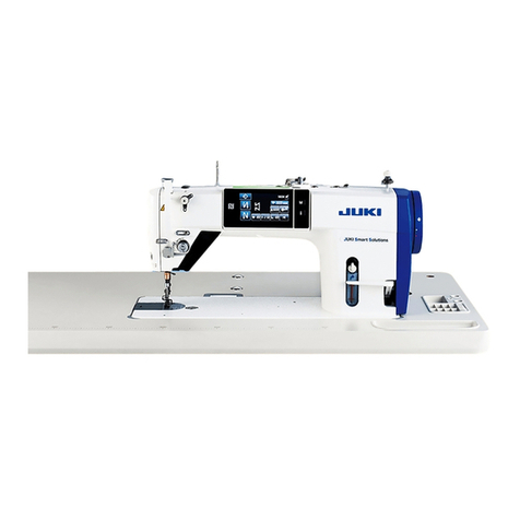
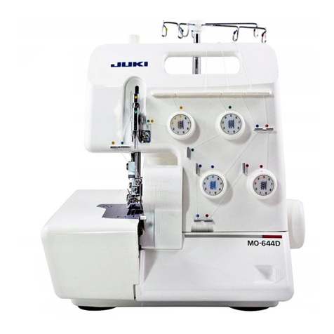
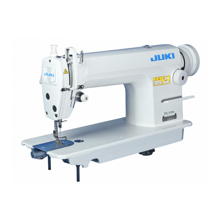
JUKI HZL-12Z User manual

Page 1/19
Original issue
Jun. 2012
Service Manual
HZL-12Z
Model
HZL-12Z

Page 2/19
Original issue
Jun. 2012
Service Manual
HZL-12Z
Model
TABLE OF CONTENTS
1. DISASSENBLING OUTER PARTS
2. FEED DOG HEIGHT
3. NEEDLE HEIGHT
4. HOOK OF NEEDLE THREADER
5. PRESSERFOOT HEIGT
6. NEEDLE POSITION, STRAIGHT STITCHING
7. NEEDLE SIDE MOTION
8. FEED DOG CLEARANCE TO NEEDLE PLATE
HOLE
9. NEEDLE TIMING TO SHUTTLE
10. NEEDLE CLEARANCE TO SHUTTLE
11. SHUTTLE SHAFT RATTLE
12. THREAD TENSION
13. ADJUSTING MOTOR BELT TENSION
14. ADJUSTING BUTTONHOLE PITCH BALANCE
*The parts in the pictures can be looked differently as what they are.

Page 3/19
Original issue
Jun. 2012
Service Manual
HZL-12Z
Model
1.DISASSENBLING OUTER PARTS (1)
(1) Removing a face cover
Take out 2 screws and remove a face cover.
(2) Removing a front cover
1. Take out 2 screws on a bottom surface.
2. Take out 4 screws of a back face.

Page 4/19
Original issue
Jun. 2012
Service Manual
HZL-12Z
Model
1. DISASSENBLING OUTER PARTS (2)
3. Take out 2 screws of a thread guide plate.
Loosen one of them and take off thread guide plate.
4. Take out 2 screws and take off a switch cover.
5. Remove front and back covers with a small screw driver.
Just loosen it.

Page 5/19
Original issue
Jun. 2012
Service Manual
HZL-12Z
Model
1. DISASSENBLING OUTER PARTS (3)
6. Extract a length control dial
7. Take off a side-on connection putting a hand in a hole of length control dial.
Take off a connection of a needle bar.
8. Take off a front cover.(Including a shuttle cover)
Disconnect this connector, and you can
take off a front cover.

Page 6/19
Original issue
Jun. 2012
Service Manual
HZL-12Z
Model
1. DISASSENBLING OUTER PARTS (4)
(3) Taking off a back cover.
1. Pull out a switch cover after taking out screws.
2. Pull out a back cover backwards and take it off.
*It is possible to do test sewing by attaching a thread guide plate(set).

Page 7/19
Original issue
Jun. 2012
Service Manual
HZL-12Z
Model
2. FEED DOG HEIGHT
〔Checking〕
1. Set the stitch length control at “maximum”.
2. Turning a hand wheel by hand, bring up feed dogs totheir top position.
3. Check if feed dog height is 0.89 – 1.09 mm from upper surface of a needle plate.
〔Adjustment〕
1. Under checking condition, while pushing a feel lifting lever(1) against a pin(3) of a
shuttle adjust lever(2), correct feed dog height by loosening 2 screws(4) and
turning an adjusting nut(5).
Lift a screw driver down(Clockwise direction) →Feed dogs become high
Lift a screw driver up(Anticlockwise direction) →Feed dogs become low
0.89 - 1.09mm
1
2
3
4
5

Page 8/19
Original issue
Jun. 2012
Service Manual
HZL-12Z
Model
3. NEEDLE HEIGHT
〔Checking〕
1. Set the zigzag width at “maximum”.
2. Turning a hand wheel by hand, bring a needle to its right hand and lowest position.
Then bring it to the center of a needle plate eyehole by turning the zigzag width
control dial.
3. Check if height of a needle tip is the same level as bottom surface of a gage.
* Bottom surface of a gage is 11.17mm from the centre of a shuttle.
* Top surface of a gage is 11.47mm from the centre of shuttle.
〔Adjustment〕
1. Remove a face cover.
2. Remove a thread guide plate(set).
3. Loosen a screw(2) of a needle bar clamp(1), and correct needle bar height by sliding
it up and / or down.After adjustment, tighten a screw(2) securely.(When tightening a
screw, a needle must be facing front.)
11.17 - 11.47mm
from center of a shuttle race
Needle position is center
and lowest
1
2

Page 9/19
Original issue
Jun. 2012
Service Manual
HZL-12Z
Model
4. HOOK OF NEEDLE THREADER
〔Checking and adjustment〕
Adjust position of a hook by using one of accessories, a small screw driver when
a hook is not aligned.

Page 10/19
Original issue
Jun. 2012
Service Manual
HZL-12Z
Model
5. PRESSER FOOT HEIGT
〔Checking〕
1. Raise a presser foot lifter.
2. Lower feed dogs below the upper surface of a needle plate by turning a hand
wheel.
3. Check if clearance between a presser foot and a needle plate is approx. 5.5 mm.
〔Adjustment〕
1. Raise a presser foot lifter.
2. Loosen a screw(2) of a presser bar bracket(1), and correct presser bar(3)
height by sliding it up or down.
3. After adjustment, tighten a screw(2) securely, keeping a presser foot in parallel
with feed dog direction.
5.5mm
1
2

Page 11/19
Original issue
Jun. 2012
Service Manual
HZL-12Z
Model
6. Needle position, Straight stitching
〔Checking〕
1. Set the zigzag width at “0”.
2. Turning a hand wheel by hand, bring a needle to its lowest position.
3. Check if a needle comes to align with dent mark at the left end of a needle plate
eyehole, at this needle position.
〔Adjustment〕
1. Remove a face cover.
2. Remove a thread guide plate.
3. Loosen a screw(3) connecting a zigzag guide bar(2) to a needle bar support(1),
and correct needle position by moving the support(1).
After adjustment, tighten a screw(3).
1
2
3

Page 12/19
Original issue
Jun. 2012
Service Manual
HZL-12Z
Model
7. NEEDLE SIDE MOTION
〔Checking〕
1. Set the zigzag width at “Maximum”.
2. Turning a hand wheel by hand, observe needle movement from its right hand bottom
position upward through a needle plate eyehole.
3. A needle should not start its leftward movement until it comes up 3-4mm. above the
upper surface of a needle plate.
〔Adjustment〕
1. Loosen 2 screws(2) of a worm gear(1) on an upper shaft.
2. Holding a gear(1), turn a hand wheel and adjust set angle of a gear to the upper
shaft.
Needle side motion too early Turn a hand wheel towards you.
Needle side motion too late Turn a hand wheel away from you.
*During adjustment, use only one screw toset a gear.
3. After adjustment, tighten 2 screws(2) at worm gear(1).
1
2
Needle plate

Page 13/19
Original issue
Jun. 2012
Service Manual
HZL-12Z
Model
8. FEED DOG CLEARANCE TO NEEDLE PLATE HOLE
〔Checking〕
1. Set the stitch length control at “maximum”.
2. Turning a hand wheel by hand, check and see if clearance(a) between a front edge
of feed dogs and that of a needle plate hole at the extreme front end position of feed
dogs, and clearance(b) between a rear edge of feed dogs and that of a needle plate
eyehole at the rear end position of feed dogs, are approximately the same. (It should
be a=b.)
〔Adjustment〕
1. Turning hand wheel by hand, bring feed dogs to their front end position.
2. Loosen screw(3) setting a feed rocking arm(2) to a feed rocking shaft(1), and correct
condition (a=b).
3. Tighten a screw(3) securely after adjustment.
1
2

Page 14/19
Original issue
Jun. 2012
Service Manual
HZL-12Z
Model
9. NEEDLE TIMING TO SHUTTLE
[Attention] Before proceeding to this section, 3. NEEDLE HEIGHT must be checked first.
〔Checking〕
1. Remove a bobbin case and a shuttle race cover from a shuttle race.
2. Set the zigzag width at “maximum”.
3. Turning a hand wheel by hand, bring up a needle from its right hand and lowest
position, until a shuttle hook point comes to align with left side of needle. At this
position, check if a shuttle hook point is 1.0 – 1.5 mm above the upper edge of a
needle eye(A).
〔Adjustment〕
1. Loosen screws(1) of a shuttle adjust lever(2), and correct the timing by moving a
lever(2) towards left or right, while pressing a lever(2) against a shuttle drive arm (4)
to ensure positive engagement of projection(3) on the back of a lever(2) with mating
eyehole on a shuttle drive arm(4).
Timing too early →Move an adjust lever(2) towards right.
Timing too late →Move an adjust lever(2) towards left.
2. After adjustment, tighten screws(1).
A : 1.0 –1.5mm
1
2 3
4

Page 15/19
Original issue
Jun. 2012
Service Manual
HZL-12Z
Model
10. CLEARANCE BETWEEN NEEDLE AND
SHUTTLE HOOK POINT
〔Checking〕
1. Remove a bobbin case and a shuttle race cover from a shuttle race.
2. Set the zigzag width at “maximum”.
3. Turning a hand wheel by hand, bring up a needle from its right hand and lowest
position, until a shuttle hook point comes to align with left side of needle. At this
position, check if clearance between a shuttle hook point and a needle plate
eyehole is 0 – 0.1 mm.
〔Adjustment〕
1. Remove outer covers.
2. Loosen screws(2) of a shuttle race(set)(1) and adjust the position.
Fix a gage and conform needle plate hole’s position to a boss’.
3. Check if a boss of a gage goes up and down smoothly.
4. Tighten screws(2) after the position is fixed.
0 - 0.1mm
1
2
Gage
A boss of a gage comes out of a needle
plate eyehole

Page 16/19
Original issue
Jun. 2012
Service Manual
HZL-12Z
Model
11. SHUTTLE SHAFT RATTLE
< Checking the engaging of a shuttle shaft and a rack>
〔Checking〕
1. Make sure that there is no rattle in ashuttle shaft.
〔Adjustment〕
1. Loosen 2 screws(2) of a roller board.
2. Adjust the engaging of a rack(4) and a shuttle shaft gear(5) by moving a roller(3) up
and down.
3. Make sure not to make an upper torque heavy by adjusting engaging.
4. Tighten up 2 screws(2) after adjustment.
Make sure that there is no rattle in the
directions as an arrow indicates.
1 2 4 3 5

Page 17/19
Original issue
Jun. 2012
Service Manual
HZL-12Z
Model
12. THREAD TENSION
〔Checking〕
1. Set the length control dial at “5”.
2. Check tension number by putting polyester thread #60 through tension plates
and pulling it.
3. Keep 22 - 28 g at the tension of a dial.
*The tension of a bobbin case should be 22 - 28 g.
*Check the balance of top thread and bobbin thread at zigzag sewing for test.
〔Adjustment〕
1. Remove a face cover.
2. Keep the dial position in your mind.
3. Adjust tension as prescribed by turning a DT pressure adjusting gnat.
Turn an adjusting gnat inclockwise direction →Tension becomes stronger
Turn an adjusting gnat inanticlockwise direction →Tension becomes weaker

Page 18/19
Original issue
Jun. 2012
Service Manual
HZL-12Z
Model
13. ADJUSTING MOTOR BELT TENSION
〔Checking〕
1. Remove a face cover.
2. When pushing between an upper shaft of a belt and a motor at 200 g, loosen 2
gnats(1) as it bows 7mm.
3. After adjustment, tighten 2 gnats(1).
1

Page 19/19
Original issue
Jun. 2012
Service Manual
HZL-12Z
Model
14. ADJUSTING BUTTONHOLE PITCH BALANCE
*Adjust the length control dial among indicated range for BH sewing.
*It is possible to change forward pitch with length control dial in this model. Follow the
following directions to change backward pitch though it is usually fixed.
1. Adjust backward pitch by turning a screw(1). When not removing a face cover, put
in a screw driver from an eyehole of aface cover top and turn a screw(1).
Turn it in clockwise direction →Backward pitch becomes bigger
Turn it in anticlockwise direction →Backward pitch becomes smaller
2. Adjust backward pitch as follows.
10 - 15 stitches in 5 mm
backward
5mm
1 2
Other manuals for HZL-12Z
2
Table of contents
Other JUKI Sewing Machine manuals

JUKI
JUKI MO-70BA User manual

JUKI
JUKI MO-6900G Series User manual
JUKI
JUKI AMB-289/IP-420 User manual

JUKI
JUKI DDL-5550N-7 User manual

JUKI
JUKI LZ-2280N Series Owner's manual

JUKI
JUKI AW-3SD User manual

JUKI
JUKI DDL-9000 User manual

JUKI
JUKI HZL-80 series User manual

JUKI
JUKI MH-380 Owner's manual

JUKI
JUKI L-1 Series User manual

JUKI
JUKI MO-6800S Series Quick start guide

JUKI
JUKI LK-1850 Series User manual

JUKI
JUKI MF-7800/UT25 User manual

JUKI
JUKI DDL-8700 User manual

JUKI
JUKI LK-1903A User manual

JUKI
JUKI DNU-1541-7 User manual

JUKI
JUKI MO-50e User manual

JUKI
JUKI MO-6704DA User manual

JUKI
JUKI MO-134 User manual

JUKI
JUKI DDL-8700-7 User manual