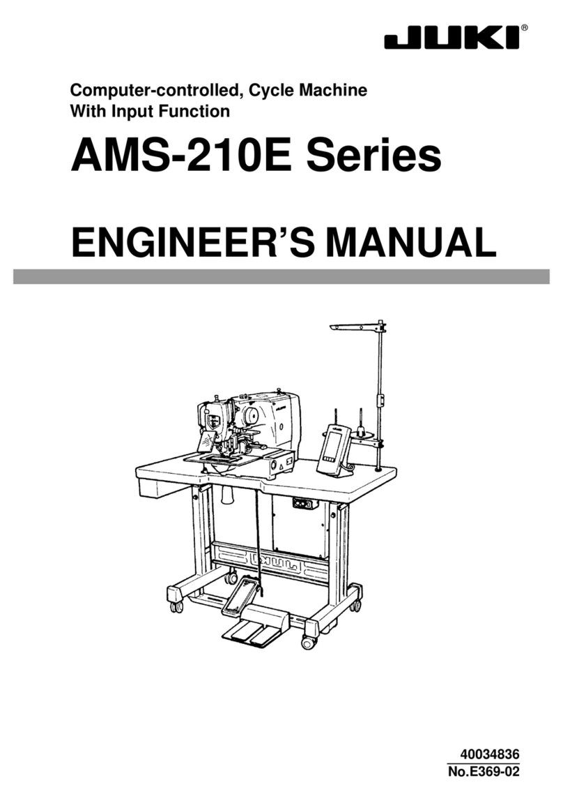
JUKI LK-1941 Quick start guide

29343605
No.E340-01
ENGINEER’S MANUAL
Computer-controlled High Speed Shape-tacking Industrial
Sewing Machine with Full-rotary Three-fold Capacity Hook
LK-1941/LK-1942


PREFACE
This Engineer’s Manual is written for the technical personnel who are responsible for the service and maintenance
of the sewing machine. This manual describes “Adjustment Procedure”, “Results of Improper Adjustment”, and
other functions which are not covered by the Instruction Book intended for the maintenance personnel and
sewing operators at a sewing factory.
All personnel engaged in repair of LK-1941/LK-1942 are required to carefully read Section 2 “Standard
Adjustment” which contains important information on the maintenance of LK-1941/LK-1942.
The “Standard Adjustment” consists of two parts; the former part presents illustration and simplified explanation
for the convenience of reconfirmation of the required adjustment values in carrying out actual adjustment after
reading this manual once; and the latter part provides “Results of Improper Adjustment” in which sewing and/or
mechanical failures, and the correcting procedures are explained for those persons who perform such adjustment
for the first time.
It is advisable to use “LK-1941/LK-1942 Parts Book” together with this Engineer’s Manual.

CONTENTS
1. SPECIFICATIONS ......................................................................................1
2. CONFIGURATION......................................................................................2
(1) Names of main unit................................................................................................. 2
(2) Names of switches on the control box ................................................................. 3
(3) Function of the operation panel key..................................................................... 4
3. ADJUSTMENTS .........................................................................................5
(1) Adjustment of the main shaft components.......................................................... 5
1) Adjusting the play of the main shaft................................................................................................ 5
2) Installing the main motor ................................................................................................................ 5
3) Adjusting the main shaft sensor ..................................................................................................... 7
(2) Adjusting the intermediate presser components (LK-1942)............................... 7
1) Adjusting the position of the intermediate presser cam.................................................................. 7
2) Position of the intermediate presser bar......................................................................................... 9
3) Height of the intermediate presser adjusting screw........................................................................ 9
4) Adjusting the intermediate presser lifting cylinder knuckle ........................................................... 11
(3) Adjusting the wiper components ........................................................................ 11
1) Position of the wiper ..................................................................................................................... 11
(4) Adjusting the hook shaft drive components...................................................... 13
1) Longitudinal position of the main shaft sprocket........................................................................... 13
2) Longitudinal position of the hook driving shaft sprocket ............................................................... 13
3) Backlash of the hook shaft gear ................................................................................................... 13
4) Removing the play of the hook shaft ............................................................................................ 15
5) Height of the needle bar ............................................................................................................... 15
6) Removing the oil shield plate of the hook..................................................................................... 15
7) Needle and the engraved lines..................................................................................................... 17
8) Clearance between the needle and the hook ............................................................................... 17
9) Inner hook stopper........................................................................................................................ 17
10) Timing belt tension ..................................................................................................................... 19
(5) Adjustment of the thread trimmer mechanism components............................ 21
1) Adjusting the thread trimmer cam................................................................................................. 21
2) Adjusting the thread trimmer link stopper screw........................................................................... 21
3) Position of the thread trimmer shaft.............................................................................................. 23
4) Position of the cam installing link stopper..................................................................................... 23
5) Position of the thread trimmer magnet arm .................................................................................. 25
6) Installing position of the moving anf counter knives (For H and G types) .................................... 27
7) Height of the moving and counter knives (For H and G types)..................................................... 27
8) Position of the moving knife and the hot wire plate (For Z type) .................................................. 29
9) Contirmation of operating timing of the moving knife ................................................................... 29
(6) Adjustment of the tension release components................................................ 31
1) Installing position of the tension release notch.............................................................................31
2) Position of the tension release stopper ........................................................................................ 31
(7) Adjusting the sensor components...................................................................... 33
1) Mechanical origin.......................................................................................................................... 33
2) Adjusting the Y origin sensor........................................................................................................ 33
3) Adjusting the X origin sensor........................................................................................................ 35
(8) Adjustment of the feed mechanism components.............................................. 37
1) Adjusting the position of the X motor base ...................................................................................37
2) Adjusting the positions of the X motor and the Y motor ............................................................... 37
(adjusting the backlash of the driving gear) .................................................................................. 37
3) Installing the feed plate support plate........................................................................................... 39
4) Installing the feed plate................................................................................................................. 39
5) Installing the feed bracket............................................................................................................. 41
(9) Adjusting the bobbin thread winder components............................................. 43
1) Position of the bobbin winder driving wheel ................................................................................. 43
(10) Adjusting the presser components .................................................................. 43
1) Adjusting the presser cylinder knuckle ......................................................................................... 43

2) Height of the slider........................................................................................................................ 45
3) Adjusting the speed controller ...................................................................................................... 45
(11) Adjustment of the draw-out device components (For G and Z types) .......... 47
1) Position of the draw-out lever ....................................................................................................... 47
(12) Adjustment of the sewing components............................................................ 49
1) List of the replacement components for the respective types ...................................................... 49
2) Kinds and application of the hook................................................................................................. 50
4. STITCHING PATTERN.............................................................................51
(1) Service Pattern...................................................................................................... 51
(2) Patterns for users................................................................................................. 51
5. MEMORY SWITCH...................................................................................53
(1) Operating method................................................................................................. 56
1) How to start the memory switches................................................................................................ 56
2) How to finish the memory switches .............................................................................................. 60
6. TEST MODE .............................................................................................61
(1) Operating method................................................................................................. 62
1) How to start the test mode............................................................................................................ 62
2) How to finish test mode ................................................................................................................ 63
3) How to check each test program No. ...........................................................................................63
①CP-1 (Input signal check)......................................................................................................... 63
②CP-2 (Origin retrieval) .............................................................................................................. 66
③CP-3 (continuous operation) ....................................................................................................67
④CP-4 (Revolution movement)................................................................................................... 68
⑤ CP-5 (Solenoid, solenoid valve, status output and hot wire output)......................................... 70
⑥CP-6 (Hot wire output) ............................................................................................................. 71
7. EXTERNAL INPUT/OUTPUT ...................................................................72
8. PARTS GREASE OR LOCK-TITE PAINT IS APPLIED ..........................76
9. PRESSER DIMENSIONS .........................................................................78
10. HOW TO USE OPTIONALS ...................................................................79
(1) Needle cooler ........................................................................................................ 79
1) Installing the needle cooler compl. ............................................................................................... 79
2) Installing the solenoid valve.......................................................................................................... 81
3) How to use the needle cooler ....................................................................................................... 83
(2) Thread tension controller No. 3 / inverting clamp device................................. 83
1) Installing the tension controller No. 3 (B50192220B0) ................................................................. 85
2) Installing the solenoid valve.......................................................................................................... 87
3) How to use the tension controller No. 3........................................................................................ 89
(3) Reverse sweeping wiper...................................................................................... 91
1) Installing the reverse sweeping wiper........................................................................................... 91
(4) Thread retaining wiper ......................................................................................... 93
1) Installing the thread retaining wiper.............................................................................................. 93
2) Adjusting the thread retaining wiper ............................................................................................. 93
(5) Feeding frame components for belt (LK-1941) .................................................. 95
1) How to use the feeding frame blank for belt ................................................................................. 95
2) How to use the feed plate blank and the feed plate guide for belt................................................ 95
11. TABLE OF ERROR INDICATION ..........................................................97
12. TROUBLES AND CORRECTIVE MEASURES......................................98
(1) Troubles and corrective measures (Mechanical parts)..................................... 98
(2) Troubles and corrective measures (With regard to sewing) .......................... 100
(3) Electrical components ....................................................................................... 107
13. CIRCUIT DIAGRAM .............................................................................113
This manual suits for next models
1
Table of contents
Other JUKI Sewing Machine manuals

JUKI
JUKI LBH-781 User manual

JUKI
JUKI MO-735 User manual

JUKI
JUKI MOL-254 Quick start guide

JUKI
JUKI TL-2200QVP Mini User manual

JUKI
JUKI IP-100 Quick start guide

JUKI
JUKI AMS-210E-1306 User manual

JUKI
JUKI LS-341N User manual

JUKI
JUKI LK-1850 Series User manual

JUKI
JUKI DDL-9000B-SH Installation and operation manual

JUKI
JUKI LK-1903A User manual

JUKI
JUKI MH-481 User manual

JUKI
JUKI MO-80CB User manual

JUKI
JUKI HZL-F series User manual

JUKI
JUKI MF-7523 User manual

JUKI
JUKI MEB-3200 Series Quick start guide

JUKI
JUKI DDL-8700B-7 User manual

JUKI
JUKI DLN-415 User manual

JUKI
JUKI DP-2100 Quick start guide

JUKI
JUKI MO-50eN User manual

JUKI
JUKI HZL-12Z User manual