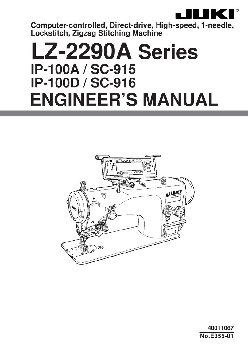
JUKI LU2-4652-B1T User manual

A181E101P01
SINGLE-NEEDLE LOCKSTITCH COMPOUND-FEED
AUTOMATIC UNDERTRIMMER
INDUSTRIAL SEWING MACHINE
MODEL
INSTRUCTION MANUAL
LU2-4652-B1T

PRECAUTION BEFORE STARTING OPERATION
1 Safety Precautions
1 . Whenturningthepoweron,keepyourhandsandngersawayfromtheareaaround/
undertheneedleandtheareaaroundthepulley.
2 . Thepowermustbeturnedowhenthemachineisnotused,orwhentheoperator
leaveshis/herseat.
3 . Thepowermustbeturnedobeforetiltingthemachinehead,installingorremoving
the“V”belt,adjustingthemachine,orreplacingparts.
4 . Avoidplacingngers,hairs,obstacles,etc.nearthepulley,“V”belt,bobbinwinder
wheel,ormotorwhenthemachineisinoperation.Injurycouldresult.
5 . Don’tputngersintothethreadtake-uplevercover,around/undertheneedle,or
pulleywhenthemachineisinoperation.
6 . Ifthebeltcover,thengerguard,and/ortheeyeguardareinstalled,don’toperate
themachinewithoutthesesafetydevices.
2 Precaution before Starting Operation
1 . Ifthemachine’soilpanhasanoilsump,neveroperatethemachinewithoutllingoil
init.
2 . Ifthemachineislubricatedbyadropoiler,neveroperatethemachinewithout
lubricating.
3 . Whenanewsewingmachineisoperated,verifytherotationaldirectionofthepulley
withthepoweron.
(Thepulleyshouldrotatecounterclockwisewhenviewedfromthepulley.)
4 . Verifyvoltageand(singleorthree)phaseindicatedonthenameplateofthemotor.
3 Precaution for Operating Conditions
1 . Avoidusingthemachineatabnormallyhightemperature(35℃orhigher)orlow
temperature(5℃orlower).Otherwise,machinefailuremayresult.
2 . Avoidusingthemachineindustyconditions.
3 . Avoidusingthemachineinconditionslledwithalotofelectricnoisessuchashigh-
frequencywelders.
INTRODUCTION
Thank you very much for purchasing industrial sewing machine.
Please read this instruction manual before operating the sewing machine. Please read also
“Safety Manual”, “Instruction manual for LIMISERVO” and operate the sewing machine
correctly and safely.

CONTENTS
PREPARATION FOR OPERATION ……………………………………………… 1
1Installingtheaircylinderassembly ……………………………………………… 1
2Connectingtheelectriccablestothecontrolbox ……………………………… 1
3Adjustmentofthestitchlengthbeforetrimming ……………………………… 3
4Operationspeedadjustmentofinstantalternatingaircylinder ……………… 4
5Heightadjustmentoftheautomaticpresserfootlifter………………………… 4
6Adjustmentoftheneedlestoppingposition……………………………………… 5
USAGE PRECAUTION ……………………………………………… 6
1Lubrication( 1 ) ……………………………………………………………………… 6
2Lubrication( 2 ) ……………………………………………………………………… 6
3Lubricationcondition………………………………………………………………… 7
4Adjustmentoflubricationtotherotatinghook ………………………………… 7
5Precautionforthebuilt-intypedetector ………………………………………… 7
6Installationofthebeltcover ……………………………………………………… 7
7Precautiononoperation …………………………………………………………… 7
HOW TO USE ……………………………………………… 8
1Installationoftheneedle …………………………………………………………… 8
2Windingofthebobbinthread……………………………………………………… 8
3Selectionofthethread……………………………………………………………… 9
4Threadingoftheneedlethread…………………………………………………… 9
5Adjustmentoffeed(stitch)lengthandbackstitch……………………………… 10
6Settingofthebobbin………………………………………………………………… 10
7Adjustmentoftheneedlethreadguide ………………………………………… 10
8Threadingofthebobbinthread…………………………………………………… 11
9Adjustmentofthebobbinthreadtension………………………………………… 11
:Balanceofthreadstension ………………………………………………………… 11
AAdjustmentoftheneedlethreadtension………………………………………… 11
BAdjustmentofthepresserfootpressure………………………………………… 11
CAdjustmentoftheoutsidepresserfootandinsidepresserfoot ……………… 12
DInstantalternatingswitch ………………………………………………………… 13
EThestopperscrewforadjustingthemaximumalternatingstroke ………… 13
FInstallingthefeedregulatorbracket……………………………………………… 14
GAdjustmentofthealternatingstrokesensingpotentiometer ………………… 14
HTimingbetweentherotatinghookmotionandtheneedlemotion…………… 15
IAdjustmentofthefeeddogheight………………………………………………… 16
J
Relationshipbetweentherotatinghookmotionandthethreadtake-uplevermotion
… 17
KRelationshipbetweentherotatinghookmotionandtheopenermotion …… 17
LRelationshipbetweentheneedlemotionandthefeeddogmotion…………… 18
MSafetyclutch ………………………………………………………………………… 19
NAdjustmentofupperfeedlength(needleside) ………………………………… 20
OAdjustmentofforward/backwardfeedlength ………………………………… 20
PInstallationofthemovableknife…………………………………………………… 21
QInstallationpositionofthethreadtrimmercam………………………………… 22
RAdjustmentofthethreadtrimmercam ………………………………………… 22
SAdjustmentofthethreadtensionreleasing……………………………………… 23
T
Adjustmentofmeshingpressurebetweenthemovableknifeandthexedknife
… 24
USharpeningofthexedknife ……………………………………………………… 24
SPECIFICATIONS ……………………………………………… 25
1 Installing the air cylinder assembly
( 1 ) Aligntheaircylinderassemblytothebackofthearmasshownbelowandthentthedrivinglink
intothepin.
Fitadrivinglinkbetweenthenylonwashers.
( 2 ) Installtheaircylinderassemblyonthebackofthearm.
Tightenthebracketandthebackofthearmwiththeenclosedbolt.
2 Connecting the electric cables to the control box
Connectwiresandpipesasfollows.
( 1 ) Installthesolenoidvalveandthelterregulatorassembly①withinthereachoftheurethanetube
/cordunderthetable.
( 2 ) Installtwoattachedelbowunions②,③ontherearcoverlocatingatthebackofthearm.
( 3 ) Arrangepipingbyurethanetubesbetweentheupperelbowunion②installedbystep( 2 ) andthe
portB( ④ B )oftheupperpresserfootliftersolenoidvalve④,andbetweenthelowerelbowunion
③andtheportA( ④ A ).
( 4 ) Connecttheconnecter⑤ofthepresserbarliftersolenoidvalve④tothepresserfootlifter
connectoronthecontrolbox.
( 5 ) Connecttheurethanetube⑥fromthetopofthesewingmachinetotheportA( 7 Ⓐ ) ofthe
instantalternatingsolenoidvalve⑦.
( 6 ) Connectthe3-pinconnector⑧ofthesewingmachineconnectorandtheconnectoroftheinstant
alternatingsolenoidvalve⑦.
( 7 ) Whenthekneeswitch⑨issubstitutedfortheinstantalternatingswitch,connectthe2-pin
connector⑩suppliedasanoptionBtothekneeswitch.
Drivinglink
Nylon
washer
Bracket
Backofthearm
Bolt
Aircylinderassembly
Pin
PREPARATION FOR OPERATION
—1 —

( 8 ) Connectbyurethanetubebetweentheupperpartelbowunions⑪installedontheaircylinder
assemblyandportAofthesolenoidvalveassembly⑬.
Similarly,connecttheurethanetubebetweenlowersideofelbowunions⑫andportBofthe
solenoidvalveassembly.
( 9 ) ConnecttheairsupplysourcetotheINportofthelterregulator①.
(10)Tietogetherurethanetubesandcordswithattachedbindingbands.
Note:Setthestandardairpressureoftheregulatorto0.4MPa(4kgf/cm2).
⑥④Bport ⑬Bport
⑬Aport
④Aport
⑦Aport
INporttotheair
supplysource
Kneeswitch
LF-FM-CFT
(Option)
①
Urethanetube
OPTIONBOPTIONAF・L S.M
⑪
⑫
②
③
⑤
⑨
⑩
⑧
Aircylinderassembly
PREPARATION FOR OPERATION
—2 —

3 Adjustment of the stitch length before trimming
Dependingonsewingconditions,thestitchimmediatelybeforetrimmingmaynotbeformedcorrectly.
Thismaycausethetrimmedtaillengthtobelong.
Inthiscase,adjustthelengthofthestitchimmediatelybeforethetrimmingpositiontoensurethata
properstitchisformed.Asreference,thestandardstitchlengthis1to2mm.Thelengthofthestitch
immediatelybeforetrimmingcanbeadjustedbymovingthepositionoftheknuckletotheair
cylindershaftup/down.Adjustwiththefollowingmethods.
( 1 ) Loosenthenutontheknuckle.
( 2 ) Rotatetheaircylindershaft.
Adjustthepositionoftheknuckletotheair
cylindershaft.
( 3 ) Thestitchimmediatelybeforetrimmingisas
follows.
・Duringforwardstitching:
Lookingfromabove,turntheshaft
clockwisetochangetoreversestitching.
・Tooshortduringreversestitching:
Lookingfromabove,turntheshaft
clockwise.
・Toolongduringreversestitching:
Lookingfromabove,turntheshaft
counterclockwise.
Thestitchlengthchangesabout1mmwhen
theshaftisrotatedonce.
Inthepositionoftheknucklewhenshipping,
dimensionAbetweenthelowersurfaceofthe
aircylinderandtheuppersurfaceofthe
knuckleis22mmliketherightgurewiththe
aircylinderdrawnin.
A
Shaft
Nut
Knuckle
PREPARATION FOR OPERATION
—3 —

4 Operation speed adjustment of instant alternating air cylinder
( 1 ) Toadjustthespeedoftheaircylinderatthemaximuminstantalternating,adjustthehandle①
withplatedlocknutonthedualspeedcontrolleroftheinstantalternatingsolenoidvalve(lower
side).
( 2 ) Toadjustthespeedoftheaircylinderattheinstantalternatingreturn,adjustthehandle②with
theblackcoloredlocknutonthedualspeedcontrolleroftheinstantalternatingsolenoidvalve(lower
side).
5 Height adjustment of the automatic
presser foot lifter
Thepresserfootlifterheightattheautomaticpresser
canbeadjusted.
( 1 ) Removethetopcover.
( 2 ) Slidethestopperplateonthepresserfootlifterair
cylinderupanddowntoadjust.
①
②
Stopper
Backofthearm
PREPARATION FOR OPERATION
—4 —

PREPARATION FOR OPERATION
6 Adjustment of the needle stopping position
1 . Adjustment of “UP” position
Whenthepedaliskickeddownbyheel,themachinestopsat“UP”position.
Ifmarksdeviatelargerthan3mm,adjustasfollows.
( 1 )Disconnecttheplug(12pins)ofcablefromthemachinehead.
( 2 )Runthemachineandstopat“UP”position.
( 3 )Whileholdingthepulley,insertthe“Adjustingtool”inthehole Ⓐ,thenturnthetool.
2 . Adjustment of “Down” position
Whenthepedalis“Neutral”themachinestopsat“Down”position.
Ifmarksdeviatelargethan5mm,adjustasfollows.
( 1 )Disconnecttheplug(12pins)ofcablefromthemachinehead.
( 2 )Runthemachineandstopat“Down”position.
( 3 )Whileholdingthepulley,insertthe“Adjustingtool”inthehole Ⓑ,thenturnthetool.
3 . Conrmthestopoperation,thensettheplug(12pins)comingfromthemachineheadintothe
receptacle.
Timingmark
Whitemark
Blackmark
Upposition
Downposition
Adjustingtool
UP
later
earlier
DOWN Timingoftheneedle
Ⓐ
Ⓑ
—5 —

MC70M :Specific gravity (15℃) = 0.86 (g/cm3)
2
arrows in the below figure.
For oil, use“ MC70M” specified by our company.
Oil level should be periodically checked. If oil level
Fill the oil reservoir with oil up to“ H” mark.
is found below“ L” level replenish oil to“ H” level.
1
USAGE PRECAUTION
Oillevelmark
Lubrication (2)
Lubrication (1)
1
※Refer
:Viscosity (40℃) = 10.9 (mm2/s)
When a new sewing machine is used for the
first time, or sewing machine left out of use for
considerably long time is used again, replenish a
suitable amount of oil to the portions indicated by
—6 —

5 Precaution for the built-in type detector
1 . Sincetheopticaltypedetectingelementisusedinthedetector,preventdustoroilfromstickingto
thedetectingplatewhenthesewingmachinepulleyisremovedforadjustment.
Iftheyhavestuck,wipethemowithsoftclothcarefullysothatthesurfaceisnotscratched,do
notletoilpermeatetheclearanceonthedetectingplate.
2 . Incaseofdisconnectionofthepositiondetectorconnector,runningothebeltorcomplete
constraintandoverload,themotorisautomaticallyturnedoafterpredeterminedtimetoprevent
burningofthemotor.(However,incaseofhalf-constraintandoverload,thepowermaynotbe
turnedo.)Afterthefailureiseliminated,thenormaloperationisresumedbyturningothepower
oncethenturningonagain.
Thesameoperationoccursforthedetectormalfunctionorthelinebreakage.
6 Installation of the belt cover
1 . Installthebeltcoveronthemachinesideforsafety.Refertotheprovidedinstructiondocument
containedinthesamepackage.
2 . Installthebeltcoveronthemotorsideforsafety.
7 Precaution on operation
( 1 ) Whenthepoweristurnedonoro,keepfootawayfromthepedal.
( 2 ) Itshouldbenotedthatthebrakemaynotworkwhenthepowerisinterruptedorpowerfailure
occursduringsewingmachineoperation.
( 3 ) Sincedustinthecontrolboxmightcausemalfunctionorcontroltroubles,besuretokeepthe
controlboxcovercloseduringoperation.
( 4 ) Donotapplyamultimetertothecontrolcircuitforchecking,otherwisevoltageofmultimeter
mightdamagesemiconductorcomponentsinthecircuit.
3 Lubrication condition
Seedrippingofoilthroughtheoilsightwindowto
checkoilingconditionduringoperation.
4 Adjustment of lubrication to the
rotating hook
USAGE PRECAUTION
Oilsightwindow
Adjustingscrew
IncreaseDecrease
Nut
—7 —

1 Installation of the needle
Note: Before installing the needles, be sure to turn o the power.
HOW TO USE
Longgroove
leftside
2 Winding of the bobbin thread
Note: When bobbin thread is wound, keep the presser foot lifted.
Adjustment ●Tension of wound thread Slackwindingisrecommendedforpolyesterthreadand
nylonthread.
●Conically wound thread Movethethreadguidetowardsmallerdiameterofwound
threadlayer.
●Amount of wound thread Loosenthewindingamountadjustmentscrewtodecrease
threadwindingamountandtightenthescrewtoincrease
threadwindingamount.
Windingtension
adjustmentnut
Evenwinding
amountof80%
offullcapacity
Windingamount
adjustmentscrew
Threadguide
—8 —

HOW TO USE
①
Threadtension
releasingbutton
③
②
④
⑤
⑥
⑦
⑧
⑩
⑪
⑫
⑬
⑭
⑨
3 Selection of the thread
Itisrecommendedtouse“S”twistthreadintheleftneedle(viewed
fromfront),and“Z”twistthreadintherightneedle.
Whendiscriminateuseofneedlethreadsisimpossible,use“Z”twist
threadinboththeneedles.
Forbobbinthread,“S”twistthreadaswellas“Z”twistthreadcanbe
used.
4 Threading of the needle thread
1 . Passeachneedlethreadthroughthreadguide(A).
Note:Whenthinslipperythread(polyesterthreadorlament
thread,etc.)isused,
Passthethreadthroughthreadguide(B)aswell.
2 . Withthethreadtake-upleverlocatedattheuppermostposition,
passeachneedlethreadintheordershowninthefollowinggure.
Note:Pushingtheneedlethreadtensionreleasingbuttonshown
inthegurebelowopensthesauceroftheneedlethreadtension
adjuster,andtheneedlethreadcaneasilypulledout.
Stwistthread
Ztwistthread
A B A AB
—9 —

5 Adjustment of feed (stitch)
length and backstitch
●Adjustmentoffeed(stitch)length…Adjustfeed
lengthbyturningthefeedlengthsettingdial
whilepushingPUSHlever.
Note:Dependinguponthestitchlength,the
maximumsewingspeedsaredierent.
Withreferringtothespecicationson
page25,pleaseoperatethesewing
machineatthespeedlessthanthe
matchingsewingspeedwiththestitch
length.
●Backstitch…Directionofstitchingcanbe
reversedbydepressingthereversesewing
leverorpushingthetouchbackswitch.
6 Setting of the bobbin
( 1 ) Pullout5cmthreadtailfromthebobbin.
( 2 ) Putthebobbinintothehookinthedirection
asthefollowinggure.
7 Adjustment of the needle
thread guide
Adjusttheneedlethreadguideoftheneedle
threadtensionadjusteraccordingtothefabric,the
thread,andsewingcondition.
Needle
thread
guide
position
Leftside Center Rightside
Fabric Heavy Standard Light
Needle
thread
supply
More Standard Less
HOW TO USE
Touchbackswitch
Feedlengthsettingdial
Reversesewinglever
Bedslide
Hook
Bedslide
Thread
—10 —

8 Threading of the bobbin thread
( 1 ) Putbobbinthreadintotheslit①,passunder
thelug②andextenditabovethebed.
( 2 ) Whileholdingtwoneedlethreadswithyour
lefthand,turnthepulleyonerotationwith
yourrighthand.Thebobbinthreadswill
comeupwhenneedlethreadsareliftedup
asshowninthegure.Needlethreadsand
bobbinthreadsshouldbealignedandled
backwardtogether.
9
Adjustment of the bobbin thread tension
: Balance of threads tension
A
Adjustment of the needle thread tension
Toadjustneedlethreadtension,turnthethread
tensionnut.
Pre-tensionnut
Tighten
Loosen
Tighten
Loosen
Threadtensionnut
B
Adjustment of the presser foot pressure
Adjustthepresserfootpressureaccordingtothe
fabricbyturningthepressureadjustingscrew.
Weaken Strengthen
HOW TO USE
Thread
①
② Opener
Loosen Tighten
Threadtensionscrew
A○
B×
C×
Balancedtension
Tighttheneedlethreadtensionor
loosethebobbinthreadtension
Loosetheneedlethreadtensionor
tightthebobbinthreadtension
—11 —

C
Adjustment of the outside presser
foot and inside presser foot
1 . Adjustment of alternating movement
( 1 ) Thealternatingmovementontheoutside
presserfootandinsidepresserfootcanbe
adjustedbyusingtheadjustingdiallocated
onthetopcover.
( 2 ) Facethedesirednumberprintedonthedial
tothematchingmarklocatedonthetop
cover.
( 3 ) Thenumberprintedonthedialrepresents
thepossibleprotrusionoftheoutsidepresser
footandinsidepresserfootfromthethroat
platewhenthealternatingmovementson
theseareevenlyset.
( 4 ) Ifthealternatingmovementsareevenlyset,
theycanbereadjustedupto2.0to6.0mm.
2 .
To change the balance of the alternating movements
between the outside presser foot and inside presser foot
( 1 ) Forexample,toincreasetheriseoftheinside
presserfoot,anddecreasetheriseofthe
outsidepresserfoot.
①Removetherubberpluglocatedonthetop
cover.
②Turnthepulleyuntiltheoutsidepresserfoot
isslightlyraisedfromthethroatplate.
③LoosenthesetscrewⒶlocatedonthefeed
liftingrockshaftcrank(right).
④Thebuilt-inspringpullsdowntheoutside
presserfootuntilitmakescontactwiththe
throatplate.Then,tightenthesetscrewⒶ.
⑤Thiscompletestheadjustment,i.e.,the
protrusionoftheoutsidepresserfoothas
beendecreasedbyasetdistance.And,the
verticalmotionoftheinsidepresserfoothas
beenincreasedbythatsamedistance.
( 2 ) Asacontrarycase( 1 ) ,todecreasetherise
oftheinsidepresserfoot,andincreasethe
riseoftheoutsidepresserfoot.
First,turnthepulleyuntiltheinsidepresser
footisslightlyraisedfromthethroatplate.
Next,loosenthescrewⒶ.Finally,tightenthe
screwⒶagain.
Thisdecreasestheriseoftheinsidepresser
foot.
Rubber
plug
Matchingmark
Alternatingstrokeadjustingdial
Inside
presserfoot
Outside
presser
foot
2.0to6.0mm
Feedliftingrock
shaftcrank(right)
Rubberplug
Ⓐ
SecondscrewⒶ
Firstscrew
Uppereccentricfeedliftingcam
HOW TO USE
3 .
How to install the upper eccentric feed lifting cam
( 1 ) Turnthepulleyandstopitattheposition
wherethethreadtake-uplevercomestothe
lowest.
( 2 ) Inthiscondition,removetherubberplug
locatedonthearm.Locatethesecondscrew
Ⓐintheuppereccentricfeedliftingcamas
showninthegure.Andtightenit.
—12 —

D Instant alternating switch
Duringthesewingoperation,ifasewingmaterial
hasastep,hittheinstantalternatingswitch,then
thealternatingupanddownmovementinstantly
becomesmuchbiggertogetoverthestep.
Hitonce,ON Thealternatingup
anddownmovement
becomeshighest(It
isadjusted6mmis
thehighestwhen
thesewingmachine
isshippedfromthe
factory).
(LightingLEDlamp)
Hittwice,OFF Thealternatingup
anddownmovement
becomesthenormal
strokecontrolledwith
thealternatingstroke
adjustingdial.
Note1:Thekneeswitchalsocanbeusedasthe
instantalternatingswitch.
2:Italsocanbesetthealternatingupand
downmovementtothehighestonly
whilepressingtheinstantalternating
switch.
E The stopper screw for adjusting
the maximum alternating stroke
Themaximumalternatingstrokecanbeadjusted
withthestopperscrewshownintherightgure.
◎Themaximumalternatingstrokeisxedat6
mmwhenthesewingmachineisshippedfrom
thefactory.
Ifthemaximumalternatingstrokeisrequired
tomakesmaller,takethefollowingprocedures.
Note:Donotsetthealternatingstroketomore
than6.5mm,becauseitmaycausefailure.
1. Setthealternatingstrokeadjustingdialtothe
desirednumberofthestroke.
2. Loosenthenutshownintherightgure.
3. Tightenthestopperscrewuntilithitswiththe
specialscrew.
4. Tightenthenut.
Stopperscrew
Nut
Instantalternatingswitch
Alternatingstrokeadjustingdial
Stopperscrew
Specialscrew
Nut
Redmark
(positionat6mm)
HOW TO USE
—13 —

F
Installing the feed regulator bracket
Ifitisnecessarytodismountandreassemblethe
feedregulatorbracketanditsrelatedparts,install
itasfollows.
Note:Ifthefeedregulatorbracketispoorly
positioned,theresultantalternating
movementsmaybetooshortorlongcausing
defectivemachineoperation.
( 1 ) SetthegapbetweenspecialscrewⒶlocated
ontheregulatorshaftandthesidewallof
themachinearmto42.6mmasillustratedto
theleft.(Usea42.6mmspacerbetweenthese
parts.Thisfacilitatestheoperation.)
( 2 ) Withthefeedregulatorstudheldasexplained
instep( 1 ) above,adjustthefeedregulator
bracket.Thisadjustmentshouldinsureagap
of2.3mmbetweentheperipheryofpinⒷ
locatedonthefeedregulatorbracketandthe
topcoverinstallingfacelocatedonthearm.
TightenscrewⒸ.
G Adjustment of the alternating
stroke sensing potentiometer
(Pleaserefertotheinstructionmanualfor
LIMISERVOXGMFYalso.)
Note:Incaseofmaladjustment,thepropersewing
speedmaynotbeobtained.
( 1 ) Turnothepowerswitch.
( 2 ) RemoveallconnectorsexceptOPTIONB
connector.
( 3 ) Removethetopcoverintheconditionwhich
setthealternatingstrokeadjustingdialfor
scale2.
( 4 ) Turnonthepowerswitch,andthensetthe
operationpanelofthecontrolboxtotheinput
display“V2”attheprogrammingmodeE.
( 5 ) LoosentheslottedboltⒹofthepotentiometer
crank.
Atthistime,becarefulnottogiveany
bendingtorquetothepotentiometershaft.
( 6 ) Fixthedistancebetweenthefeedregulator
shaftspecialscrewⒶandtheinnerwallof
thesewingmachinearm42.6mm.
(Itisrecommendedtousethespacersized
42.6mmforquickxing.)
( 7 ) Turnthepotentiometershaftsothatthe
inputdisplay“V2”indicates280to289.
Feedliftingrock
shaftcrank(right)
Feedregulatorshaft
Feedregulatorbracket
42.6mm
2.3mm
Ⓑ
Ⓐ
Ⓒ
Potentiometer
42.6mm
Ⓓ
Ⓐ
HOW TO USE
( 8 ) TightentheslottedheadboltⒹofthe
potentiometercrank.
( 9 ) Makesureagainthattheinputdisplay“V2”
indicates280to289.Ifthedisplayindicates
thedierentnumberfrom280to289,adjust
thepotentiometershaftagain.
(10) Turnothepowerswitch.
(11) Putthetopcoverbackintheconditionwhich
setthealternatingstrokeadjustingdialfor
scale2.
(12) Connectalltheconnectorsasbefore.
—14 —

H Timing between the rotating
hook motion and the needle
motion
Note:Ifyouremovethepresserfoot,thethroat
plate,andthefeeddog,itmakeseasierto
adjust.
( 1 ) Setfeedlengthto6mm.
( 2 ) LoosenallscrewsⒶ, Ⓑ, Ⓒ.
Note:Becarefulnottodisengagethelarge
gearandthesmallgear.
( 3 ) Lifttheneedlebar2.4mmfromthelowest
position.Refertotimingmarksshowninthe
gure.
( 4 ) Slidethehooksaddlerightandleftsothat
thegapbetweenthetipofthehookandthe
scarfoftheneedleis0.05mmorlower.
( 5 ) TightenscrewsⒶ, Ⓑ.
Note:BecarefulnottoovertightenscrewⒷ.
( 6 ) Slidethelargegearrightandleftsothatthe
tipofthehookpositionisinthecenterofthe
needleandtightenscrewsⒸ.
Note:Checkthelargegearandthehook
saddleisn’tincontactanditsdistanceis
lessthan3mm.
( 7 ) Movethetipofthehooktotheneedleside
byturningthepulley.
( 8 ) Returnthemachineheadtotheoriginal
positionandadjusttheneedleguideposition
sothatitcomeslightlyincontactwiththe
needle.
HOW TO USE
Tipof
thehook
0.05mmorlower
0.05mm
(a)Positionoftheneedlebar:
Thelowestposition
(b)Positionoftheneedlebar:
2.4mmliftedpositionfrom(a)
ScrewⒶ
ScrewⒷ
ScrewⒸ
—15 —

I
Adjustment of the feed dog height
Thefeeddogheightandthepresserfootpressure
mustbeadjustedaccordingtothefabric.
◆ Thefabricwillbedamagedifthefeed
dogextendstoohigh,orifthepresserfoot
pressureistoolarge.
◆ Anevenstitchlengthcannotbeassuredif
thefeeddogistoolow,orifthepresserfoot
pressureistoosmall.
◆ Thefeeddogheightisthepositionwherethe
needleisatthetopposition.
Adjustment of the feed dog height
( 1 ) Leanthemachineheadbackward.
( 2 ) Turnthepulleybyhandandstopitatthe
positionwherethefeeddogrisestothe
maximumheight.
( 3 ) Loosenthefeedbarscrew.
( 4 ) Verticallymovethefeedbar(inthedirection
indicatedbythearrowinthegure)toadjust
ittoanadequateheight.
( 5 ) Afteradjusting,tightenthefeedbarscrew.
The feed dog height is factory-adjusted to 1.0 mm.
HOW TO USE
Throatplate
Feeddog
1.0mm
Feedbar
screw
Feedbar
—16 —

J
Relationship between the rotating
hook motion and the thread take-up
lever motion
Whenthetimingbeltisremovedforreplacement,
etc.,therelationbetweentherotatinghookmotion
andthethreadtake-uplevermotionshouldbe
adjustedasfollows:
( 1 ) Turnthepulleyandstopwhenthethread
take-upleverisliftedtothehighestposition.
( 2 ) Leanthemachineheadbackwardandcheck
thatthearrow(timingmark)putonthe
timingbeltisalignedwiththeblacklineon
thebossoflowershaftbearing.
( 3 ) Ifthetimingmarkisnotinlinewiththe
blackline,removethetimingbeltandinstall
itagaintoadjust.
K
Relationship between the rotating
hook motion and the opener motion
( 1 ) Turnthepulleybyyourhandandstopit
atthepositionwheretheopenerholderis
locatedmostremotelyfromthethroatplate.
( 2 ) CheckthatthegapbetweenthelugⒶand
theopenerisapproximately0.2mm.
( 3 ) Ifthegapistoolargeorsmall,loosenthe
openerholderscrewⒷandadjustpositionof
theopener.
HOW TO USE
Timingbeltpulley
Timingmark(arrow)
Blacklineonbossoflowershaftbearing
Timingbelt
Approx.0.2mm
Opener Openerholder
ⒶScrewⒷ
—17 —
Table of contents
Other JUKI Sewing Machine manuals

JUKI
JUKI AMS-210D User manual

JUKI
JUKI LU-2860V-7 User manual

JUKI
JUKI LBH-780 Series User manual

JUKI
JUKI SC-922 Quick start guide

JUKI
JUKI MO-735 User manual

JUKI
JUKI MO-102 User manual

JUKI
JUKI LK-1910 User manual

JUKI
JUKI LZ-2280N Series Quick start guide

JUKI
JUKI CP-160 User manual

JUKI
JUKI AMS-224EN4530R User manual

JUKI
JUKI IP-100 User manual

JUKI
JUKI MB-1800B User manual

JUKI
JUKI LBH-1795AN User manual

JUKI
JUKI HZL-27Z User manual

JUKI
JUKI MS-1190 User manual

JUKI
JUKI MF-7500D Series User manual

JUKI
JUKI DDL-9000C-S Series Quick start guide

JUKI
JUKI LZ-2290A-SS-7 Quick start guide

JUKI
JUKI MO-6900C Series User manual

JUKI
JUKI LBH-1790AN User manual