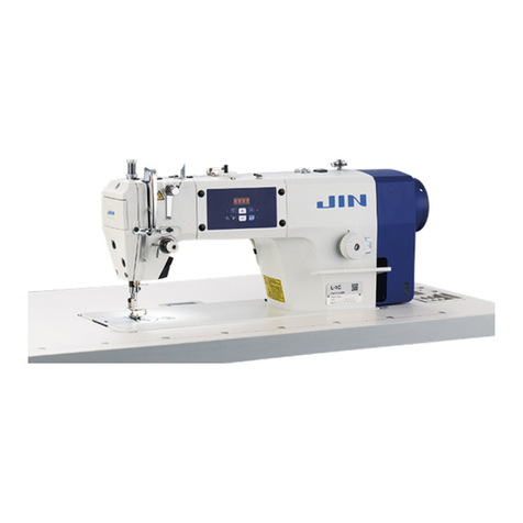
JUKI LZ-2290A-SS-7 Quick start guide

ENGINEER’S MANUAL
40011067
No.E355-01
Computer-controlled, Direct-drive, High-speed, 1-needle,
Lockstitch, Zigzag Stitching Machine
LZ-2290A Series
IP-100A / SC-915
IP-100D / SC-916
R

−1−
LZ-2290A-SU / -7
4,500 rpm (*1)
2.5mm/2.5mm (*3)
(Stepless fine adjustment)
1.4mm
LZ-2290A-SS / -7
5,000 rpm (*1)
5 mm/4 mm (*3)
(Stepless fine adjustment)
1.2 mm
LZ-2290A-DS / -7
5mm/4 mm (*3)
(Stepless fine adjustment)
1.2 mm
Light- to medium-weight materials
10 mm (*2)
8 kinds 14 patterns
(Custom pattern : 500 stitches, 20 kinds can be stored.)
SCHMETZ 438, ORGAN DPX5 : #65 to #90
178 mmX517 mm
4,000 rpm (Excluding a certain territory of export)
33.4 mm
Built-in in the upper face of machine head type (with bobbin thread retaining plate)
Electromagnetic front-wiping system (WB), electromagnetic side-wiping system (CB)
Built-in electromagnetic system
5.5 mm
10 mm
6 to 6.5 mm
Direct drive system (compact AC servo motor)
Timing belt system
Rated output 450W
3-phase 200 to 240V, Single phase 100 to 120V
DC34V
Presser foot micro-lifting screw is provided as standard.
1. AK-121 (Auto-lifter : Part No. : GAKA21000B0)
2. Exclusive grease tube for maintenance 10g (JUKI grease A Part No. : 40006323)
3. Exclusive grease can for maintenance 500g (Part No. : 23640204)
4. Touch-back kit asm. (Part No. ; 40010795) ... Other than WB, CB, OB, A-SR)
5. Optional switch kit (Part No. ; 40003640)
LZ-2290A-DU / -7
2.5mm/2.5 mm (*3)
(Stepless fine adjustment)
1.4mm
1. SPECIFICATIONS
* 1 : The sewing speed is regulated in accordance with zigzag width (A-SR : zigzag width and feed amount).
* 2 :Zigzag width is regulated to 8 mm at the time of delivery. (Max. zigzag width of all machines is 10 mm.)
* 3 : Normal and reverse feed amounts are regulated to 2 mm at the time of delivery.
Model
Application
Max. sewing speed
Max. zigzag width
Max. feed amount
(Normal/reverse)
Stitch pattern
Needle
Dimension of the bed
Number of revolution
of resistor pack
Needle bar stroke
Bobbin winder
Wiper
Automatic reverse
stitching device
Lubrication
Lift of the presser foot
(by hand lifter)
Lift of the presser foot
(by knee lifter)
Lift of the presser foot
(by AK auto-lifter)
Kind of the hook
(Part No.)
Bobbin case (asm.)
Heightof the feeddog (standard)
Lubricationof theface
plate section
Drive system
Transmissionfunction
Motor output
Operating power
Solenoid drive power
Additional function
Major optional
devices
1
2
3
4
5
6
7
8
9
10
11
12
13
14
15
16
17
18
19
20
21
22
23
24
25
26
27
Lubrication system to oil tank for hook
lubrication
JUKI New Defrix Oil No. 1 is used.
(Equivalent to ISO VG7)
Plunger pump is employed.
22525877
40003598 (with idle-prevention spring)
Minute quantity lubrication by oil wick
Full non-lubrication
23557259 (Non-lubrication hook)
Non-lubrication
4,000 rpm (*1)
LZ-2290A-SR-7
5,000rpm (*1)
5mm/5 mm
(0.1 adjustment by electronic control)
14 kinds 20 patterns
Stepping motor
control
Lubrication system to
oil tank for hook
lubrication
JUKI New Defrix Oil
No. 1 is used.
(Equivalent to ISO
VG7)
Plunger pump is
employed.
22525877
40003598
(with idle-
prevention spring)
1.2 mm
Minute quantity
lubrication by oil wick
(1) Specifications of the machine head
40003609 (with idle-prevention spring)

−2−
(2) Stitch pattern table
Name of pattern Stitch
pattern
Blind stitch (right)
Blind stitch (left)
Custom pattern
T stitch (left)
T stitch (right)
Pattern 1
Pattern 2 (fagoting)
Pattern 3
Pattern 4
Standard
scallop
Crescent
scallop
Equal-width
scallop
Equal-width
scallop
Standard
scallop
Crescent
scallop
Equal-width
scallop
Equal-width
scallop
Number of stitches
for pattern
Max.zigzag
width Remarks
1
2
4
6
24
12
24
12
2 + a
――
3
6
a
{
a
{
Straight stitch
Standard zigzag stitch
2-step zigzag stitch
3-step zigzag stitch
Scallop
(right)
Scallop
(left)
10
――
500

−8−
2) Adjusting the feed timing (for A-SR only)
Standard Adjustment
1
2
3
4
5
6
7
Mark on feed
adjustor
8
3
5
5
Engraved marker
dot on bed
Feed rocker
cam
Feed
rocker rod
Alignment of
timing marks
Top suface of
throat plate
Comes down.
A
B
Timing mark on
face plate G
I
Engraved marker line
on thread take-up
Timing mark on
face plate F

−9−
Adjustment Procedures Results of Improper Adjustment
A. Procedure by removing the gear box large lid (Standard
adjustment) (A-SR)
1) Remove the gear box large lid. (Refer to 4-(1).)
2) Adjust the engraved marker line on the thread take-up to timing
mark G on the face plate.
3) Align the timing mark on the feed adjustor with the engraved
marker dot on the machine bed.
<<Confirmation of the standard timing>>
4) Timing mark of the feed rocker cam aligns with that of the feed
rocker rod. ... Standard state
Standard assembling adjustment is described below.
5) When they do not align with each other, loosen two setscrews
8in the hook driving shaft sprocket, and it is necessary to
align the timing mark of the feed rocker cam with that of the
feed rocker rod.
6) Tilt the machine head, remove feed stepping motor connector
1, and remove feed lever spring 2from the spring bracket.
* When removing feed lever spring 2, perform the work using the
radio pincers or the like.
7) Loosen two setscrews 3in the feed stepping motor link C and
draw out feed link shaft 4to the right-hand side.
8) Remove three setscrews 5in the feed stepping motor unit.
9) When removing the feed stepping motor unit, remove oil pipe
7from oil pipe guide 6.
10) In the state of 3), loosen two setscrews 8in the hook driving
shaft sprocket, and adjust the timing mark on the feed rocker
cam to that on the feed rocker rod.
11) When re-assembling the feed stepping motor unit, refer to 3-
(3)-2) Adjusting the feed amount.
B. Procedure with the gear box large lid installed (For fine
adjustment) (A-SR)
It is possible to check standard timing without opening the gear
box large lid.
1) Adjust the engraved marker line on the thread take-up to timing
mark F on the face plate.
2) It is the standard timing that the top surface of feed dog almost
aligns with the top surface of throat plate when the feed dog
sinks. However, the height of feed dog is 1.2 mm at the time of
standard delivery.
3) Align the timing mark on the feed adjustor with the engraved
marker dot on the machine bed. (When feed amount is “0”)
4) When they do not align with each other, loosen two setscrews
8in the hook driving shaft sprocket and adjust the timing.
(For the adjustment procedure, refer to the aforementioned
items 1) through 6).
* Adjusting the feed timing (Common to A. and B.)
By performing the feed timing adjustment, stitch tightness
changes and sewing quality is improved according to the
process.
™When oil pipe guide6is forcibly
drawn, the oil pipe comes off or
damaged. As a result, oil
leakage will be caused.
™When changing the feed timing
other than the standard one, it
is easy to adjust when the
standard state is made a basis.
* When changing the feed timing
other than the standard one, and
sewing patterns that perform
normal/reverse feed motion (T
stitch, custom pattern, etc.),
needle may bend according to
the feed amount (needle snaps).
In this case, change the feed
timing from the panel and
compensate.
™Timing mark on the feed adjustor
is the inside mark. (Common to
A. and B.)
−12 −
2) Adjusting the feed amount (A-SR only)
Standard Adjustment
4
4
4
5
Normal feed amount : 0
Extreme left end
of speed variable
resistor
Straight stitching
12
3
1
3
2
Feed stepping motor unit
To smoothly rotate
6
Less
than
700g by
spring
balancer
is the
srandard.

−13 −
[Feed 0 adjustment]
For the adjustment of feed 0 position, perform fine adjustment of the
direction of rotation of feed adjustor 1.
1) Tilt the machine head and loosen two setscrews 2in the stepping
motor link C.
2) Adjust feed link shaft 3to the slippage amount of feed using a slotted
screwdriver and temporarily tighten two setscrews 2in the stepping
motor link C.
* Feed link shaft 3consists of eccenric pin.
3) Return the machine head to the home position, turn ON the power, set
the operation panel to straight stitching, and set normal feed amount
to “0”.
* Set the speed variable resistor of operation panel to the extreme left
end and set the sewing speed to 200 rpm.
4) Insert a sheet of paper under the presser foot and depress the pedal
to operate the sewing machine.
At this time, check the needle entry on the paper to check that feed
amount becomes “0”.
5) When feed amount is “0”, tilt the sewing machine head after turning
OFF the power and securely tighten two setscrews 2in the stepping
motor link C.
After securely tightening the setscrews, check that feed adjustor 1
smoothly moves with the presser foot lifted.
When the feed amount does not become “0”, turn OFF the power
again and repeat the work of steps 1) and 2).
[Feed 0 adjustment] : When feed amount does not become “0” by
adjusting feed link shaft 3only.
1) Loosen three fixing screws 4in the feed stepping motor unit and
perform the vertical adjustment of feed stepping motor unit 5.
2) After the adjustment, check that feed adjustor link 6smoothly moves
with the presser foot lifted.
3) The standard that feed adjustor link 6smoothly moves is the feed
mechanism torque (less than 700g by the spring balancer) before
setting the feed stepping motor unit. (Be sure to perform the centering
work so that the torque is less than 1,000g.)
[Normal/reverse feed amount control]
1) Input max. feed amount limitation value of normal/reverse feed with
the information of operation panel
* For the information operation, refer to Instruction Manual.
* Normal/reverse feed amount has been factory-set to the standard
adjustment value of JUKI standard delivery gauge (Part No. 40018430
... max. feed amount of normal/reverse stitching is 5 mm).
There are cases where the feed amount varies from the actual input
value in accordance with the material used or kind of gauge. Then
perform the input compensation.
Adjustment Procedures Results of Improper Adjustment
™Start the work of the feed amount
“0” adjustment after performing 3-
(2)-2) Adjusting the feed timing (A-
SR only).
™When there is a torque, one-sided
worn-out of feed link or step-out of
feed stepping motor 5will be
caused.
™When there is a torque, one-sided
worn-out of feed link or step-out of
feed stepping motor 5will be
caused.
Normal feed
small
Reverse feed
large
Normal feed
large
Reverse feed
small

−56 −
(3) Replacing the timing belt
*The timing belt !1 (22505705) of the highest quality is used, and it is not necessary to replace it
unless a special trouble occurs.
1) Perform removing/installing of the motor in
accordance with the steps of 4. - (2)
Replacing the motor.
<<A-SS(-7), A-SU(-7), A-DS-7, A-DU-7>>
2) Tilt the sewing machine, remove back-
magnet setscrews 9and remove back-
magnet !0.
3) Pressing timing belt !1 in the right-hand
direction, turn the timing belt to the front
by fingers, then the timing belt can be
removed.3) Pressing timing belt !1 in the
right-hand direction, turn timing belt !1 to
the front by fingers, then timing belt !1
can be removed.
4) Replace timing belt !1 with a new one and
install again by reversing the above order.
<<A-SR only>>
2) Tilt the sewing machine, remove feed stepping motor connector !2, and remove feed lever spring
!3 from the spring bracket.
* When removing feed lever spring !3, perform the work using a radio pincers or the like.
3) Loosen two setscrews !4 in the stepping motor link C and draw out feed link shaft !5 to the right-
hand side.
4) Remove three setscrews !6 in the feed stepping motor unit.
5) Similarly, perform the work as the aforementioned steps 3) and 4) of <<A-SS(7), A-SU(-7), A-DS-
7, A-DU-7>>.
Procedures of disassembling/assembling
9
!1
!0
Rubber
cushion
Plunger
!1
!2
!3
!4
!6
!4
!5
!6
!6

−57 −
68
™When removing/installing the motor, unless the motor is
defective, loosen coupling setscrew 8without loosening
coupling setscrews 6and remove the motor with the coupling
installed.
™When the motor is separated
from the coupling, set the
clearance between the end face
of the motor and that of the
coupling to 0.5 mm when re-
assembling.
™For re-assembling the stepping
motor unit, refer to 3-2)
Adjusting the feed timing.
0.5 mm
Caution in disassembling Caution in assembling

−70 −
(6) Adjusting/assembling the reverse feed control lever (A-SR only)
1
Procedures of disassembling/assembling
1) Loosen setscrews in the handwheel in the order
of screw No. 2 2and screw No. 1 1, and
remove the handwheel.
2) Remove four setscrews 4in the pulley cover
3, and remove pulley cover 3.
3) Temporarily assemble the handwheel again.
(Assembling the handwheel is due to the
workability.)
4) Turn the handwheel and adjust it to UP-stop
position (60 º).
5) Turn the power ON, press switch 5to display
the information screen.
2
3
4
Engraved
marker line on
the face plate
Engraved marker line on the
thread take-up
5

−71 −
Caution in disassembling Caution in assembling
™Be very careful of handling the magnet assembled to the
handwheel.
(Be careful of the damage or collection of dust or the like.)
™Align the engraved marker line on the thread take-up with that
on the face plate at UP-stop position.
™Set the handwheel to the position
where the clearance between
pulley cover 3and the
handwheel is approximately 1
mm, and adjust screw No. 1 1
to the flat position of the motor
shaft. Then tighten the screws
in the order of screw No. 1 1
and screw No. 2 2in the
direction of rotation of the
handwheel.
™Make the position of handwheel
flush with the end of the motor
shaft and adjust screw No. 1 1
in the direction of rotation of the
handwheel to the flat position of
of the motor shaft.

−72 −
6) Press switch 6to display the sewing common data screen.
7) Press switch 7from the first screen of sewing common data setting to display the second screen.
8) Press switch 8for approximately three seconds from the second screen of sewing common data
setting to change to the third screen.
9) Press switch 9from the third screen of sewing common data setting to change to the reverse feed
control lever adjustment screen.
6
Procedures of disassembling/assembling
7
8
Information screen (Operator level)
9
The first screen of sewing common data setting
The second screen of sewing common data setting
The third screen of sewing common data setting

−73 −
Caution in disassembling Caution in assembling

−74 −
10) When reverse feed control lever !0 is turned on in the reverse feed control lever adjustment screen,
the numeric value on the panel changes.
When the numeric value is not within the range of 22 to 32 (standard assembling value) with reverse
feed control lever !0 lifted (off), re-adjust as described in 11) and after.
Procedures of disassembling/assembling
Level meter changes.
!5
!6
Numeric value changes.
off
on
11) Adjusting the reverse feed control lever sensor
Loosen setscrew!2 in the variable resistor link.
Turn the feed lever sensor shaft and adjust
the numeric value of the reverse feed control
lever adjustment screen to 22 to 32 (standard
assembling value) using a flat-blade
screwdriver.
After the adjustment, tighten setscrew !2 in the
variable resistor link.
12) Replacing the reverse feed control lever
sensor
Loosen setscrew !2 in the variable resistor link
and remove variable resistor link !3.
Rmove two setscrews !5 in the feed lever
sensor installing plate and remove feed lever
sensor installing plate !6.
* Replace the sensor with a new feed lever sensor
(Part No. : HD001530000).
After the replacement, perform 11) Adjusting
the reverse feed control lever sensor.
(Caution) It is not possible to move to the other
screen from the reverse feed control
lever adjustment screen. When the
adjustment is completed, turn off
the power.
Reverse feed control lever adjustment screen
!2 !3

−75 −
Caution in disassembling Caution in assembling
!0
!0
off
on
™When the numeric value does not change or
E734 occurs, replace the feed lever sensor.
Refer to 12) Replacing the reverse feed control
lever sensor.
* E734 : Feed lever sensor error ... Feed lever
sensor detection trouble
Feed lever sensor : Part No. HD001530000
™Be sure to perform the check of the function of
the reverse feed control lever in the state that
reverse feed control lever return spring !1 is
hooked.
™When the power is turned off once in case of
replacing the feed lever sensor or the like, turn
the power on in the state that the flat position of
the feed lever sensor shaft is faced downward.
(E734 occurs.)
™Assembling position of variable resistor link !3
is the position where it lightly comes in contact
with the machined edge of feed lever link !4.
!1
!4
!3
Flat position of the feed
lever sensor shaft should
be faced downward.

−88 −
(9) Protruding amount of the hook shaft
1. Protruding amount of hook shaft 1from the end plane of hook shaft front metal 2is 9 mm.
(Caution) When the protruding amount is excessively large or small, lubrication failure will occur.
So, be careful.
1
2
9mm
(10) Adjusting the feed stepping motor unit (A-SR only)
Feed stepping motor link is treated as the selective part to improve the quality of the feed mechanism.
When replacing the part, be careful of the selection of selective parts.
1. For feed stepping motor connecting shaft 1,
there are four kinds which are different in outer
diameter tolerance of shaft, A to D. Select the shaft
which is of less looseness to the hole of feed
stepping motor link A asm. 2
2. There are grease grooves in the both ends of
bushing of feed stepping motor link A asm 2. and
a grease filling hole inside feed stepping motor
connecting shaft 1. Fill those parts with exclusive
grease (can type part No. 23640204 or tube type
part No. 40006323).
3. Connect feed stepping motor link B 3and feed
stepping motor link A asm. 2after making the
looseness in the shaft direction as small as
possible. Assemble feed stepping motor link A
asm. 2so that it can move by its weight.
4. Do not adjust the position of origin sensor
installing plate setscrew 4and feed stepping
motor link B 3.
1
2
3
4
Name of part
Feed stepping motor
connecting shaft A
Feed stepping motor
connecting shaft B
Feed stepping motor
connecting shaft C
Feed stepping motor
connecting shaft D
Remarks
There
are
engraved
marks at
the edge
sections.
Part No.
23544109
23544208
23544307
23544802
Outer diameter
tolerance
Maximum
Large
Medium
Small

−90 −
1Re-sewing switch
2Needle up/down
compensating switch
3Screen changeover
switch
4With/without reverse feed stitch
at sewing start switch
5With/without reverse feed stitch
at sewing end switch
6Reset switch
This switch is used to continue sewing from the step on the way
after replacing bobbin thread when bobbin thread has run out
during program stitching step.
This is the switch to perform needle up/down compensating
stitching. (Needle up/down compensating stitching and one stitch
compensating stitching can be changed over with function setting
No. 22.)
This is the switch to change over the screen.
This is the switch to turn ON/OFF automatic reverse feed stitch
at sewing start.
* This switch cannot be used with the sewing machine which is
not provided with automatic reverse feed stitching device.
This is the switch to turn ON/OFF automatic reverse feed stitch
at sewing end.
* This switch cannot be used with the sewing machine which is
not provided with automatic reverse feed stitching device.
This is the switch to make the value of bobbin thread counter or
sewing counter the set value.
1Re-sewing switch
2Needle up/down compensating switch
3Screen changeover switch
4
With/without reverse feed stitch at sewing start switch
5
With/without reverse feed stitch at sewing end switch
6 Reset switch
7Teaching switch
!5Power display lamp
!6 Smart media cover
!7 Smart media slot
(Smart media inserting opening)
!8 Smart media
(Optional :
Part No. HX005750000)
8Information switch
9Edge sensor switch
!0 One-shot stitching switch
!1
With/without automatic thread trimmer switch
!2Thread trimming prohibiting switch
!3Counter value setting switch
!4
Max.speed limitation variable resistor
6. OPERATION PANEL
(1) Names of the respective sections
14
!7
36
9
!0 !3
!5
!6
25 !4 !1 !2 8
7
!8

−91 −
7Teaching switch
8Information switch
9Feed amount display switch
!0
One-shot stitching switch
!1 With/without automatic
thread trimmer switch
!2 Thread trimming
prohibiting switch
!3 Counter value setting
switch
!4 Max. speed limitation variable
resistor
!5 Power display lamp
!6Smart media cover
!7 Smart media slot
(Smart media inserting opening)
This is the switch to set the setting of the number of stitches with
the value of number of stitches which has been actually sewn.
This is the switch to perform various function settings.
* LZ-2290A-SR only
Normal feed amount and reverse feed amount of the pattern
which is selected at present are displayed.
When this switch is set to effective at the time of program
stitching, the sewing machine automatically operates up to the
specified number of stitches.
When this switch is set to effective at the time of program
stitching, the sewing machine automatically performs thread
trimming when the specified number of stitches has been
completed.
This switch prohibits all thread trimmings.
* This switch cannot be used with the sewing machine which is
not provided with the automatic thread trimming device.
This is the switch to set the value of bobbin thread counter or No.
of pcs. counter.
When moving the resistor in the left direction, max. speed is
limited.
This lamp lights up when the power switch is turned ON.
This is the cover for smart media inserting opening.
To open the cover, place your finger on the notch located on the
side of the cover as shown in the figure and push the cover in the
direction of left slanting rear.
Do not close the cover unless smart media is completely inserted.
To set smart media, insert smart media into smart media slot and
push it until it is almost hidden.
To remove smart media, push it further again and it protrudes to
the position where it can be held between your fingers. Now, draw
it out.
* Be very careful of the inserting direction of smart media.
A: Reverse feed amount
B: Normal feed amount
*The above amounts are not displayed at
the time of cycle stitching.
A B

−92 −
(2) Information
Setting and checking of various data can be performed with the information.
For the information, there are the operator level and the maintenance personnel level.
[Operator level]
1. Turn ON the power. When the needle bar is not in the UP position, turn the handwheel to bring the
needle bar to its UP position.
2. Press switch 1to display the information screen.
3. Press switches 3, 5corresponding to the various functions.
[Maintenance personnel level]
1. Turn ON the power. When the needle bar is not in the UP position, turn the handwheel to bring the
needle bar to its UP position.
2. Press switch 1for approximately three seconds to display the information screen.
3. Press switches 2through 8corresponding to the various functions.
Information screen (Maintenance personnel level)
3:Sewing common data
5: Sewing management
information
2:Ver display
3:Sewing common data
4:Function setting
5:Sewing management
information
6:Communication mode
7:Hook adjusting mode
8: Smart media format
Information screen (Operator level)
1
1
35
23 4567 8

−93 −
1) Ver display
Software version of each CPU is displayed.
Press switch 2in the information screen (maintenance personnel level).
Ver display screen
Explanation of display
RV L
01- 01 01 00
Others
Level
Version
Revision
Kind of CPU
Panel software
Main software
Servo motor software
Excluding LZ-2290A-SR
LZ-2290A-SR only
Explanation of display
RV L
00- 00 00 00
Others
Level
Version
Revision
Kind of CPU
Panel software
Main software
Servo motor software
Feed motor software
This manual suits for next models
9
Table of contents
Other JUKI Sewing Machine manuals

JUKI
JUKI FLS-350N Series Quick start guide

JUKI
JUKI DSC-246 User manual

JUKI
JUKI DP-2100 Quick start guide

JUKI
JUKI MO-654DE User manual

JUKI
JUKI Q141 User manual

JUKI
JUKI LG-158 User manual

JUKI
JUKI MB-1373 User manual

JUKI
JUKI MF-7500 Series User manual

JUKI
JUKI LH-3500A series User manual

JUKI
JUKI DDL-8700L User manual

JUKI
JUKI MB-373N/BR10 User manual

JUKI
JUKI MB-1800B User manual

JUKI
JUKI CP-160 User manual

JUKI
JUKI LU-562 User manual

JUKI
JUKI HZL-80 series User manual

JUKI
JUKI PS-800SB-2850 Series User manual

JUKI
JUKI DDL-9000BHS User manual

JUKI
JUKI DLU-5490N User manual

JUKI
JUKI AC-172N-1790AN User manual

JUKI
JUKI MF-7523 User manual