JUKI MO-6000G Series Quick start guide

a.JUKI®
Super-High-Speed Ovel1ockMachine
High-Speed Ovel1ockMachine/SafetyStitch Machine
M0-6000S
series
M0-6900G
series
(forExtra-heavy-weightMaterials)
High-Speed VariableTop
Feed
OverlockMachine
M0-6900Rseries
M0-6900J
series
(forExtra-heavy-weight Materials)
ENGINEER'S MANUAL
·~:-·
·:~··:.:.:
,:·:
\
....
-~:~:
~,:·:·:·:·::·:·:·:·:;·~·:·:·:\·.:.·.·,::_::::
....
.
:.
·,:
.·
....
·.·.·.:.-.:
..
..
-~·
...
:\::
:
..
:.:
:~:
~::>:.::
::·.:::.:::L.-::.:
..
:,.·.::·,:
..
·
..
::>:.:.:;..:.:
..
:.>:::
·::::.:./::.:::::·::::
..
:~::::::·:~:.:~::::::·::::·::::~:g~,:::::::·:·:·::~:::\:::.·:::::)\;:y:
·:::
::·:·.
:·:·:.~~
29355807
No.E350-01
!
I
I
I
I·
I
11
I
l

ii
ll
11
!
PREFACE
This Engineer's Manual is written for the technical personnel who are responsible for the service and maintenance of
the machine.
The Instruction Manual for these machines intended for the maintenance personnel and operators at an apparel
factory contains operating instructions in detail. And this manual describes "Standard Adjustment", "Adjustment
Procedures", "Results
of
ImproperAdjustment", and otherimportantinformation which are notcovered bythe Instruction
Manual.
It is advisable to use the relevant Instruction Manual and Parts List described below together with this Engineer's
Manual when carrying out the maintenance ofthese machines.
In addition, for the motor for the sewing machine with thread trimmer, refer to the separate Instruction Manual
or
Engineer's Manual for the motor. And for the control panel, refer to the Instruction Manual for the control panel.
This manual gives the "Standard Adjustment" on the former page under which the most basic adjustment value
is
described, and
on
the latterpage "Results of ImproperAdjustment" under which stitching errors and troubles arising
from mechanical failures are described together with the
CIAdjustment
Procedures".
~
MO·6900S MO-6700S MO·6900G MO·6900R MO·6900J
Part No. Part No. Part No. Part No. Part No.
N
Instruction Manual 29351707 29351707 29351707 29356409 29363009
Parts List 29351806 29352408 29352309 29356201 29362803
From the Library of Superior Sewing Machine & Supply LLC

CONTENTS
1. SPECIFICATIONS ......._...•....•..•••.•.••••...•••..••••.••.••••••..•.••...••..•........•..•••.•..•••.••.•... 1
(1) MO-6700S SERIES ........................................................................................................... 1
(2) MO-6900S SERIES ...........................................................................................................2
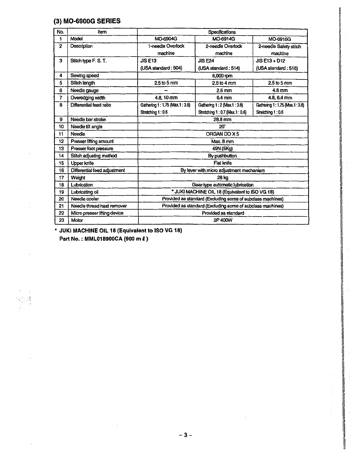
(3) MO-6900G SERIES
•••••••..•••••••..•••••••...••••••..••••..••••.•••••.•.•••.•....•.••...•••••...•.•••••.•.•.•.•••.•.•.•••.•.
3
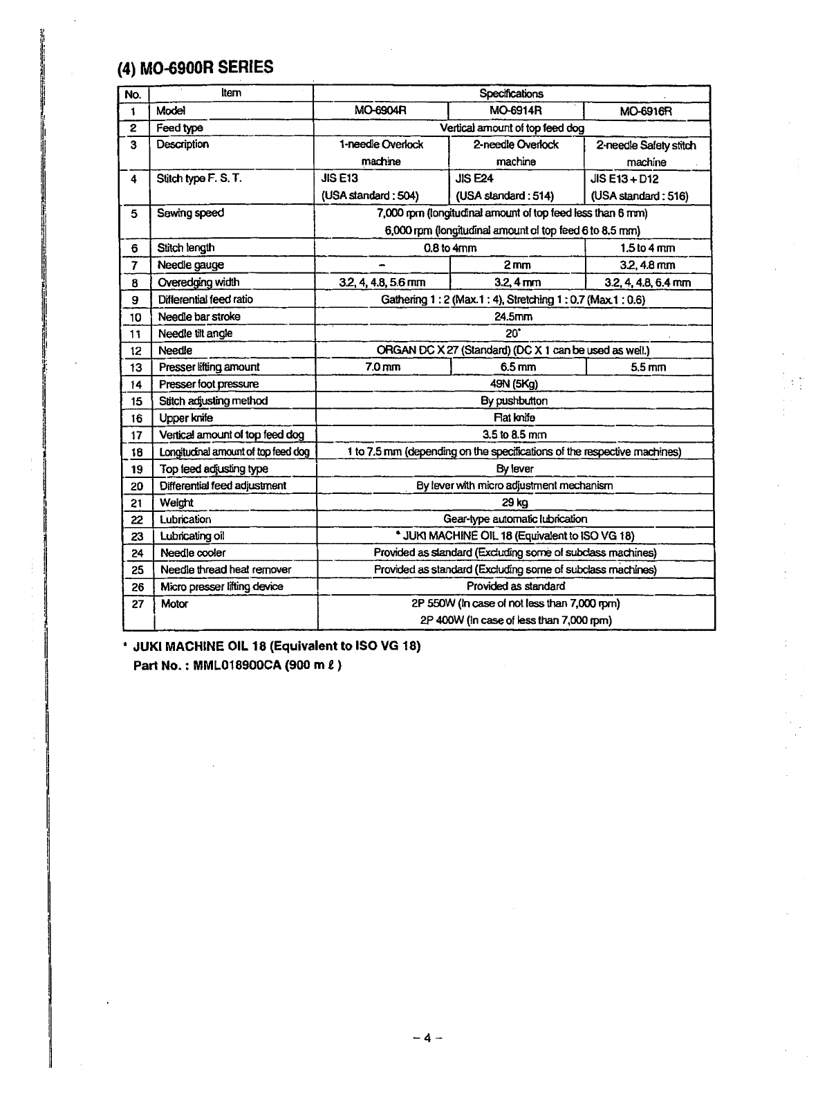
(4) MO-6900R SERIES •.••.•••••••••••.••••.•••.••••••••.•••••.......•.•..••..•••...•.......•.•.•••.•.••..•...•..••.....•.•.•...• 4
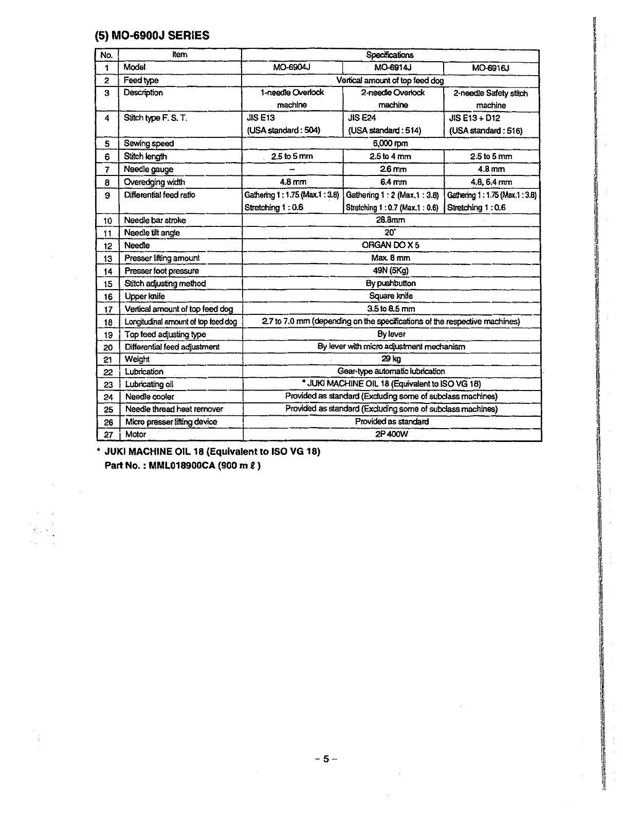
(5) MO-6900J SERIES.............................................................................................................5
2. MODEL NUMBERING SYSTEM ..••.••.•••..••••...••...•.•••••••.•••.•..•.••.•...•..•...••.•...•..... 6
3. STANDARD ADJUSTMENT ....••.•.•.•..•••..•.••••.••••••....•......•..•.•••.••......•.•.••.••.....•.. 8
(1)
Adjusting
the
needle
height
............................................................................................8
(2)
Positioning
the
throat
plate
............................................................................................ 8
(3)
Installing
position
of
the
needle Clamp .......................................................................
10
(4)
Adjusting
the
length
of
the
lower
looper
holder
(Applicable
only
to
MO-6.616S / MO-6916R, G, J
series)
...........................................
10
(5)
Adjusting
the
lower
looper
._
..........................................................................................
12
1)
Returning amount of the lowerlooper .................................................................................................... 12
2)
Clearance between the lowerlooperand the needle .............................................................................
12
(6)
Position
of
the
upper
looper
guide
...............................................................................
14
(7)
Positioning
the
upper
looper
holder
............................................................................
16
(8)
Positioning
the
upper
looper
........................................................................................
18
1) Height of the upper looper.................................................................................................
~
.................... 18
2) Longitudinal position
of
the upper looper................................................................................................ 18
(9)
Adjusting
the
double
chain
looper
· (Applicable
only
to
M0-6~
16S/MO-6916R, G, J series) ............................................... 20
1) Returning amount of the double chain looper.........................................................................................
20
2) Longitudinal motion {Avoid motion) ........................................................................................................
20
3) Clearance between the double chain looperand the needle ................................................................. 20
(10)
Adjusting
the
height
and
clearance
of
the
needle
guard
..............
~
.......................... 22
1) For 1-needle
or
2-needle overlock machine ...........................................................................................22
2) Forsafely stitch machine ........................................................................................................................ 22
(11)
Adjusting
the
height
of
the
feed
dog
.........................................................................
24
(12)
Adjusting
the
tillt
of
the
feed
dog
................................................................................
24
(13)
Adjusting
the
differential
feed
ratio
...........................................................................26
(14)
Longitudinal
position
of
the
feed
dog
.......................................................................
26
(15)
Adjusting
the
presser
foot
..........................................................................................28
1) Adjusting the tilt of the presser foot ........................................................................................................
28
2) Adjusting the micro-lifting mechanism of the presserfoot ......................................................................
28
(16)
Positioning
the
upper
knife
arm
shaft
.......................................................................
30
(17)
Positioning
the
upper
and
lower
knives,
and
available
overedge
widths
.............. 30
1)
lower
knife .............................................................................................................................................30
2) Upper knife .............................................................................................................................................30
3) Overdging width......................................................................................................................................30
(18)
Resharpening
of
the
knife
..........................................................................................32
(19)
Position
of
the
thread
cam
(Applicable
only
to
MO-6~16~
series)
........................
32
1) Adjustment of the thread cam.............................................:................................................................... 32
2) Adjusting looperthread cam thread guides A and B and the looper thread cam nail............................. 32
From the Library of Superior Sewing Machine & Supply LLC

rl!
~
11
1·
I
I
l~i
11
I
1
11
,,
~
I
I
!I
•l
!I
~
I
(20)
Adjusting
the throat plate support.............................................................................
34
(21)
Adjusting
the
feed mechanism
cover
presser.......................................................... 34
(22)
Adjusting
the
looper
cover
.........................................................................................
36
(23)
Adjusting
the
cloth
chip
cover
...................................................................................36
(24)
Adjusting
the needlemechanism............................................................................... 38
(25}
Position
of
the
upper
looper
lubrication
pin
.............................................................
40
1)
Orientation
of
the lubricating pin ............................................................................................................. 40
2)
Setting the lubricating pin ....................................................................................................................... 40
(26)
Longitudinal
momentum
of
the
top
feed
dog
(Top feed amount)...........................
42
(27) Vertical
momentum
of
the
top
feed
dog
.................................................................... 44
(28)
Adjusting
the
height
of
the
top
feed
dog
................................................................... 46
(29)
Locus
cut
of
the
top
feed
dog
....................................................................................48
(30)
Adjusting
the
longitudinal
position
of
the
top
feed
dog
.......................................... 48
(31)
Adjusting
the lateral
position
of
the
top
feed
dog
.................................................... 50
(32)
Position
of
the
motion
of
the
top
feed
dog
...............................................................
52
(33)
Adjusting
the feed
bar
guides
A and B.................................................................
~
.•..
54
(34)
Adjusting
the
top
feed
dog
pressure.........................................................................
56
(35)
Lifting
amount
of
the
top
feed
dog
(when operating
the
pedal)••....••..••..••.......•..••.•
56
(36)
Height
of
the presser (pedal operation)..................................................................... 58
(37}
Lifting
amount
of
the
top
feed dog (when
the
presser
lifting
lever
is
operated)
.••
60
(38) Position
of
the
thread
guides
and
the
looper
thread
take-ups................................ 62
(39)
Adjusting
soft
chain making mechanism.................................................................. 64
1)
Replacing· the parts with those exclusively designed
for
making soft chains ......................................... 64
2)
Adjustment value ....................................................................................................................................64 -
3} Important points
in
adjustment ............................................................................................................... 65
(40) Position
of
the
thread
guides
and
the
looper
thread take-ups
of
MO-6900G (J)... 66
4. ADDITIONAL INFORMATION AND PRECAUTIONS.....................................68
(1) Thread
tension
...............................................................................................................68
1)
Strength of tension spring.......................................................................................................................68
2)
Springs used
for
each model. .................................................................................................................68
(2) Upper looper·..................................................................................................................69
(3) Center-to-center distance
of
the
upper
looper
holder
............................................... 69
(4) Caution
in
assembly
......................................................................................................69
1) Application
of
sealant .............................................................................................................................
69
2) Precautions to
be
taken with respect to the lubricating components ...............................................
~
......
71
(5) Kinds
of
motor
pulleys,
belts
and frame
support
plate
bolts
.................................... 72
1)
Motorpulleys
and
belts........................................................................................................................... 72
2)
Pat
No.
of
frame support plate bolt .........................................................................................................73
(6)
Inspection
and replacement
of
the
cartridge
filter
..................................................... 73
5. ADJUSTMENT
OF
THE NEEDLE HEIGHT AND LOOPER TIMMING........... 74
(1) MO-60006. SERIES ........................................................................................................
74
6. TROUBLES AND CORRECTIVE MEASURES...............................................75
7. DIMENSIONS
OF
TABLE
••...••.••..••••....•.•..•.•.••••.•..•••.•..••••..••.••••••..•••.•••.••..••.•..
87
(1) Semi-sunken
type
..........................................................................................................
87
(2) Fully-suken
type
..................u
........................................................................................
88
From the Library of Superior Sewing Machine & Supply LLC

1
..
SPECIFICATIONS
(1) MO-6700S SERIES
No.
Item
1
Model
2
Description
3
Stitch
type
F.
S.
T.
4
Sewing
speed
5
Stitch
length
6
Needle
gauge
7
Overedging
width
8
Differential
feed
ratio
9
Needle
bar
stroke
10
Needle
tilt
angfe
11
Needle
12
Presser
lifting
amount
13
Presser
foot
pressure
14
Stitch
acfJUstlng
method
15
Upper
knife
16
Differential
feed
adjustment
17
Weight
18
Lubrication
19
Lubricating
oil
20
Needle
cooler
21
Needle
thread
heat
remover
22
Micro
presser
lifting
device
23
Motor
Specifications
M0-67048 M0-67148 . M0-6716$
1-neecile
Overlock
2-needle
Overlock
2-needle
Safety
stitch
machine
machine
machine
JISE13 JISE24 JISE13+D12
(USA
standard
:
504)
(USA
standard:
514)
(USA
standard
=
516)
7,000,pm
. 0.8to4mm
1.5to4mm
-
2,
2.4,
3.2
mm
2.
3.2,
4,
4.8
mm
1.6,
3.2,
4,
4.8
mm
32,4,4.Bmm
3.2,
4,
4.8,
6.4
mm
Gathering
1 =2
(Max.1
:
4),
Stretching
1:
0.7
(Max.1
:
0.6)
24.5mm
20·
ORGAN
DC
X
27
(Standard)
(DC
X 1
can
be
used
as
well.)
7.0mm
6.5nm
7.0mm
49N
(5Kg)
By
pushbutton
FlatknHe
By
lever
with
micro
adjustment
medlanism
28kg
Gear-type
automatic
lubrication
•
JUKI
MACHINE
OIL
18
(Equivalent
to
ISO
VG
18)
Optional
Optional
Provided
as
standard
2P
550W
(In
case
of
7,000
rpm)
2P
400W
(in
case
of
less
than
7,000
rpm)
* JUKI MACHINE
OIL
18 (Equivalent to ISO
VG
18)
Part No. : MML018900CA (900 mg)
-1
-
111
11
11
I'
·I
11
II
'I'
11
ij
L
I
r·
!I
·1
j
~
i
11i.
I:
li
111
Ii
1'
Ii
~
i
ii
'I
I
i
I
l
.I
I
I
From the Library of Superior Sewing Machine & Supply LLC

(2)
MO-6900S
SERIES
No.
Item
Specifications
1
Model
MD-69045
M0-6914$ MQ-69168
2
Description
1-needle
Over1ock
2-neeclle
Over1ock
2-needfe
Safety
stitch
machine
machine
machine
3
Stitch
type
F.
S.
T.
JIS
E13
JIS
E24
JISE13+
D12
(USA
standard
:
504)
(USA
standard:
514)
(USA
standard
:
516)
4
Sewing
speed
8,500rpm
8,000rpm
5
Stitch
length
0.8to4mm 1.5to4mm
6
Needle
gauge
-
2,
2.4,
3.2
mm
2,
3.2.
4,
4.8
mm
7
Overedging
width
1.6,
3.2,
4,
4.8
mm
3.2,
4, 4.8
mm
3.2,
4,
4.8,
6.4
mm
8
Differential
feed
ratio
Gathering
1:2
(Max.1
:
4),
Stretching
1:0.7
{Max.1
:
0.6)
9
Needle
bar
stroke
24.5mm
10
Needle
tilt
angle
20·
11
Needle
ORGAN
DC
X27
(Standard)
(DC
X1
can
be
used
as
weil.)
..
12
Presser
lifting
amount
7.0mm
6.5mm
7.0mm
13
Presser
foot
pressure
49N
(5Kg)
14
Stitch
adjusting
method
By
pushbutton
15
Upper
knife
Flat
knife
16
Differential
feed
adjustment
By
lever
with
micro
adjustment
mechanism
17
Weight
28kg
18
Lubrication
Gear-type
automatic
lubrication
19
Lubricatina
oil
"
JUKI
MACHINE
OIL
18
(Equivalent
to
ISO
VG
18)
20
Needle
cooler
Provided
as
standard
(Exduding
some
of
subclass
machines)
21
Needle
thread
heat
remover
Provided
as
standard
{Excluding
some
of
subdass
machines)
22
Micro
presser
lifting
device
Provided
as
standard
23
Motor
2P
550W
(In
case
of
not
less
than
7,000
rpm)
2P
400W
(In
case
of
less
than
7,000
rpm)
* JUKI MACHINE OIL
18
(Equivalent to ISO VG 18)
Part No. : MML018900CA (900 m ! )
-2-
From the Library of Superior Sewing Machine & Supply LLC

(3) MO-6900G SERIES
No.
·
Item
Specif
cations
1
Model
M0-6904G
M0-6914G M0-6916G
2
Description
1-needle
Overlock
2-needle
Overlock
2-needle
Safety
stitch
machine
machine
machine
3
Stitch
type
F.
S.
T.
JIS
E13
JISE24 JIS E13+ 012
(USA
standard
:
504)
(USA
standard
:
514)
(USA
standard:
516)
4
Sewing
speed
6,000rpm
5
Stitch
length
2.5to5mm 2.5to4mm 2.5to5mm
6
Needle
gauge
-
2.6mm
4.8mm
7
Overeclging
width
4.8,
10mm 6.4mm 4.8,6.4mm
8
Differential
feed
ratio
Gathering
1:
1.75
(Max.1
:
3.8)
Gathering
1:2
(Max.1
:
3.8)
Gathering
1:
1.75
{Max.1
:
3.8)
Stretchirg
1:
0.6
Stretching
1:
0.7
(Max.1
:
0.6)
Stretching
1:
0.6
9
Needle
bar
stroke
28.8mm
10
Needle
tilt
angle
20·
11
Needle
ORGAN
DO
XS
12
Presser
frfting
amount
Max.Bmm
13
Presser
foot
pressure
49N(5Kg)
14
Stitch
acfjUSting
methcxJ
By
pushbutton
15
Upperknife
Flat
knife
16
Differential
feed
adjustment
By
lever
with
micro
adjustment
mechanism
17
Weight
28kg
18
Lubrication
Gear-type
automatic
lubrication
19
Llbricating
oil
*
JUKI
MACHINE
OIL
18
(Equivalent
to
ISO
VG
18)
20
Needle
cooler
Provided
as
standard
(Excluding
some
of
subclass
machines)
21
Needle
thread
heal
remover
Provided
as
standard
(Excluding
some
of
subclass
machines}
22
Micro
presser
lifting
device
Provided
as
standard
23
Motor
2P400W
• JUKI MACHINE OIL 18 (Equivalent to ISO VG 18)
Part No. : MML018900CA (900 m 2)
-3-
·-
·-
t
I
l1
I~
~l
11
II
-!
II
I
I
From the Library of Superior Sewing Machine & Supply LLC

11
!11\·
I,
'I
l
fi
11
11
II
·I
i
11
!i
(4)
MO-6900R
SERIES
No.
Item
Specifications
1
Model
M0-6904R M0-6914R M0-6916R
2
Feed
type
Vertical
amount
of
top
feed
dog
3
Description
1-needle
Overlock
2-needle
Over1ock
2-needle
Safety
stitch
r:nachine
machine machine
4
Stitch
type
F.
S.
T.
JIS
E13
JIS
E24
JISE13+D12
(USA
standard :
504)
(USA
standard
:
514)
{USA
standard
:
516)
5
Sewing
speed
7,000
rpm
(longitudinal
amount
of
top
feed
less
than
6rrm)
6,000
rpm
(longitudinal
amount
of
top
feed
6
to
8.5
mm)
6
Stitch
length
0.8to4mm 1.5to4mm
7
Needle
gauge
-2mm 32,4.Bmm
8
Overedaina
width
3.2
1
4,
4.8,
5.6
mm
3.2.4nm
3.2,
4,
4.8,
6.4
mm
9
Differential
feed
ratio
Gathering
1:2
(Max.
1:
4),
Stretching
1:
0.7
(Max.1
:
0.6)
10
Needle
bar
stroke
24.5mm
11
Needle
tilt
angle
20·
12
Needle
ORGAN
DC
X
27
(Standard)
(DC
X 1
can
be
used
as
well.)
13
Presser
lifting
amount
7.0mm 6.5mm 5.5mm
14
Presser
foot
pressure
49N
(5Kg)
15
Stitch
adjusting
method
By
pushbutton
16
Upper
knife
Rat
knife
17
Vertica!
amount
of
top
feed
dog
3.5to8.5mm
18
Lonaitudnal
amount
of
top
feed
dog 1
to
7.5
mm
(deoending
on
the
~ifications
of
the
respective
machines)
19
Top
feed
adjusting
type
By
lever
20
Differential
feed
adjustment
By
lever
with
micro
adjustment
mechanism
21
Weight 29kg
22
Lubrication
Gear-~,pe
automatic
lubrication
23
Lubricating
oil
*
JUKJ
MACHINE
OIL
18
(Equivalent
to
ISO
VG
18)
24
Needle
cooler
Provided
as
standard
(Exduding
some
of
subclass
machines)
25
Needle
thread
heat
remover
Provided
as
standard
(Excluding
some
of
subclass
machines)
26
Micro
presser
lifting
device
Provided
as
standard
27
Motor
2P
55DW
(In
case
of
not
less
than
7,0CYJ
rpm)
2P
400W
(In
case
of
lessthan
7,000
rpm)
• JUKI MACHINE OIL
18
(Equivalent to ISO
VG
18)
Part No. : MML018900CA (900 m f )
-4-
From the Library of Superior Sewing Machine & Supply LLC

(5) MO-6900J SERIES
No.
Item
.
Specifications
1
Model
M0-6904J M0-6914J M0-6916J
2 Feedtype
Vertical
amount
of
top
feed
dog
3
Description
1-needle
Orerlock
2-needle
Overlock
2-needle
Safety
stitch
machine machine
machine
4
Stitch
type
F.
S.
T.
JIS
E13
JISE24
JIS
E13+ 012
(USA
standard:
504)
(USA
standard:
514)
(USA
standard
:
516}
5
Sewing
speed
6,000rpm
6
Stitch
length 2.5to5mm 2.5to4mm 2.5to5mm
7
Needle
gauge
-2.6mm 4.8mm
8
Overedging
width
4.8mm 6.4mm 4.8,6.4mm
9
Differential
feed
ratio
Gathering
1:
1.75
(Max.1
:
3.8)
Gathering
1:2
(Max.1
:
3.8)
Gathering
1:
1.75
(Max.1:
3.8)
Stretching
1:
0.6
Stretching
1:
0.7
(Max.1
:
0.6)
Stretching
1:
0.6
10
Needle
bar
stroke
28.8mm
11
Needle
tilt
angle
20·
12
Needle
ORGAN
DOX5
13
Presser
lifting
amount
Max.8mm
14
Presser
foot
pressure
49N
(5Kg)
15
Stitch
acfJUsting
method
By
pushbutton
16
Upper
knife
Square
knife
17
Vertical
amount
of
top
feed
doa
3.5to8.5mm
18
Longitudinal
amount
of
top
feed
dog
2.7
to
7.0
mm
(depending
on
the
specifications
of
the
respective
machines)
19
Top
feed
adjusting
type
By
lever
20
Differential
feed
adjustment
By
lever
with
micro
adjustment
mechanism
21
Weight
29kg
22
Lubrication
Gear-type
automatic
lubrication
23
Lubricating
oil
*
JUKI
MACHINE
OIL
18
(Equivalent
to
ISO
VG
18}
24
Needle
cooler
Provided
as
standard
(Exduding
some
of
subclass
machines)
25
Needle
thread
heat
remover
Provided
as
standard
(Excluding
some
of
subclass
machines)
26
Micro
presser
lifting
device
Provided
as
standard
27
Motor
2P400W
* JUKI MACHINE OIL
18
(Equivalent
to
ISO
VG
18)
Part No. : MML018900CA (900 m £)
-5-
I
I
I!
l,
I,
11
I
i
ii
11
11
.I
l
From the Library of Superior Sewing Machine & Supply LLC

~'.
!j
i
I
I
2.
MODEL
NUMBERING
SYSTEM
I MO-6000 SERIES MODEL NUMBERING SYSTEM
~I
11
1
1 2 3 4 5 6 7 8 9 10
11
12 1314 15 16 17 18 19 20
21
22
M06666DDD6666/D666-DO6
II
I 4
Machine
code
5.
6
Seam
code 8
Needle
gauge
code
ll
I 7 ·6700 series 0 1-needle
03
Splicing
~
I
11
·I
*
11
ri!
*
,I
i
9 6900 series
7
Basic
specification
code
s
Standard
G
Extra
heavy-weight
materials
A
Variable
top
feed
type
J
Variable
top
feed
type
for
B 2.0mm
C 2.4mm,
26
mm
(for
extra-
heavy-weight
materials)
D
32mm
E 4.0mm
F 4.8mm
04
1-needle
3-threa~
overtock
(504)
05
For
blind
hemmong
(505)
12
2-neeclle
4-thread
mock
safety
stitch
(512)
14
2-needle
4-thread
overtock
(514)
16 2-needle
S.thread
safety
stitch
(516)
43
3-needle
6-thread
safety
stitch
45
2-needle
double
chainstitch
I
extra
heavy-weight
materials
* 6900only 1 4.8mm+2.0
mm
11:
11
I 9
Overedging
width
code
A
1.6mm
D 3.2mm
E
4.0mm
1O
Feed
dogcode
4 2-row
5
1-row
6 3-row
11
Material
code
Classification
based
on
materials
to be used
1
Extra
light-weight
to
light- Forlight-weight materials
such
as
weight
materials
shirts
or
the
Uke
F 4.8mm 7 4-row 2 Light-weight
to
medium-
Knit
wear
only
-----
H 6.4mm 3
weight
materials
General
fabrics
M 10.0mm 4
Medium-weight
to
heavy-
Knit wear
only
such
as
sweater or
N 18.0mm
weight
materials
the
fike
-5 Medium·weight to heavy-weight
materials
such
as
denim
or
the
like
------
6 For
heavy-weight
materials
7 Heavy-weight to extra
Heavy-weight
materials
for
jeans,
car
heavy-weight
materials
mattress,
etc.
12
Application
code
Classification
based
on
type
of
operation
and
process
0
Standard
1
For
blind
stitching
2
Forgathering
4
Forattaching
tape
5
For
binding
6
For
binding
tape
D Splicing•
E Car mattress
F
Soft
chain
•
In
case
of
the
splicing,
13th
figure
is
(1).
-6-
From the Library of Superior Sewing Machine & Supply LLC

13
Special
machine
code
Special
classification
of
machine,
structure
and
specification
other
than
gauge
set
0
Standard
6
Feed
dog
provided
w~h
a
lip
7
Upper
looper
high
throw
type
F
For
swim
suits
H
Upper
looper
extra
high
throw
type
M
For
zipper
1
For
splicing
15
to
18
Device
and
attachment
code
G0'2/O141
Presser
fo(?Vtape
guide
for
attaching
tape
G39/Q141
Presser foot (for sharp curve)/tape guide for
attaching
tape
L121
Blind
hemming
ruler
S159
Swing
type
ruffler
(pedal-intertocking
type
for
safety
stitch}
S161
Swing
type ruffler
(Manual
lever type for safety
stitch)
S162
Swing
type
ruffler
(Manual
lever
type
for
over1ock)
N077
Four-fold
binder
20
Machine
headcode
A
Standard
machine
head
(Common
to
all
specifications)
21
Accessory
code
A
Fa
general
export
*
B ForJE
G
For
China
22
Machine
head
code
0
Fully-sunken
type
Semi-sunken
type
The
numberings
after-..!'
(hyphen)
of
19th
figure
will
be
used
on
and
after
Apnl
1,
2002.
They
are
not
described
on
the
catalogue
or
the
fike.
•
The
general
export
s~ificationisfor
Hong
Kong,
U.SA,
Japan and
Singapore.
.. 7 -
I
J
l
j
I
I
11
lj
I,
\
I
i
I
II
·1
~
j:
11
I
11
11
I
,j
!11
,,
ij
11
I
ll
I~
!
I
I
I
From the Library of Superior Sewing Machine & Supply LLC

i'
!
1·
I
I
j
I
I:
I'
I
I
I·
1;
ii
I
.I
I!
i
I
I
I
I
3.
STANDARD
ADJUSTMENT
Standard Adjustment
(1) Adjusting
the
needle height
When the needle(s) is in the highest position,
the needle height from the throat plate surface should be as shown below.
(Unit: mm)
6~046
Model 1-needle/
2-needle
:
right
··-
~
11
z,z
1
,inJ,a
2-needle
:left
MO-
6l!.04S(R)
-l!.66
·l!..60 10.5 -
30-
-Lib.6
SD
~
:I
SOM
n ::i.,
CD
g:
R
~
MO-
6604S
-D.D.D.
·66H
11.3 -
Cl)
:II,"
Cl)
66146
MO-
6/\05S
-606
-66.H 11.3 -
.,[!~zzma
66166
fl)
507
11
:0
9.4
::,
MO-
6.6.125
-D.D.D.
Cl)
SOF
3 Cl)
I»
e:
MO-
SD.12S
-CE4 -40H
11.3
9.9
n
a,
2:o
MO-
Sb
14S (R)
-8~6
-3c7
10.5 9.1
:,
<
CD
Cl>
::i. MO· 6614S (R)
-B66
-2
0H
11.3
9.9
0
0
':,t: 40H
MO-
6b
16S(R)-D.D.b
-.t.60
10.5 -
n
C2'Z2222Z]n
en
MO-
Sil
16S(R)-b.66
-l!..6H 11.3 -
3
e.
II>
a,
MO- 6Li16S(R)-A.6.L'l -60H
13
-
g.~
MO- 6943R -6.D.6 -b.l::,7 10.5 9.9
-·
en
i~
MO- 66.43S
-61::J.{:j,
·6.D.H 11.3 9.9
::r
. -
MO-
6/\45S
-D.b.l:l -360 9.8 -
:i5:
MO· 6903G
-ON6
-3D1 15.4 -
0 MO· 6904GCJl-OF6 -700 14.4 -
0,
CD
MO-
6905G ·OM6
-760
15.4 -
0
p
MO-
6914G(Jl-CH6
-700
14.1
12.6
<-
MO-
6916G(J)-F
.0.6
-700
14.1 -
The adjustment
of
needle height
for
the
2-needle
overlock machine should be made in reference tothe
left needle.
(2) Positioning the throat plate
The
needle entry point should be such that the distances listed below are provided between the
needle slotedge of
the
throat plate and the centerof needle.
Over1ock
side
A 1.3
Double·chainstitch side B 1.0
Note that
"A:=1.8"
and
"8=1.5"'
for
M0-6~
16S (R)
-n6.6-60H,
(Unit:
mm)
"A=1.6" and "8=1.3" for
M0-69~6G,
J
-8-
A
From the Library of Superior Sewing Machine & Supply LLC

Adjustment Procedures
1) Take off the uppercover, loosen setscrew 8.of needle driving
forked crank Oand move needle driving forked crank O up
or
down to adjust the needle height.
(Caution) Do not fully loosen the setscrew 8 of the needle
driving forked crank
0.
If the needle driving forked
crank
has
got
out
of
position
laterally when
its
setscrew was loosened, fully loosenthe
setscrew and
turn
pulley
to
allow the forked crank
to
tum
until
it
settles
by
itself. Then tightenthe setscrew
to
fix
the
forked crank
at
that
position.
1} Loosen setscrews 8 of throat plate base O and move throat
plate base 8 back and forth to adjust dimension A or
B.
-9-
Results of Improper Adiustment
o Any other needle height than
specified here will badly affect
the action of the lower looper.
the timing for.catching the upper
looperthread, etc.
o Improper lateral position
of
the
needle driving forked crank will
cause seizure, play,
or
other
troubles.
o Improperly positioned throat
plate
will
cause
needle
breakage,
contact
of
the
needles will the throat plate,
or
other troubles.
From the Library of Superior Sewing Machine & Supply LLC

,11
!I
:-1
;ii
II
I
1l
Ii
I
'I
!1
'I
11
~
'!i
I
Standard Adjustment
(3) Installing position of the needle clamp
Needle clamp connecting stud Oshould fit with the bottom end of needle bar8
or
spaced within oto
0.5mm.
Oto 0.5 mm
Butt the needle clamp with the
bottom
end
of
the
needle bar. 0
(4)
Adjusting
the
length
of
the
lower
looper
holder
(Applicable
only
to
M0-6~
16S
/ M0-6916R,
G,
J
series)
The center-to-centerdistance should be 26 mm.
At this time, the clearance between the end surface of the arm and the neck of the ball should be
3.5mm.
26mm
-10
-
From the Library of Superior Sewing Machine & Supply LLC

Adjustment Procedures
1) Loosen setscrewOand adjust, byslightly turning needle clamp
8.
the clearance provided between the right-hand side needle
and the lower looper (for 2-needle overlock machine) and the
clearance provided between the needle hole
in
the throat plate
and the needle (for safety stitch machine).
1) Loosen setscrew O ofthe lower looper holder from the rear of
the frame.
Since it is difficult to accurately measure the center-to-center
distance. perform adjustment to provide a 3.5 mm distance
between the end surfaceof the arm and the neck of the ball as
illustrated.
-11
-
Results of Improper Adjustment
o
If
the
clearance
provided
betw~en the needle and
the
looper is excessive, the needle
thread will
be
likelyto skip at the
time of tucking.
o
If
the
clearance
provided
between
the needle and
the
looperisinsufficient, the needle
will break or the looper blade
point will be damaged causing
thread breakage.
o Increasing the center-to-center
distance
will
give
a
smaller
stroke of the dublechain looper
or
lower looper, and decreasing
the
distance
will give
larger
stroke.
II
ll
·I'
I
I
I
I
·1
I
From the Library of Superior Sewing Machine & Supply LLC

Standard Adjustment
(5) Adjusting the
lower
looper
1) Returning amount
of
the lower looper
The distance between the blade point
of
the
lower
looper
and the
center
of the needle
should be as follows when the lower looperis
at the extreme left of its stroke.
.:.::
8
~
(D
>
C:
o:c
Cl>
u
-
"'
ie
Cl>
c;=
.:.::
8
ii
(D
> C
o·-
..92
'g
je
C
(\I
~
~
<D
.:
C
~~
QI
"'
-e
t8
,.
•
C,
Og
:E
a,
U)
2) Clearance between the lower looper and the needle
The clearance should be Oto 0.1 mm.
0to0.1
mm
J
-12 -
Model
OAS
MO- 6604S{R)
SD.OSS
·OA4
to
OE4
006
OF4
MO·
6604S{R)-
OF6
OH4
0D4
toOE4
MO-
6604S
•
OF6
B04 to BE4
MO- 6
'°'
14S(R) •
B06
to
BES
MO-
6614S(R)
-
806
to
BFS
BE7
MO-
66125
-CE4
MO-
6612S
·DF6
MO·
6616S(A)
-66.0.
BE4
MO- 6.t).16S(R)
-00/.\
F66
MO·
6616S(R)
·F66
MO- 6943R
-666
MO-
6643S
-6.6.6
MO-
6903G
-ON6
MO-
6904G(J)
·OF6
MO-
6905G
-OM6
MO- 6914G(J)
-CHS
MO-
6916G(J)
-F66
(Unit: mm)
Dimension8
-
156
·210 4.0
3t).~
3t).O
500 3.7
SOM
46H
. 3.8
50H
-3lH
3.8
20H
4uH
3.8
·40H 4.0
50F
507 2.2
360
500 3.7
46.H
. 3.8
56H
-60H 2.8
-6.67
3.8
-.ti.6.H 3.8
-301 1.4
-700 3.5
-760
1.3
..
-700 3.3
-700 3.5
From the Library of Superior Sewing Machine & Supply LLC

Adjustment Procedures Results of Improper Adjustment
1) Returning amount
of
the lower looper o Excessive return of the lower
CD
Loosen setscrew • of lower loopersupport arm 8
and
adjust
looper
tends
to
cause·stitch
lower looper8 to make adjustment of the returning amount. skipping when filament thread is
(Referential information) used.
1. Radius 8 of lowerlooper8 will
be
66.9
mm
when the lower o Insufficient return of the lower
looper is inserted into lower looper support arm O until it looper tends to cause needle
contacts with stopper pin O and then is fixed.
thread
stitch
skipping
when
2. The rocking angle
of
the lower looperwill
be
2s·.
spun thread is used.
(M0-66665,
R)
The rocking angle of the lower looper will
be
32·.
(M0-6966G,
J)
2) Clearance between the lower looper and
the
needle o Excessive clearance will often
MO-6700S Series
cause
needle
thread
stitch
CD
Loosen setscrew8 of lower loopersupport arm Oto the extent skipping.
that it is temporarily tightened. Now, make the adjustment by o Insufficient clearance will cause
moving lowerlooper support arm 8 back and forth.
needle
breakage
due
to
the
MO-6900S,
R,
G,
J Series. contact of the looper with
the
CD
Loosen setscrew 8 of lowerlooper support arm 8 tothe extent needle,
or
produce scratches on
thatit
is
temporarilytightened. Then finelyadjustthe longitudinal the blade point of the looper.
position of the looper using fine adjustment screw O.
leading
to
needle
thread
®Turn fine adjustment screw 8 clockwise to move lower looper breakage
or
other troubles.
G away from the needle.
Tum thescrew counterclockwise to move lowerlooper8 closer
to it.
-13-
From the Library of Superior Sewing Machine & Supply LLC

Standard Adjustment
(6) Position
of
the upper looper g~ide
Vertical position :
To
be
in
close contact with
the
frame
guide
surface.
Laternal position :
To
be
pressed
against
the
upper
looper
guide
support
gauge
8.
0
Frame
guide
surface
(Unit: mm)
Model Dimension
Ci)
Q)
OAS
15A
a-i
c::
£
MO·
S.604S(R)
-OA4
lo
OE4
-210
co
6.605S
006
3.6A
E
~
OF4
360
~-3
8
'C
MO-
66.04S(A)-OF6 -500
~
OH4
SOM
a,
004
to0E4
4AH
'g
@~
a,
M0-6.l!:.045 ·OF6
~
50H
BD4toBE4
-3.6.7
[f]
a,
MO·
6614
S(R)·sos
to
BEG
C !...;6
:c
0
t'G
MQ.
6614
S(R}-806
to BF6 20H
,~
E 04.llH
~
BE7
8
'C
a,
MO-
6612S
-CE4 -40H
~7
>
0
Q)
=o
a,
Q)
507
ffil
C
MO·
6.6.12S
·DF6
"'
0
SOF
-14-
a,
C
:E
0
co
E
..c:;
g
~
?:-
.S!
co
Cl)
""')
cj
0
0
CJ)
CD
6
::E
(Unit: mm)
&St
~7
5.8
Upper
looper 13131909 13132006
guide
support
gauge
11
~
11545100 12375606
(Unit:
mm)
Modef Dimension(B
MO-
6.6.16S{R)
-6.Ab.
360
E@
3
500
BE4
~y
46H
MO·
6/\16S(R)
-00.6.
-
SOH
F.6..6.
MO·
6A16S{R)
-F.6.6 -60H
r,s.s
[iliJ
MO.
6943R
-61.).A
-D.D.7
~
MO·
6.6.43S
.,6_1.),,6, -6D.H i
MO.
6903G
-ON6
-301
[iJ
MO-
6904G(J) -OF6 -700
~~~
MO• 6905G
-OM6
-1.6.0
ff:
MO· 6914G(J)
-CHS
-700
u~
MO- 6916G(J)
-f66
-700
u~
From the Library of Superior Sewing Machine & Supply LLC

Adjustment Procedures Results of Improper Adjustment
1)
Fit
upper looper guide support gauge 8 over gauge fixing pin o If the upper looper guide has
0 which has been driven in frame 8 and secure the gauge improperly positioned vertically,
with
an
O ring. it will
cause
oil
leakage
or
Then position the gauge taking the marker dot engraved on
it
disturbed path
of
the
upper
or the chamfering direction as reference.
looper
with
resultant
stitch
2)
When installin upper looper guide support 81 press
it
against skipping.
the gauge while keeping the upper looper guide support into o If the upper looper guide has
close contact with the frame guide surface, then tighten the been inaccurately positioned
screws. laterally.
it
will
cause stitch
(Caution) Refer to "4- (4) -1) -
(J)
Various sealants" for the skipping,
or
contact with the
various sealants. looper.
-15-
From the Library of Superior Sewing Machine & Supply LLC

Standard Adjustment
(7) Positioning the upper looper holder
The distance between the bottom surface of the frame and the upperend of the upper looper holder
pin 8 should be as shown below when the upperlooper holderO is at the highest point of its stroke.
(Unit:
mm)
Model
Dimension&
OAS
156
45.0
-~
MO-
SLl.04S(R)
-OA4
to
OE4
·210
1 6Ll.05S
006
3All.
--
8
OF4
3ll.O
462
'C
MO-
M04S(A)·
OF6
-500
CS)
{:;
OH4
SOM
~
m
004
toOE4
46H
482
J
MO-
6.!i.04S •
OF6
53mm
t
0
l
llt(tllfl(llltltl((l/1
Bottomsurface
of
frame
50H
CS)
B04
loBE4
47.3
~
MO·
6614S(R)·
·3ll.7
u
B06toBE6
~
BO~
to
BF
Li.
20H
48.4
~
MO·
6614S(R)·
•
.g
BE7 4.ll.H
a,
MO-
6.ll.125 -CE4
·40H
> 46.8
0
Cl>
=a
G)
507
Cl>
46.9
~
MO-
6ll.12S
-DFG
-
(\I
SOF
3l:.O
MO-
66.16S(R)-6/\l\
46.2
500
GI
BE4
C 4.ll.H 48.2
:c
MO- 6Ll.16S(R)-
006
u 5Ll.H
as
E
Fll.D.
.c
MO-
6616S{R)
·F
D.6
-60H
.B
4B.4
",ID
en
2:-
.S!
MO-
6943R
-D.bD.
·6.D.7
47.3
a,
(/)
. -
MO-
6643S
-D.66
-6.ti.H
48.4-
MO-
6903G
-ON6
-301
512
Cl>
-~
MO-
6904G(J)-OF6 -700 50.7
GI
Ill
-,_
• (!J
MO-
6905G
-OM6
·1/:J.O
51.7
0
0
en
C0
6
MO-
6914G(J)-CH6
-700
49.3
:E
,-.
MO-
6916G(J)·FD.6 -700
48.B
-16-
From the Library of Superior Sewing Machine & Supply LLC
This manual suits for next models
21
Table of contents
Other JUKI Sewing Machine manuals

JUKI
JUKI MO-654DE User manual

JUKI
JUKI LH-1152-5 User manual

JUKI
JUKI LZH-1290-4 User manual

JUKI
JUKI LK-1900S-SS User manual

JUKI
JUKI Jtron JTR-DLU5490/SHU Series User manual

JUKI
JUKI APW-896N/IP-420 User manual

JUKI
JUKI LBH-1790 Series Quick start guide

JUKI
JUKI LZ-271 User manual

JUKI
JUKI HZL-G Series User manual

JUKI
JUKI DLU-5490N User manual

JUKI
JUKI HZL-F series User manual

JUKI
JUKI TSC-441 User manual

JUKI
JUKI MO-613V User manual

JUKI
JUKI MF-7700D Series Quick start guide

JUKI
JUKI DU-141H-4 User manual

JUKI
JUKI LU-2828V-7 User manual

JUKI
JUKI LK-1903BN/BR35 User manual

JUKI
JUKI LK-1930 User manual

JUKI
JUKI MO-50e User manual

JUKI
JUKI HZL-27Z User manual