JUKI LU-2220N-7 User manual

ENGLISH
LU-2220N-7
INSTRUCTION MANUAL

i
CONTENTS
1. SPECIFICATIONS.................................................................................................................... 1
2. INSTALLATION........................................................................................................................ 1
3. ADJUSTING THE BELT TENSION.......................................................................................... 2
4. INSTALLING THE SYNCHRONIZER SUPPORT ROD........................................................... 3
5. ATTACHING THE BELT COVER............................................................................................. 3
6. INSTALLING THE KNEE SWITCH.......................................................................................... 4
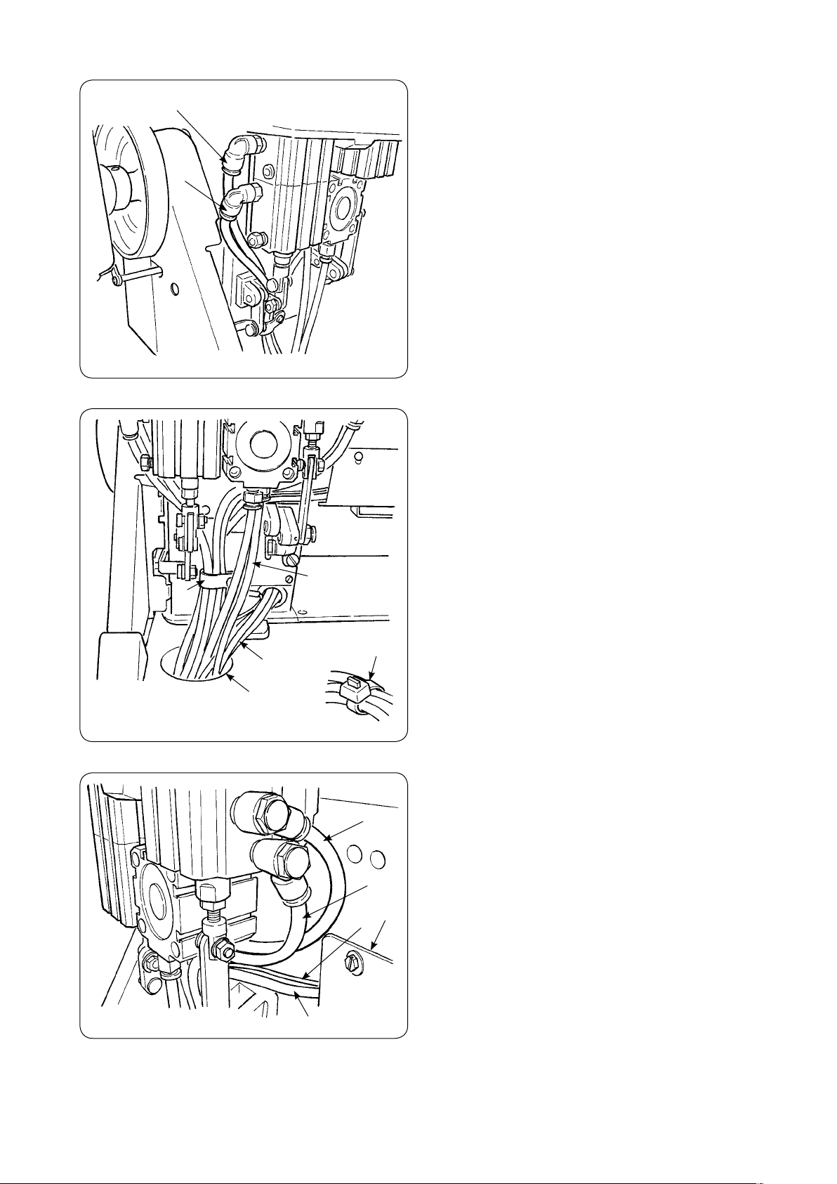
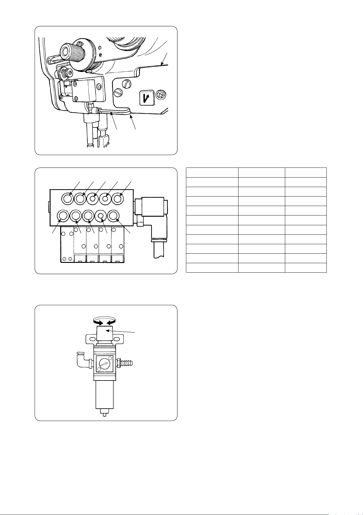
7. INSTALLING THE AIR DRIVE UNIT........................................................................................ 4
(1)Installing the air control unit ...............................................................................................................4
(2)Connecting the air hose....................................................................................................................... 5
(3)Adjusting the air pressure ................................................................................................................... 6
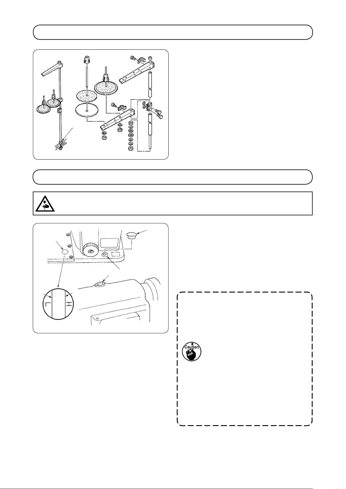
8. INSTALLING THE THREAD STAND....................................................................................... 7
9. LUBRICATION ......................................................................................................................... 7
10. ATTACHING THE NEEDLE ................................................................................................... 9
11. ATTACHING/REMOVING THE BOBBIN ............................................................................... 9
12. THREADING THE HOOK .................................................................................................... 10
13. INSTALLING THE THREAD GUIDE.................................................................................... 10
(1)Installing the needle thread guide rod.............................................................................................. 10
(2)Installing the bobbin winder thread guide ....................................................................................... 10
14. WINDING A BOBBIN ........................................................................................................... 11
15. ADJUSTING THE AMOUNT OF OIL IN THE HOOK .......................................................... 11
16. THREADING THE MACHINE HEAD................................................................................... 12
17. ADJUSTING THE STITCH LENGTH................................................................................... 13
18. THREAD TENSION............................................................................................................... 13
(1)Adjusting the length of thread remaining after thread trimming ...................................................13
(2)Adjusting the needle thread tension................................................................................................. 13
(3)Adjusting the bobbin thread tension ................................................................................................ 13
19. THREAD TAKE-UP SPRING ............................................................................................... 14
(1)When you want to change the stroke of the spring : ......................................................................14
(2)When you want to change the tension of the spring : ....................................................................14
20. HAND LIFTER / HANDHEBEL............................................................................................ 14
21. ADJUSTING THE PRESSURE OF THE PRESSER FOOT ................................................ 14
22. NEEDLE-TO-HOOK RELATION.......................................................................................... 15
23. ADJUSTING THE HOOK NEEDLE GUARD ....................................................................... 15
24. ADJUSTING THE BOBBIN CASE OPENING LEVER........................................................ 16

ii
25.
ADJUSTING THE THREAD TRIMMING MECHANISM COMPONENTS ................................16
(1) Positioning the thread trimming cylinder joint .............................................................................. 16
(2) Moving knife (Adjusting the vertical position)................................................................................ 17
(3) Counter knife (Adjusting the vertical position)............................................................................... 18
(4) Thread guide installing position....................................................................................................... 18
(5)-1. Counter knife
(Adjusting the travel amount) (Positioning of the counter knife base stopper)........... 19
(5)-2. Counter knife (Adjusting the lateral position)............................................................................. 20
(6) Adjusting the knife pressure ............................................................................................................ 21
(7)-1. Initial position of the moving knife drive arm and the moving knife ........................................ 22
(7)-2. Mounting position of the moving knife returning plate ............................................................. 23
(7)-3. Adjusting the clearance between the moving knife drive arm and the moving knife drive arm
stopper .............................................................................................................................................. 23
(8) Adjusting the thread trimming cam timing...................................................................................... 24
(9) Installing position of the clamp spring............................................................................................ 25
(10) Adjusting the condensation amount.............................................................................................. 26
(11) Explanation of the solenoid valve .................................................................................................. 27
26. ADJUSTING THE LIFTING AMOUNT OF THE PRESSER FOOT AND THE WALKING
FOOT................................................................................................................................... 28
27. SEWING SPEED TABLE ..................................................................................................... 28
(1) Max. sewing speed in accordance with the amount of the alternating vertical movement of the
walking foot and the presser foot................................................................................................... 28
28. RESETTING THE SAFETY CLUTCH.................................................................................. 28
29. OPERATION SWITCHES .................................................................................................... 29
30. KNEE SWITCH .................................................................................................................... 31
31. CAUTIONS WITH REGARD TO THE SEWING OPERATION ............................................ 31
32. TROUBLES IN SEWING AND CORRECTIVE MEASURES............................................... 32

− −
1. SPECIFICATIONS
Model LU-2220N-7
Applications Car seats, furniture, etc.
Sewing speed Max. 3,500 sti/min See “ 27. SEWING SPEED TABLE” on page 28.
Stitch length (max.) Normal feed : 9 mm Reverse feed : 9 mm
Needle SCHMETZ 34 x 35R (Nm 0 to Nm 60)
Hook Vertical-axis, .6-fold hook
Lift of presser foot Hand lifter lever : 9 mm Knee lifter : 6 mm
Lubricating oil JUKI New Defrix Oil No.
Noise
- Equivalent continuous emission sound pressure level (LpA) at the workstation :
A-weighted value of 85.5 dB; (Includes KpA = 2.5 dB); according to ISO 082- C.6.2
-ISO 204 GR2 at 3,500 sti/min.
- Sound power level (LWA) ;
A-weighted value of 9.0 dB; (Includes KWA = 2.5 dB); according to ISO 082- C.6.2
-ISO 3744 GR2 at 3,500 sti/min.
2. INSTALLATION
Spacer rubber
) When carrying the sewing machine, be sure to
carry by two people.
2) Do not place a protruding object, such as a screw
driver, at a place where the sewing machine is to
be installed.
3) Fix the hinge seats and the support rubbers sup-
plied with the machine on the table using nails.
When driving nail A, drive it slantingly
so that it does not pass through the
side of the small articles case.
Nail
Hinge seat
Rubber cushion
Support rubber of
the machine head
Small articles
case
Support rubber of the machine head
Nail
Nail
A
Nail
A
Small articles
case
Top surface of
the machine table
Support rubber of the
machine head

− 2 −
Oil pan
8
5
6
6
9
3
2
4
7
5) Attach drain plug 2, oil seal 3 and washer 4 to
the oil pan. Attach packing 6 and washer 9 to
screw 5 and x them with nut 7.
6) After they are xed, screw in waste oil container
8 into drain plug 2.
7) Insert hinge !0 into the bed hole, engage the
hinge with the rubber hinge of the table, and put
down the machine head onto the head support
rubber at four corners.
8) Install head support bar !1 rmly on the table by
inserting it into the table hole until it will go any
further.
3. ADJUSTING THE BELT TENSION
Adjust the belt tension with the height of the motor so
that the belt sags 5 mm when the center of V belt is
applied with a 9.8N load.
WARNING :
Turn OFF the power before starting the work so as to prevent accidents caused by abrupt start of
the sewing machine.
Handwheel
Motor pulley
9.8N
15mm
4) Fix oil pan 1 supplied with the machine on the
table in 8 places with wood screws.
Table
Align
1
50 mm
20 mm
Operator’s side Align
!1
!0 !0

− 3 −
) Fix belt cover (rear) 1 on the arm with screws 2.
2) Fit belt cover (front) 3 to notch (upper) A and
notch (lower) B of the belt cover (rear).
3) Fix belt cover (front) 3 with screws 4 and 5.
4) Fix belt cover auxiliary plate 6 at the position of
0 mm from the rear end with wood screws 7
when there is a clearance of 2.5 mm between the
belt cover and the auxiliary plate.
5) When tilting the machine head, loosen wood
screws 7 and move the belt cover auxiliary plate
in the direction of the arrow until it stops. Then, tilt
the machine head.
After attaching the belt cover, conrm
whether or not the respective cords do
not come in contact with the belt and
the handwheel. Disconnection of the
cords will result when they come in
contact with one another.
5. ATTACHING THE BELT COVER
4
A
4
1
3
5
B2
Notch (upper)
Notch (lower)
10 mm
2.5 mm
7
6
1
2
4. INSTALLING THE SYNCHRONIZER SUPPORT ROD
) Attach synchronizer support rod 1 to the arm
using attaching nut 2.
WARNING :
Turn OFF the power before starting the work so as to prevent accidents caused by abrupt start of
the sewing machine.
WARNING :
Turn OFF the power before starting the work so as to prevent accidents caused by abrupt start of
the sewing machine.

− −
(1) Installing the air control unit
1) Install regulator (asm.) 1 on the bottom surface
of the table with wood screw 2 supplied as
accessories.
2) Install air control unit (asm.) 3 on the bottom
surface of the table in four places with wood
screws 4 supplied as accessories.
4
2
3
1
7. INSTALLING THE AIR DRIVE UNIT
WARNING :
Turn OFF the power before starting the work so as to prevent accidents caused by abrupt start of
the sewing machine.
3) Install regulator (asm.) 1 and air control unit
(asm.) 3 in the broken line frame as shown in
the illustration on the left side. Determine the
installing position where it is convenient to the
user.
Rear view of table
6. INSTALLING THE KNEE SWITCH
1) Attach supporting base 2 of knee switch 1 onto
the underside of the table using wooden screws
3.
2) Fix cord 4 to an appropriate position on the table
using a staple supplied with the machine so as to
prevent the cord from hindering the operation.
4
2
3
1

− 5 −
2) Pass air hoses 3, 4 and 9 coming from the
sewing machine through hole !0 bin the table,
and connect them to the air control unit.
(There are clip bands in the accessories. Use
them to arrange the air hoses if necessary.)
(2) Connecting the air hose
) Connect the air hoses coming from the air control
unit to the air cylinders of the sewing machine
as shown in the illustration. Adjust the seal Nos.
pasted on the hoses to those pasted on the joints,
and connect as described in the list.
Be sure to pass the hoses through hole !0 in the
table.
After connecting them, bundle air hoses 1, 2, 5,
B, and C, 6-stage switch cord 6 using cable clip
!1 of the machine head.
Directly pass air hoses 7 and 8 through hole !0
in the table.
1
2
349
78
!0
!1
Clip band
C
B
6
5!2

− 6 −
(3) Adjusting the air pressure
Adjust the air pressure to 0.4 to 0.5 MPa using air
pressure regulating knob 1 of regulator. Pull knob
1 up and turn it to properly adjust the operating
air pressure. After the adjustment, press the knob
down into the home position.
1
Decrease Increase
B
C
57 3 1
Solenoid valve Cylinder
Condensation 1 1
BT 2 2
Thread trimming 3 3
Thread trimming 4 4
Thread clamp 5 5
FL 7 7
FL 8 8
DL 9 9
2P B B
2P C C
8 9 4 2
3) Pass air hoses 5 through cord cover !2 the same
as 6-range switch cord 6, pass them through
clearance A between 6-range switch !3 and the
machine arm, and connect them to the joint of air
hoses 5.
5
!3
A

− 7 −
9. LUBRICATION
5
2
43
1
LU-2220N-7
Oil window
) Pour the JUKI New Defrix Oil No. into the oil
tank in the bed from lubrication hole 1 until H
level 3 of oil gauge 2 is reached.
2) Add the same lubricating oil as soon as the oil
level has come down to L level 4.
3) After the lubrication, operate the sewing machine
and check that the oil rises up to the oil sight
window.
1. Do not use any lubrication oil other
than the specied type. Be sure to
close cap 5of the oil hole.
2. When you operate your machine
for the rst time after the set-up or
after an extended period of disuse,
apply two or three drops of oil to
the sections indicated with arrows.
(Refer to Fig. 1 on the next page.)
3. When you start the use of the
sewing machine which has not
been used for an extended period
of time, be sure to break in the
sewing machine at 1,800 sti/min for
approximately 10 minutes.
¡ In the case where the machine is operated with
the hook lled with normal amount of oil, the
oil level descends from H level to the L level in
approximately 00 hours .
WARNING :
Turn OFF the power before starting the work so as to prevent accidents caused by abrupt start of
the sewing machine.
) Assemble the thread stand and set it to the hole
of the table.
2) Tighten locknut 1 to x the thread stand.
8. INSTALLING THE THREAD STAND
1

− 8 −
Supply oil
Supply oil Supply oil
Flg.1
Filter
7
7
6
8
6
[Cleaning the lter]
) Approximately once a month, remove screws 6
from the lter case and clean magnet 7 and lter
element 8 inside the lter.
2) If the lter is clogged with soil, circulation failure
will result.
This will give rise to oil leakage from the upper
portion of the hook driving shaft saddle.

− 9 −
11. ATTACHING/REMOVING THE BOBBIN
1
) Lift latch 1 of hook, and take out the bobbin.
2) Put the bobbin into the shaft in the hook correctly
and release the latch.
10. ATTACHING THE NEEDLE
2
1
Use a SCHMETZ 34 x 35R needle.
) Turn the handwheel to bring the needle bar to the
highest position of its stroke.
2) Loosen needle clamp screw 2, and hold needle
1 so that the long groove in the needle is facing
exactly to the left.
3) Push the needle 1 deep into the needle clamp
hole until it will go no further.
4) Tighten needle clamp screw 2 rmly.
Long groove
WARNING :
Turn OFF the power before starting the work so as to prevent accidents caused by abrupt start of
the sewing machine.
WARNING :
Turn OFF the power before starting the work so as to prevent accidents caused by abrupt start of
the sewing machine.

− 0 −
2
1
13. INSTALLING THE THREAD GUIDE
(1) Installing the needle thread guide rod
) Install needle thread guide rod 1 with nut 2.
(2) Installing the bobbin winder thread
guide
) Attach bobbin winder thread guide 1 to the
bobbin winder on the machine arm using screws
2.
2) Adjust the position of the thread guide referring to
“14. WINDING A BOBBIN”.
1
2
12. THREADING THE HOOK
1
2
) Pass the thread through thread path 1 in the
hook and thread hole 2 in the lever, and draw the
thread.
Now, the thread will be brought to the thread hole
2 via the tension spring.
• Make sure that the bobbin revolves in the
direction of the arrow when you draw the thread.
WARNING :
Turn OFF the power before starting the work so as to prevent accidents caused by abrupt start of
the sewing machine.

− −
15. ADJUSTING THE AMOUNT OF OIL IN THE HOOK
) Adjust the amount of oil in the hook by turning
oil amount adjustment screw 1 mounted on the
hook.
2) Turning the adjustment screw clockwise will
decrease the amount of oil in the hook or
counterclockwise will increase it.
3) Place a piece of paper near the periphery of the
hook, and run the machine for approximately ve
seconds. The proper amount of oil in the hook is
obtained when the oil spots lightly make stripes
on the paper as shown in the gure.
A piece of paper
14. WINDING A BOBBIN
) Pass the thread in the order, A through H. Then
wind it several turns round the bobbin.
2) Tilt bobbin presser 1.
3) Adjust bobbin thread amount adjustment screw 2
to wind a bobbin about 90% of its capacity.
Turn the screw counterclockwise to increase the
amount of thread to be wound round the bobbin,
or clockwise to decrease it.
4) If the bobbin is wound unevenly, correct it by
moving thread guide 3 of the bobbin winder back
or forth.
Then tighten screws 4.
5) When the bobbin is lled up, the bobbin presser
automatically releases the bobbin and the bobbin
winder stops running.
AB
C
D
E
F
4
G
H
3
5
2
1
1
WARNING :
Turn OFF the power before starting the work so as to prevent accidents caused by abrupt start of
the sewing machine.
WARNING :
Turn OFF the power before starting the work so as to prevent accidents caused by abrupt start of
the sewing machine.

− 12 −
16. THREADING THE MACHINE HEAD
Thread the machine head following the order of A
through to P as shown in the illustration given above.
WARNING :
Turn OFF the power before starting the work so as to prevent accidents caused by abrupt start of
the sewing machine.
I
L
K
J
M
N
O
A
F
D
B
C
E
G
H
P
Threading method :
draw the thread to the operator's side.
Needle thread
N

− 3 −
Turn standard feed adjusting dial 1 or 2P feed ad-
justing dial 3 counterclockwise or clockwise so that
the number corresponding to the desired number is
brought to the top of the dial until the marking spot is
reached.
When turning 2P feed adjusting dial 3,
be sure to conrm that 2P switch is OFF.
The scale 3 or less of 2P feed adjust-
ing dial (place where the dial stops
with the dial stopper) is for adjusting
the 2P feed adjusting dial to "0" point.
The scale 3 or less cannot be used.
For the details of 2P device, refer to
"29. OPERATION SWITCHES".
[Reverse feed stitching]
) Press down reverse feed control lever 2.
2) Reverse feed stitching can be performed as long
as you keep pressing the lever down.
3) Release the lever, and the machine will run in the
normal feed direction.
17. ADJUSTING THE STITCH LENGTH
3
1
2
18. THREAD TENSION
(1) Adjusting the length of thread remaining
after thread trimming
Turn thread tension nut No. 1 clockwise A
to shorten the length of thread remaining after
thread trimming. Turn the nut counterclockwise B
to lengthen it.
(2) Adjusting the needle thread tension
Turn thread tension nut No. 2 2 clockwise
A to increase the needle thread tension, or
counterclockwise B to decrease it.
2
1
BA
BA
3
C
D
WARNING :
Turn OFF the power before starting the work so as to prevent accidents caused by abrupt start of
the sewing machine.
(3) Adjusting the bobbin thread tension
Turn tension adjustment screw 3 clockwise
C to increase the bobbin thread tension, or
counterclockwise D to decrease it.

− 4 −
19. THREAD TAKE-UP SPRING
IncreaseDecrease
2
5
14
3
20. HAND LIFTER / HANDHEBEL
1
(1) When you want to change the stroke of
the spring :
) Loosen screw 2 in the stopper, and move
stopper 3 to the right or left to change stroke of
thread take-up spring 1.
2) Move the stopper to the right to increase the
stroke of the thread take-up spring, or the left to
decrease it.
(2) When you want to change the tension of
the spring :
) Loosen nut 4, and move spring stud 5
counterclockwise to increase the tension of the
spring, or clockwise to decrease it.
) When you want to keep the presser foot in the
lifted position, turn hand lifter 1 in the direction of
the arrow. This makes the presser foot rise 9 mm
and stay at that position.
2) To make the presser foot come down to its home
position, lower the hand lifter.
1
Increase
Decrease
21. ADJUSTING THE PRESSURE OF THE PRESSER FOOT
) Turn presser spring regulating dial 1 clockwise
to increase the pressure of the presser foot, or
counterclockwise to decrease it.
(Be sure to operate the sewing machine with the
pressure of the presser foot minimized as long as
the presser foot securely holds the material.)
WARNING :
Turn OFF the power before starting the work so as to prevent accidents caused by abrupt start of
the sewing machine.

− 5 −
22. NEEDLE-TO-HOOK RELATION
0.02 - 0.1 mm 3
2
5
1
4
1.4 mm
2.0 mm
) Adjust the standard feed adjusting dial to "0".
2) Loosen hook driving shaft set collar clamping screw 3, and turn the handwheel counterclockwise to make
the needle bar ascend by 2.0 mm from the lowest position of its stroke.
3) In the state described in 2), align blade point 1 of the hook with the center of needle 2, and tighten hook
driving shaft set collar clamping screw 3. At this time, a clearance of .4 mm is provided between the blade
point of the hook and the top end of the needle eyelet. (As reference, the handwheel pointer meets the
marker line of the scale L on the handwheel.)
4) Loosen screw 4 in the top face of the bed and screw 5 in the hook driving shaft saddle, and adjust so
that a clearance of 0.02 to 0. mm is provided between the blade point of hook and the needle by moving
the hook driving shaft saddle to the right or left. Once the specied clearance is obtained, securely tighten
screws 4 and 5.
5) Set the standard feed adjusting dial to maximum value, and check that the blade point of the hook does not
come in contact with the needle.
The operation panel could come in contact with the thread stand when tilting the machine
head. To protect the relevant parts from contact, shift the thread stand to a position at which
the thread stand does not interfere with the control panel.
23. ADJUSTING THE HOOK NEEDLE GUARD
0.15 - 0.2 mm
1
2
When a hook has been replaced, be sure to check
the position of the hook needle guard.
As the standard position of the hook needle guard,
hook needle guard 2 must push the side face of
needle 1 to lean the needle by 0.5 to 0.2 mm away
from its straight position. If not, adjust the hook
needle guard by bending it.
) If you want to move the hook needle guard
inwards, turn adjusting screw 3 clockwise.
2) If you want to move the hook needle
guard outwards, turn adjusting screw 3
counterclockwise.
WARNING :
Turn OFF the power before starting the work so as to prevent accidents caused by abrupt start of
the sewing machine.
WARNING :
Turn OFF the power before starting the work so as to prevent accidents caused by abrupt start of
the sewing machine.
3
2
blade point

− 6 −
24. ADJUSTING THE BOBBIN CASE OPENING LEVER
) Turn the handwheel to move bobbin case opening
lever 1 in the direction of the arrow A, and
loosen screw 2.
2) Turn the handwheel to move bobbin case opening
lever 1 in the direction of arrow B, and loosen
screw 3.
3) Turn bobbin case 4 in the direction of arrow C
to until bobbin case stopper 5 rests in groove D
on throat plate 6. In this state, adjust so that a
clearance of 0. to 0.3 mm is provided between
top end E of bobbin case opening lever and
protrusion F on the bobbin case when they
approach most. Then, tighten screws 2 and 3.
F
6C
5
A
B
D
3
E4
0.1 - 0.3 mm
1E
2
(1) Positioning the thread trimming cylinder joint
Assemble thread trimming cylinder 1 and thread
trimming cylinder joint 2 as illustrated in the sketch at
left and secure with nut 3.
25.
ADJUSTING THE THREAD TRIMMING MECHANISM COMPONENTS
WARNING :
Turn OFF the power before starting the work so as to prevent accidents caused by abrupt start of
the sewing machine.
WARNING :
Turn OFF the power before starting the work so as to prevent accidents caused by abrupt start of
the sewing machine.
3
2
7.0 ± 0.5 mm
1

− 7 −
(2) Moving knife (Adjusting the vertical position)
) Loosen moving knife drive arm clamping screw
1 and moving knife shaft thrust collar setscrew
2 and tighten them again after adjusting the
vertical direction of moving knife 3. When
tightening moving knife drive arm clamping screw
1, perform the items (6), (7), (8) and (9) that are
mentioned later.
3
0.5 to 0.6 mm
Throat plate
Gauge for adjustment supplied as accessories
37.8 mm
26.8 mm
29 mm
Thickness : 0.6 mm
43 mm
2) The vertical position of moving knife is the
position where the clearance between the bottom
surface of throat plate (reverse side) and the top
surface of moving knife 3 is 0.5 to 0.6 mm.
(At the time of adjustment, the gauge for
adjustment supplied as accessories can be used.)
2
1
Table of contents
Other JUKI Sewing Machine manuals

JUKI
JUKI AMS-210EN Series User manual

JUKI
JUKI LU-2810 Series User manual

JUKI
JUKI MS-1261/V045 User manual

JUKI
JUKI LK-1850 Series User manual

JUKI
JUKI MO-104N User manual

JUKI
JUKI LU-2810 Series Quick start guide

JUKI
JUKI HZL-F400 User manual

JUKI
JUKI J-350QVP User manual

JUKI
JUKI MS-1190 User manual

JUKI
JUKI MO-644 User manual

JUKI
JUKI Exceed F-600 User manual

JUKI
JUKI LZ-2290A-SS-7 Quick start guide

JUKI
JUKI PLK-J4040R3 User manual

JUKI
JUKI HZL-F series User manual

JUKI
JUKI HZL-E80 User manual

JUKI
JUKI MF-7900 Series User manual

JUKI
JUKI TL-98E User manual

JUKI
JUKI DDL-9000A User manual

JUKI
JUKI PS-800SB-2850 Series User manual

JUKI
JUKI DDL-8700-7 User manual