JUKI LH-4128-7 Quick start guide

Direct-drive, High Speed, 2-Needle, Needle-feed, Lockstitch Machine
LH-4128
LH-4128-7/4168-7/4188-7
40038257
No.E367-03
ENGINEER’S MANUAL
®
Direct-drive, High Speed, 2-Needle, Needle-feed, Lockstitch Machine
with Automatic Thread Trimmer

PREFACE
This Engineer’s Manual is written for the technical personnel who are responsible for the service and maintenance
of the machine.
The Instruction Manual for these machines intended for the maintenance personnel and operators at an apparel
factory contains operating instructions in detail. And this manual describes “Standard Adjustment”, “Adjustment
Procedures”, “Results of Improper Adjustment”, and other important information which are not covered by the
Instruction Manual.
It is advisable to use the relevant Instruction Manual and Parts List together with this Engineer's Manual,
and the manual of SC-910 when carrying out the maintenance of these machines.
In addition, for the motor for the sewing machine with thread trimmer, refer to the separate Instruction Manual or
Engineer’s Manual for the motor. And for the control panel, refer to the Instruction Manual for the control panel.
This Engineer’s Manual gives the “StandardAdjustment” on the former page under which the most basic adjust-
ment value is described, and on the latter page “Results of ImproperAdjustment” under which stitching errors and
troubles arising from mechanical failures are described together with the “Adjustment Procedures”.

CONTENTS
1. Specifications ............................................................................................... 1
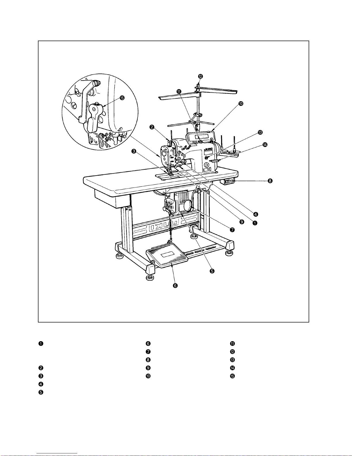
2. Name of each component ............................................................................ 2
3. Model numbering sysytem .......................................................................... 3
(1) LH-4128 (without a thread trimmer) ..........................................................................3
(2) LH-4128-7•LH-4168-7•LH-4188-7 (with a thread trimmer)........................................4
4. Special notes for safe operation ................................................................. 5
5. Standard adjustment .................................................................................... 8
(1) Needle bar and feed dog ............................................................................................8
1) Initial position of the needle bar..........................................................................................................8
2) Adjustment of the right and left feed dog positions, height, and gradient.........................................10
3) Needle bar height .............................................................................................................................12
4) Needle clamp....................................................................................................................................14
5) Needle entry .....................................................................................................................................14
(2) Timing between the needle and the hook...............................................................16
1) Lift of the needle bar .........................................................................................................................16
2) Clearance between the needle and the blade point of the hook ......................................................16
3) Position of the needle and the blade point of the hook.....................................................................16
(3) Initial position of the bobbin case opening lever ..................................................18
(4) Standard adjusting position for the inner hook guide arm shaft.........................18
(5) Clearance between the throat plate and the bobbin case stopper ......................20
(6) Relation between the main shaft and the lower shaft ...........................................22
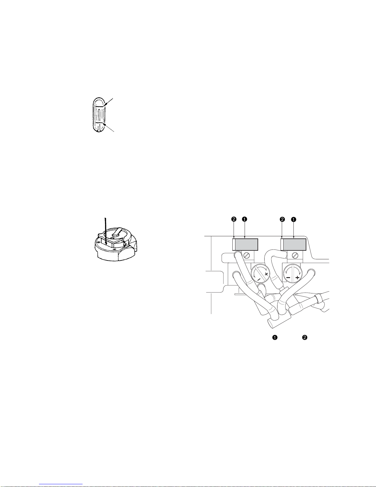
(7) Lubrication ................................................................................................................24
1) Lubrication system............................................................................................................................24
2) How to clean the filter section...........................................................................................................24
3) Hook oil amount................................................................................................................................24
4) Oil in the feed box.............................................................................................................................26
5) Replacement of the hook shaft oil wick ............................................................................................26
6) Replenishing grease to the specified places (for LH-4168-7, LH-4188-7 only) ................................28
(8) Forward and reverse stitch pitches ........................................................................32
(9) Adjusting the needle stop position.........................................................................34
1) Needle-up stop position of the sewing machine ...............................................................................34
2) Needle-down stop position of the sewing machine ..........................................................................34
(10) Disc release changeover for lap lifter.....................................................................36
(11) Needle bar stroke adjustment (for LH-4168-7, LH-4188-7 only) ...........................38
(12) Thread trimming device ...........................................................................................40
1) Moving knife position ........................................................................................................................40
2) Adjusting the height of the counter knife...........................................................................................40
3) Adjusting the thread presser spring ..................................................................................................42
4) Position of the thread trimming cam and the thread trimming timing ...............................................44
5) Clearance between the thread trimming cam and the thread loosening arm ...................................44
6) Adjustment of thread tension release ...............................................................................................46

(13) Wiper components....................................................................................................48
(14) Reverse solenoid position .......................................................................................48
(15) Initial position of the reverse feed control lever....................................................50
1) Auto-back..........................................................................................................................................50
(16) Assembling/adjusting the knee-lifter detecting device.........................................52
1) Assembling the knee-lifter detection sensor plate (asm.).................................................................52
2) Assembling the knee-lifter plate (asm.) ............................................................................................52
3) Connecting the cords........................................................................................................................54
4) Adjusting the knee-lifter detection seat (asm.)..................................................................................54
(17) Thread take-up lever guide position .......................................................................54
6. Separately driven needle changeover switch
(for LH-4168-7, LH-4188-7 only)................................................................. 56
7. Gauge replacing procedure ....................................................................... 57
8. Needle feed/bottom feed changeover....................................................... 59
9. Replacing the timing belt ........................................................................... 62
10.Installation/removal of the needle bar rocking base .............................. 64
11.Sewing specification.................................................................................. 66
12.List of gauge components ........................................................................ 67
(1) LH-4128......................................................................................................................67
(2) LH-4128F....................................................................................................................69
(3) LH-4128-7...................................................................................................................70
(4) LH-4168-7...................................................................................................................71
(5) LH-4188-7...................................................................................................................72
13. List of the major components.................................................................. 73
(1) List of expendable parts ..........................................................................................73
(2) Other renewal parts ..................................................................................................73
14. Troubles and corrective measures.......................................................... 74
15. Drawing of the table.................................................................................. 83

– 1 –
Application
No. LH-4128 LH-4128-7 LH-4168-7 LH-4188-7
(with automatic (with automatic thread (with automatic thread
thread trimmer) trimmer incorporating
trimming shuttle rectangular
corner stitching) stitching function)
1 Model Direct-drive, high speed, 2-needle, needle-feed, lockstitch machine
For light-, medium- and heavy-weight materials
Specification S: Standard
Specification F: Foundation
Specification G : Jeans
Specification G: Jeans
3Max. sewing speed 4000rpm (Specification F: 3000rpm) 3200 rpm
4Max. stitch length Forward/reverse feed: 5mm (Caution)1.
5Thread take-up Linked thread take-up lever
6Needle bar stroke 31.6mm 32.6mm
7Hook Small hook Large hook
8Not provided Provided
9Needle
Specification S : DP x 5 #9 to #16, Specification F : DP x 5 #9 to #11,Specification G : DP x 5 #16 to #22 (Caution) 2.
10 Gage size 1/8” to 1-1/2” 1/8” to 1-1/4” 1/8” to 1”
inch (mm) (3.2 to 38.1mm) (3.2 to 31.8mm) (3.2 to 25.4mm)
11 Lift of presser foot 12mm by knee lifter, 5.5mm by hand lifter lever, 9mm by knee lifter with wiper
12 Lubricating oil JUKI NEW Defrix oil No. 1 (equivalent ISO VG7)
JUKI grease A (Part No. : 40006323)
JUKI grease B(Part No. : 40013640)
14 Control box used SC910A -AA (Caution) 3.
15 External dimensions Width: 615mm, Heigh: 420mm, Depth: 267mm (with AK125)
16 Weight of head 65kg (LH-4168-7/AK125)
17 Power consumption 650VA
18 Temperature : 5°C to 35°C, Humidity : 35% to 85% (no condensation)
19 Rated voltage ±10%, 50/60Hz
20 Approx. 83dB A
Shipping voltage classification
3100 to 120V
4200 to 240V
1. Specifications
(Caution) 1. 4 mm only in the case of Specification F. For other Specifications S and G, 4 mm of normal/reverse feed
stitching is applicable to a maximum sewing speed of 3500 rpm or above.
2. For Specification F, the recommendable needle shall be of 134SES SERV7 Nm65 (equivalent to #9).
3. The control box , , and to be used shall be selected according to the classification specified below.
Model name
Item
Working temperature/
humidity
Supply voltage/
frequency
Separately driven needle
stop mechanism
Control box classification
S JUS (LA): single-phase 100 to 120V PFL
DJUS/General export: 3-phase 200 to 240V PFL
KGeneral export: single-phase 200 to 240V PFL
NCE: single-phase 200 to 240V PFL
UChina: single-phase 200 to 240V PFL
13 Grease JUKI grease A (Part No. : 40006323)
2Application
Control box type classification
S LH-4128, 4128-7
A LH-4128, 4128-7, 4168-7, 4188-7
Audible sound level
(3000rpm)
For medium- and
heavy-weight materials
Specification S : Standard,
Specification G : Jeans

– 2 –
2. Name of each component
Separately driven needle Pedal Bobbin winder
changeover switch Knee patch Thread stand
(LH-4168-7, LH-4188-7 only) Power switch Oil supply opening
Thread take-up cover Hand switch Reverse feed control lever
Finger guard Operation panel Hand lifter lever
Thread tension controller
Control box

– 3 –
3. Model numbering system
(1) LH-4128 (without a thread trimmer)
123456789101112131415161718192021
LH4128 A0B —AA
7Classification for the head specifications
SSemi-dry head
Needle gauge classification
Model 4128S
Code Gauge size F S G
[mm (inch)]
B3.2 (1/8)
<
——
D4.8(3/16)
<<
—
F6.4 (1/4)
<<<
Q25.4 (1) —
<
—
11 to 12
Classification for wiper and auto-reverse feed
0B Without wiper, with auto-reverse feed
8Classification for the head specifications
FSpecification for foundation
S
Specification for medium heavy-weight materials
G
Jeans, specification for heavy-weight materials
13 Classification for attachment application
Standard throat plate, standard face plate,
and standard cloth presser
Taping throat plate and taping face plate
Presser with a guide
14 to 18 Classification of presser lifter
Space Not provided
AK125 Auto-lifter (Pedal drive)
*4selectable only for the sewing spec. classification F
1 only for the sewing spec. classifications S and G
*Standard marked by
<
20 Place of distination
AStandard
21 Accessoried type
AStandard
10 Classification for feed
ANeedle feed
9
1
4

– 4 –
(2) LH-4128-7•LH-4168-7•LH-4188-7(with a thread trimmer)
5 to 6 Classification for the model
28 2-needle lock stitch needle feed
2-needle lock stitch needle feed with rectan-
gular stitching function
Shuttle spec. for 2-needle lock stitch needle
feed with rectangular stitching function
Need gauge classification
4128S-7
4168S-7
Code Gauge size S G G
[mm (inch)]
F6.4 (1/4)
<< <
*For the LH-4188-7, setting shall be made only for G.
7Classification for the head specifications
SSemi-dry head
20 Place of distination
AStandard
21 Accessoried type
AStandard
8 Classification for the sewing specification
S
Specification for medium heavy-weight materials
G
Jeans, specification for heavy-weight materials
123456789101112131415161718192021
LH41 FA7WB —AA
Model 4188S-7
9
*Standard marked by
<
10 Classification for feed
ANeedle feed
12 to 13
Classification for wiper and auto-reverse feed
WB Without wiper, with auto-reverse feed
14 to 18 Classification of automatic presser lifter
Space Not provided
AK125 Auto-lifter (Pedal drive)
68
88

– 5 –
(1) For the LH-4128 models of sewing machine without a thread trimmer, the throat plate, feed dog and presser
foot developer for the LH3128, LH-512 and LH-515 are applicable. Furthermore, commercially available thread
trimmer, throat plate, feed dog and presser foot can also be used with them.
(2) The machine oil (JUKI New Deflex Oil No.1) shall be supplemented so that the level gauge remains in the range
between the upper and lower engraved marker lines of the oil tank.
4. Special notes for safe operation
Upper engraved maker line
Lower engraved maker line
(3) When the sewing machine is operated for the first time or when it is reused after a long time of storage, running-
in operation shall be carried out at a speed of 3,000rpm or below. At that time, a few drops of machine oil shall
be applied to the section indicated by the arrow.
(Caution) Never lubricate inside of the face plate section. (No lubrication is required because a grease
lubrication system is adopted.)
o Hook race surface (left and right) o Hook shaft base
*Apply a lubricant to Gears and Felt that is
located beside the gears.

– 6 –
(4) Hook differs with the type of sewing machine, i.e., the sewing machine with/without a thread trimmer. Be sure to
use a hook that is exclusively designed for the sewing machine head.
(5) How to pass the bobbin thread (The bobbin thread winding direction is indicated by the arrow.)
oLH-4128 Latch hook o LH-4168-7 Hook with a thread trimmer and an separately
o LH-4128-7 Latch hook with a thread trimmer driven needle
oLH-4188-7 Hook with a thread trimmer and an separately
driven needle
(6) When synthetic threads are used, the thread guide arm (asm.) for the thread stand (asm.) if the thread flaps
during sewing.
Thread guide arm (asm.)
Thread standing guide arm (asm.)

– 7 –
MEMO

– 8 –
1) Initial position of the needle bar
Conditions
o The needle bar is in the lowest dead point.
oFeed amount : Minimum
oLH-4128, LH-4128-7 o LH-4168-7, LH-4188-7
5. Standard adjustment
(1) Needle bar and feed dog
Standard Adjustment
Top surface of the throat plate Top surface of the throat plate
13.5±
0.1mm 14.1±
0.1mm

– 9 –
1) Initial position of the needle bar
1. Set the stitch dial at “Minimum” on the scale.
2. Turn the handwheel to bring needle bar to the lowest dead point.
3. Loosen the setscrew shown.
4. Adjust the inner dimension provided between needle bar and presser
bar to the specified dimension. Then, tighten screw .
(Caution) 1. Distance from needle bar to presser bar should
be the distance provided between the bottom end of
the presser bar and the bottom end of presser bar
lower bushing .
2. After the adjustment, the needle entry point in the
needle slot in the feed dog may change.
Adjustment Procedure Results of Improper Adjustment
When the stitch length is
maximized, the feed dog will
come in contact with the throat plate
.
oStitch skipping or needle
breakage will be caused.
oThread trimming failure will be
caused.

– 10 –
2) Adjustment of the right and left feed dog positions, height, and gradient
Conditions
oFeed amount : Minimum
oWhen the feed dog is in the hightest position of its stroke, it should rise 1 ±0.1mm from the top surface
of the throat plate .
Top surface of the throat plate
1
±
0.1mm
Feed base
Standard Adjustment
Feed base
Feed rocker shft
Clearance
Clearance
C
A
B
[LH-4188-7]
Horizontal
[LH-4128, 4128-7, 4168-7]

– 11 –
2) Adjustment of the right and left feed dog positions, height, and
gradient
oRight and left feed dog positions
1. In order to make the right and left clearances be uniformly balanced
between the hole of the throat plate and the feed dog , loosen the
feed base arm setscrew to move the feed base arm in the axial
direction. After adjustments, tighten the setscrew .
2. If the above-mentioned adjustments are insufficient, loosen the set-
screw of the feed dog and adjust the feed dog and the feed
bar until they become parallel to each other. Since then, tighten the
setscrew and adjust the horizontal positioning (adjustments of 1.
above) of the feed dog again.
(Caution) When the gauge is replaced, make right/left adjustments
of the feed dog .
oFeed dog height
1. Minimize the feed amount by rotating the feed adjusting dial.
2. Turn the hand wheel so that the feed dog is positioned to secure its
maximum protrusion from the throat plate .
3. Loosen the setscrew and rotate the vertical feed link shaft to
adjust the feed dog to 1 ±0.1mm from the upper face of the throat
plate . After adjustments, tighten the setscrew .
(Caution) 1. After adjustments, the needle location may be changed
in relation to the hole of the feed dog .
oFeed dog gradient
1. Remove the cap of the bed side face and loosen the feed bar shaft
setscrew . Turn the roulette section to adjust the gradient.
Standard adjustment
oLH-4128, LH-4128-7, LH-4168-7
Position where the engraved marking dot Cof the feed base arm
coincides with the engraved marking dot Bof the feed base arm shaft
. (Engraved marking dot Ais applicable to the LH-3500.)
oLH-4188-7
Engraved marker line horizontal
When the feed dog is positioned too
high:
oThe feed dog will come in
contact with the throat plate .
oThe stitch length will be larger
than the value indicated by the
scale on the stitch dial.
oIt can be a cause of thread
trimming deficiency.
When the feed dog is positioned too
low:
oThe pitches of stitches become
smaller than the graduations of
the feed adjusting dial.
oThe moving knife will come in
contact with the feed dog at
the time of thread trimming.
This can be a cause of trimmer
malfunction.
Adjustment Procedure Results of Improper Adjustment

– 12 –
3) Needle bar height
Conditions
o Needle bar should be in its lowest dead point.
oFeed amount : Minimum
oLH-4128
oLH-4128-7
oLH-4168-7
oLH-4188-7
Standard Adjustment
Meets with the upper
engraved marker line
Maker lines engraved
on the needle bar Needle bar
connection
Maker lines engraved
on the needle bar
Coinciding with the
uppermost engraved
marker line

– 13 –
3) Needle bar height
oLH-4128, LH-4128-7
1. Set stitch dial “Minimum”.
2. Turn the handwheel to bring needle bar to the lowest dead point.
3. Loosen the needle bar connecting setscrew .
4. Align the upper marker line engraved on the needle bar with the
lower end face of the needle bar rocking base and tighten the needle
bar connecting setscrew .
oLH-4168-7, LH-4188-7
1. Set the stitch dial at “Minimum”.
2. Turn the handwheel to bring needle bar to the lowest dead point.
3. Remove the cap , and loosen the setscrew .
4. Align the uppermost marker line engraved on the needle bar with
the lower end face of the needle bar rocking base and tighten the
tightening screw at a tightening torque of 5.9N•m (60kgf•cm).
(Caution) 1. After the adjustment, the needle entry point in the
needle slot in the feed dog may change.
2. When tightening the setscrew , make sure not to shift
the needle throwing drive arm in the direction of the
arrow.
(When the DPX17 is used)
While the DPX17 is used, the second engraved marking line from the
bottom of the needle bar shall be made to coincide with the lowest
face of the needle bar rocking base .
oChange in height of the needle
bar may result in stitch skipping
or thread breakage.
oIf the needle throwing drive arm
is shifted, this can be a cause
of needle bar torque or needle
bar lock-up.
Adjustment Procedure Results of Improper Adjustment

– 14 –
Standard Adjustment
5) Needle entry
Conditions
o Needle bar should be in the lowest dead point.
oFeed amount : Minimum
oThe needle should enter of the needle slot in
the feed dog.
Needle slot in the feed dog
4) Needle clamp
Conditions
oNeedle bar should be in
the lowest dead point.
oFeed amount : 2.5mm B
C
D
1.2mm
2.2mm
[Dimension for reference] Needle clamp height at the lower dead point of the needle bar
Throat plate mounting surface AA
o Spec. S•F o Spec. G
LH-4128, 4128-7 LH-4168-7 Spec.S LH-4168-7 Spec. G LH-4188-7
Dimension A 15.1±0.15mm 15.8±0.15mm 14.6±0.15mm 15.2±0.15mm
oLH-4128
oLH-4128-7
Feed bar
oLH-4168-7
oLH-4188-7
Throat plate mounting surface

– 15 –
5) Needle entry
oLH-4128, LH-4128-7
1. Minimize the feed amount by rotating the feed adjusting dial.
2. Turn the handwheel to bring needle bar to the lowest dead point.
3. Loosen the setscrew of the needle bar connection .
4. Turn the needle bar in the direction of the arrow to adjust so that the
needle enters the center of the needle slot in the feed dog . After
the adjustment, tighten the screw .
5. If needle is longitudinally dislocated in the needle slot in the feed
dog, loosen clamping screw in feed rocker and adjust the longitudinal
position of the needle by turning feed base arm in the direction of
the arrow. After the adjustment, tighten screw .
(Caution) 1. Do not change the needle bar height.
2. Do not loosen needle clamp .
oLH-4168-7, LH-4188-7
1. Minimize the feed amount by rotating the feed adjusting dial.
2. Turn the handwheel to bring needle bar to the lowest dead point.
3. Loosen clamping screws and .
4. Turn the needle clamp so that the needle enters the center of
the needle slot in the feed dog . After adjustments, tighten the
tightening screws and .
5. If the needle seems to be displaced forward or backward in the slot
of the feed dog, loosen the feed bar arm tightening screw to rotate
the feed base arm . After adjustments, tighten the feed bar arm
tightening screw .
(Caution) 1. Needle clamp can be turned in the clearance
provided between screw and the rightmost and
leftmost edges on the slot in the needle bar .
oStitch skipping and thread
breakage will be caused.
o Poorly tensed seam will result.
oWhen the feed dog has
elongated needle slots (2.2mm
x 3.2mm), the needle thread will
be loosened if the needles enter
the far end of the respective
elongated slots viewed from the
operator.
*If needle entry is performed on
the operator side at the time of
thread trimming, this can be a
cause of failure in thread
trimming.
Adjustment Procedure Results of Improper Adjustment
4) Needle clamp
1. Turn the hand wheel and align the engraved line "B", which is the third
one from the bottom of the needle bar, with the lower end of the needle
bar lower bushing . (A rise of 2.2m) At that time, the distance between
the upper end section of the needle hole and hook’s blade point is
1.2mm in standard practice.
2. The above-mentioned adjustments are required when the needle DPX5
is used. When using the DPX17 needle, adjustments of "C" and "D"
should be carried out.
3. If standard values cannot be secured, remove the needle clamp screw
and rotate the needle clamp by one turn for adjustment (the
amount of adjustment: 0.6mm). Otherwise, remove the spring hold
setscrew and rotate the spring hold by half turn (the amount of
adjustment: 0.3mm).

– 16 –
1) Lift of the needle bar
2) Clearance between the needle and the blade point of the hook
3) Position of the needle and the blade point of the hook
Condition
o The needle bar ascends from the lowest dead point of its stroke.
oFed amount (stitch length)
: 2.5mm (ForG type, it should besetat3.5mm)
(For F type, it should be set at 2mm)
(2) Timing between the needle and the hook
Standard Adjustment
0 to 0.05mm
Blade point of the hook
Needle guard of the hook
0.03 to 0.1mm
oLH-4128 o LH-4168-7
LH-4128-7 LH-4188-7
Application A (mm) B (mm)
S.G.F 2.2 1.2
B
Blade point
Center of the needle aligns with
the blade point of the hook.
Lift of the needle bar when the lower maker
line on the needle bar meets the bottom and
of the needle bar frame : A=2.2mm
Lift of the needle bar from the lowest
dead point of its stroke
A
This manual suits for next models
2
Table of contents
Other JUKI Sewing Machine manuals

JUKI
JUKI MO-6704D User manual

JUKI
JUKI DSC-245 User manual

JUKI
JUKI MF-7523 User manual

JUKI
JUKI AMB-289 Quick start guide

JUKI
JUKI MF-7524 User manual

JUKI
JUKI HZL-NX7 User manual

JUKI
JUKI DDL-8700L User manual

JUKI
JUKI HZL-70 series User manual

JUKI
JUKI LG-158 User manual

JUKI
JUKI PS-800SB-2850 Series User manual

JUKI
JUKI HZL - 353Z Series User manual

JUKI
JUKI AMS-210EN/IP-420 User manual

JUKI
JUKI LU-562 User manual

JUKI
JUKI LK-1850 Series User manual

JUKI
JUKI DU-140 User manual

JUKI
JUKI MO-2000 Series User manual

JUKI
JUKI HZL - 355Z Series User manual

JUKI
JUKI LH-3126F Installation guide

JUKI
JUKI TL-2200QVP Mini User manual

JUKI
JUKI DDL-9000 User manual