JUKI LH-3500A series User manual

INSTRUCTION MANUAL
LH-3500A Series

i
CONTENTS
1. SPECIFICATIONS............................................................................................................ 1
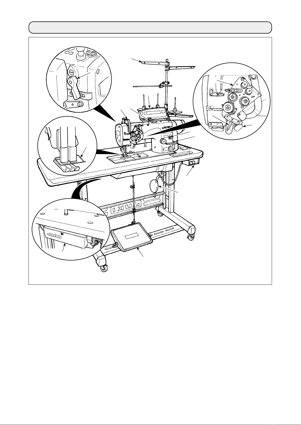
2. NAME OF EACH COMPONENT ..................................................................................... 3
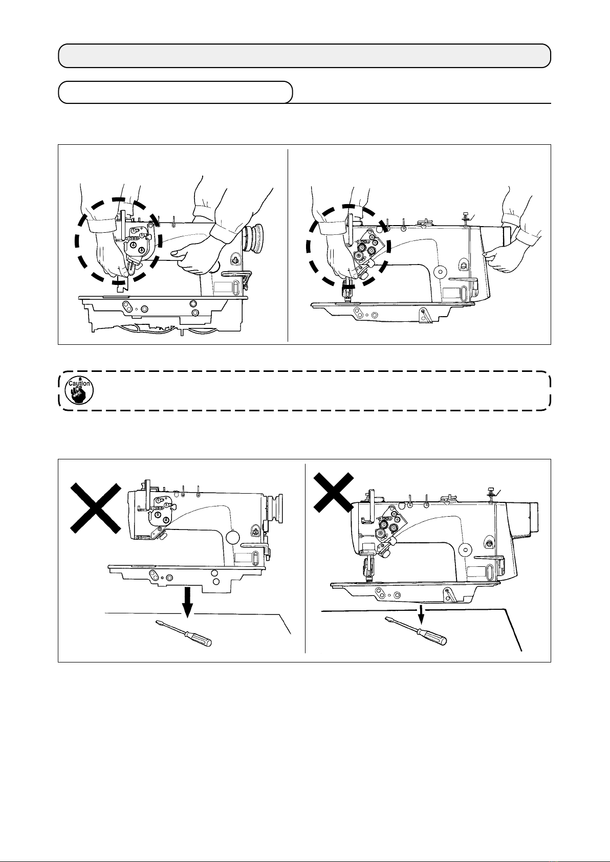
3. INSTALLATION................................................................................................................ 4
3-1. Caution at the time of set-up ................................................................................................................................ 4
3-2. Installation of the sewing machine ...................................................................................................................... 5
3-3. Adjusting the height of the knee lifter ................................................................................................................. 6
3-4. Installation of thread stand................................................................................................................................... 6
4. PREPARATION OF THE SEWING MACHINE ................................................................ 7
4-1. Method of lubrication ............................................................................................................................................ 7
4-2. Lubrication to the oil tank..................................................................................................................................... 8
4-3. Draining of oil from the oil tank............................................................................................................................ 9
4-4. Adjusting the amount of oil in the hook .............................................................................................................. 9
4-5. Oil in the feed box................................................................................................................................................ 10
4-6. Applying grease ................................................................................................................................................... 11
4-7. Setting up the SC-920.......................................................................................................................................... 14
4-8. Installing the belt cover (For LH-3528A, 3568A, 3578A and 3588A)................................................................ 18
4-9. Attaching the needles.......................................................................................................................................... 18
4-10. How to take out the bobbin case...................................................................................................................... 19
4-11. Inserting a bobbin in a bobbin case................................................................................................................. 19
4-12. Threading the machine head ............................................................................................................................ 20
4-13. Thread tension ................................................................................................................................................... 23
4-14. Winding the bobbin thread ............................................................................................................................... 24
4-15. Thread take-up spring ....................................................................................................................................... 25
4-16. Adjusting the stitch length................................................................................................................................ 27
4-17. Needle-to-hook relation..................................................................................................................................... 27
4-18. Pedal pressure and pedal stroke...................................................................................................................... 29
4-19. Adjustment of the pedal .................................................................................................................................... 29
5. OPERATION OF THE SEWING MACHINE .................................................................. 30
5-1. Pedal Operation ................................................................................................................................................... 30
5-2. Hand lifter ............................................................................................................................................................. 30
5-3. Adjusting the pressure of the presser foot ....................................................................................................... 31
5-4. Micro-lifter ............................................................................................................................................................ 31
5-5. Thread tension release changeover when using the knee lifter ..................................................................... 32
5-6. One-touch manual reverse feed (One-touch reverse feed type) ..................................................................... 32
6. MAINTENANCE............................................................................................................. 33
6-1. Procedure of changing over between bottom feed and needle feed and the adjustment
(for LH-3528A only) ............................................................................................................................................. 33
6-2. Changing the feed timing.................................................................................................................................... 35
6-3. Adjusting the thread trimming cam ................................................................................................................... 36
6-4. Adjusting the hook needle guard ....................................................................................................................... 37
6-5. Adjusting the inner hook guide .......................................................................................................................... 37
6-6. Adjusting the height and the inclination of the feed dog................................................................................. 38
6-7. Replacing the gauge............................................................................................................................................ 39
6-8. Adjusting the thread presser spring .................................................................................................................. 39
6-9. Adjusting the position of the moving knife ....................................................................................................... 40
6-10. Adjusting the counter knife position and the knife pressure ........................................................................ 41
6-11. Position of the wiper.......................................................................................................................................... 42
6-12. Caution when installing the attachments........................................................................................................ 42
6-13. Replacing the bobbin thread slack preventer spring (For LH-3568A, 3568A-7, 3588A and 3588A-7)........ 43
6-14. Stop of the needle bars and angle of corners for corners stitching
(For LH-3568A, 3568A-7, 3588A and 3588A-7) .................................................................................................. 43
7. STITCH-TO-ANGLE TABLE BY GAUGE (PITCH AND mm CONVERSION TABLE).. 44
8. GAUGE SETS................................................................................................................ 45
9. TROUBLES AND CORRECTIVE MEASURES ............................................................. 54
10. MOTOR PULLEY AND BELT ...................................................................................... 56

– 1 –
1. SPECIFICATIONS
Model name LH-3528A LH-3528A-7
(with automatic thread trimmer)
Application For light -, medium - and heavy - weight materials
S type : standard, F type : foundation, A type : light-weight materials, G type : jeans
Hook Standard hook Standard hook
Thread trimmer Not provided Provided
Separately
driven needle bar
mechanism
Not provided Not provided
Max. sewing speed
3,000 sti/min
Needle * 1 GROZ-BECKERT 134 Nm9 to Nm16 (For S, F and A types), 134 Nm16 to Nm23 (G type)
ORGAN needle DP x 5 #9 to #16 (For S, F and A types), DP x 5 #16 to #23 (G type)
Gauge size 3/32" to 1-1/2" 1/8" to 1-1/4"
2.4 to 38.1 mm 3.2 to 31.8 mm
Lift of presser foot 13 mm by knee lifter, 7 mm by hand lifter lever
Lubrication JUKI NEW DEFRIX OIL No. 1 or JUKI MACHINE OIL #7
Noise
Declaration
- Equivalent continuous emission sound
pressure level (LpA) at the workstation :
A-weighted value of 87.5 dB ; (Includes
KpA = 2.5 dB) ; according to ISO 10821-
C.6.2 -ISO 11204 GR2 at 3,000 sti/min.
- Sound power level (LWA) :
A-weighted value of 91.5 dB ; (Includes
KpA = 2.5 dB) ; according to ISO 10821-
C.6.2 -ISO 3744 GR2 at 3,000 sti/min.
Declaration
- Equivalent continuous emission sound
pressure level (LpA) at the workstation :
A-weighted value of 85.5 dB ; (Includes
KpA = 2.5 dB) ; according to ISO 10821-
C.6.2 -ISO 11204 GR2 at 3,000 sti/min.
- Sound power level (LWA) :
A-weighted value of 90.5 dB ; (Includes
KpA = 2.5 dB) ; according to ISO 10821-
C.6.2 -ISO 3744 GR2 at 3,000 sti/min.
Model name LH-3568A
(with incorporating corner stitching)
LH-3568A-7
(with automatic thread trimmer incorporating
corner stitching)
Application For light -, medium - and heavy - weight materials
S type : standard, G type : jeans
Hook Standard hook Standard hook
Thread trimmer Not provided Provided
Separately
driven needle bar
mechanism
Provided Provided
Max. sewing speed
3,000 sti/min
Needle * 1 GROZ-BECKERT 134 Nm9 to Nm16 (S type), 134 Nm16 to Nm23 (G type)
ORGAN needle DP x 5 #9 to #16 (S type), DP x 5 #16 to #23 (G type)
Gauge size 1/8" to 3/4"
3.2 to 19.1 mm
Lift of presser foot 13 mm by knee lifter, 7 mm by hand lifter lever
Lubrication JUKI NEW DEFRIX OIL No. 1 or JUKI MACHINE OIL #7
Noise
Declaration
- Equivalent continuous emission sound
pressure level (LpA) at the workstation :
A-weighted value of 83.5 dB ; (Includes
KPA = 2.5 dBA) ; according to ISO 10821-
C.6.2 -ISO 11204 GR2 at 3,000 sti/min.
- Sound power level (LWA) :
A-weighted value of 87.5 dB ; (Includes
KpA = 2.5 dBA) ; according to ISO 10821-
C.6.2 -ISO 3744 GR2 at 3,000 sti/min.
Declaration
- Equivalent continuous emission sound
pressure level (LpA) at the workstation :
A-weighted value of 84 dBA ; (Includes
KPA = 2.5 dB) ; according to ISO 10821-
C.6.2 -ISO 11204 GR2 at 3,000 sti/min.
- Sound power level (LWA) :
A-weighted value of 88.5 dBA ; (Includes
KpA = 2.5 dB) ; according to ISO 10821-
C.6.2 -ISO 3744 GR2 at 3,000 sti/min.
* 1 : Needle used depends on the destination.

– 2 –
Model name LH-3578A LH-3578A-7
(with automatic thread trimmer)
Application For medium - and heavy - weight materials
G type : jeans
Hook Large hook Large hook
Thread trimmer Not provided Provided
Separately
driven needle bar
mechanism
Not provided Not provided
Max. sewing speed
3,000 sti/min
Needle * 1 GROZ-BECKERT 134 Nm16 to Nm23 (G type)
ORGAN needle DP x 5 #16 to #23 (G type)
Gauge size 3/16" to 1-1/12" 3/16" to 3/8"
4.8 to 38.1 mm 4.8 to 9.5 mm
Lift of presser foot 13 mm by knee lifter, 7 mm by hand lifter lever
Lubrication JUKI NEW DEFRIX OIL No. 1 or JUKI MACHINE OIL #7
Noise
Declaration
- Equivalent continuous emission sound
pressure level (LpA) at the workstation :
A-weighted value of 87.5 dB ; (Includes
KpA = 2.5 dB) ; according to ISO 10821-
C.6.2 -ISO 11204 GR2 at 3,000 sti/min.
- Sound power level (LWA) :
A-weighted value of 91.5 dB ; (Includes
KpA = 2.5 dB) ; according to ISO 10821-
C.6.2 -ISO 3744 GR2 at 3,000 sti/min.
Declaration
- Equivalent continuous emission sound
pressure level (LpA) at the workstation :
A-weighted value of 85.5 dB ; (Includes
KpA = 2.5 dB) ; according to ISO 10821-
C.6.2 -ISO 11204 GR2 at 3,000 sti/min.
- Sound power level (LWA) :
A-weighted value of 90.5 dB ; (Includes
KpA = 2.5 dB) ; according to ISO 10821-
C.6.2 -ISO 3744 GR2 at 3,000 sti/min.
Model name LH-3588A
(with incorporating corner stitching)
LH-3588A-7
(with automatic thread trimmer incorporating
corner stitching)
Application For medium - and heavy - weight materials
G type : jeans
Hook Large hook Large hook
Thread trimmer Not provided Provided
Separately
driven needle bar
mechanism
Provided Provided
Max. sewing speed
3,000 sti/min
Needle * 1 GROZ-BECKERT 134 Nm16 to Nm23 (G type)
ORGAN needle DP x 5 #16 to #23 (G type)
Gauge size 3/16" to 3/8"
4.8 to 9.5 mm
Lift of presser foot 13 mm by knee lifter, 7 mm by hand lifter lever
Lubrication JUKI NEW DEFRIX OIL No. 1 or JUKI MACHINE OIL #7
Noise
Declaration
- Equivalent continuous emission sound
pressure level (LpA) at the workstation :
A-weighted value of 83.5 dB ; (Includes
KPA = 2.5 dBA) ; according to ISO 10821-
C.6.2 -ISO 11204 GR2 at 3,000 sti/min.
- Sound power level (LWA) :
A-weighted value of 87.5 dB ; (Includes
KpA = 2.5 dBA) ; according to ISO 10821-
C.6.2 -ISO 3744 GR2 at 3,000 sti/min.
Declaration
- Equivalent continuous emission sound
pressure level (LpA) at the workstation :
A-weighted value of 84 dBA ; (Includes
KPA = 2.5 dB) ; according to ISO 10821-
C.6.2 -ISO 11204 GR2 at 3,000 sti/min.
- Sound power level (LWA) :
A-weighted value of 88.5 dBA ; (Includes
KpA = 2.5 dB) ; according to ISO 10821-
C.6.2 -ISO 3744 GR2 at 3,000 sti/min.
* 1 : Needle used depends on the destination.

– 3 –
2. NAME OF EACH COMPONENT
❶Separately driven needle changeover lever
(LH-3568A, 3568A-7, 3588A, 3588A-7)
❷Thread take-up cover
❸Finger guard
❹Thread tension controller
❺Control box
❻Pedal
❼Knee pad
❽Power switch
❾Reverse feed switch
(LH-3528A-7, 3568A-7, 3528A (F type), 3578A-
7, 3588A-7)
Operation panel
Bobbin winder
Thread stand
Oil supply opening
Reverse feed control lever
Hand lifter lever
❷
❻
❽
❼
❸
❶
❹
❾
❺

– 4 –
3. INSTALLATION
(1) Transporting procedure of the sewing machine
Do not put protruding articles such as the screwdriver and the like at the location where the sewing machine
is placed.
3-1. Caution at the time of set-up
(2) Caution when placing the sewing machine
[LH-3528A, 3568A, 3578A, 3588A] [LH-3528A-7, 3568A-7, 3578A-7, 3588A-7]
Hold and transport the sewing machine with two persons as shown in the illustration.
When carrying the sewing machine, take extreme care not to hold the thread tension controllers
by hand. (If you hold the thread tension controllers by hand, they can break.)

– 5 –
3) Mount rubber hinge seats ❼ on the table and x the
table with nails.
Insert hinge ❻into the machine main body. Engage the hing-
es with rubber hinge seats ❼mounted on the table. Then,
put the machine head down on the machine head cushions
❽which are located at the four corners of the table.
3-2. Installation of the sewing machine
1) The under cover should rest on the four corners
of the machine table groove.
2) Fix two rubber seats ❶on side A(operator’s
side) using nails ❷as illustrated above. Fix two
cushion seats ❸on side B(hinged side) using a
rubber-based adhesive. Then place under cover
❹ on the xed seats.
(1) Installing the under cover
5) Detach inlet port for circulation which is xed on the feed box cover. Insert the inlet port into lter
until it will go no further without fail and place them in opening C.
Place urethan lter on D, and place lter of thin plate type (small mesh plate) on it.
❶
❷
❹
❸
AB
22.5mm
❶
❸
❶
❸
18.5mm
❻❻
❼
❾
❽
❼
4) Attach head support rod ❾to the table.
C
D
Circulation trouble may occur unless inlet port for circulation is securely inserted into ler
until it goes no further.

– 6 –
3-3. Adjusting the height of the knee lifter
1) The standard height of the presser foot lifted using the knee lifter is 12 mm.
2) You can adjust the presser foot lift up to 13 mm using knee lifter adjust screw ❶.
3-4. Installation of thread stand
Assemble the thread stand, set it up on the machine
table using the installation hole in the table and tight-
en nut ❶gently.
When you use power supplied by the overhead pow-
er line, pass the power supply cord through hollow
spool rest rod ❷.
WARNING :
To protect against possible personal injury due to abrupt start of the machine, be sure to start the
following work after turning the power o and ascertaining that the motor is at rest.
❷
❸
❶
300 mm from the top
surface of table
❷
❶
Do not operate the sewing machine in the state that the presser foot ❸is lifted by 12 mm or
more since the needle bar ❷comes in contact with the presser foot ❸.

– 7 –
4-1. Method of lubrication
For this sewing machine, one of two dierent lubricating methods can be selected.
(2) Method of non-circulation type lubrication (when only the clean oil is always used)
To ensure the long service life of the sewing machine, be sure to clean up the aforementioned
lter sections (at four locations) periodically (approximately once three months). When the lter
is clogged, lubrication trouble will occur and break-down will be caused.
In addition, when the oil becomes dirty, replace the oil gathered in the oil tank and the under cov-
er.
Insert inlet port ❶for circulation into section ❸of
the feed box cover until it will go no further to put it
into the state as it has been delivered to your plant.
* Drain oil dropped into the under cover by remov-
ing drain screw ❷.
Filter for
circulation
Urethan lter
Plunger
4. PREPARATION OF THE SEWING MACHINE
Circulation
Lubrication to
hook side
❷
❶
❸
Filter for plunger
Lubrication
Oil tank
Ball oat case
Oil inlet lter
Reux oil
from hook
(1) Method of circulating lubrication (when the oil collected in the under cover is reused)
When inlet port for circulation ❶comes
in contact with the oil surface, oil is
absorbed without passing the lter. As a
result, break-down will be caused.
If inlet port ❶for circulation is not insert-
ed into the feed box cover, oil may leak
from inlet port ❶for circulation or the
quantity of oil in the hook may uctuate.

– 8 –
4-2. Lubrication to the oil tank
Fill the oil tank with oil for hook lubrication before
operating the sewing machine.
1) Remove oil hole cap ❶ and ll the oil tank with
JUKI NEW DEFRIX OIL No.1 (Part No. : MD-
FRX1600C0) or JUKI MACHINE OIL #7 (Part
No. : MML007600CA) using the oiler supplied
with the machine.
2) Add oil until the top end of oil amount indicating
rod ❸does not go above the upper engraved
marker line.
If the oil tank is lled with an excessive amount
of oil, oil will leak from the air vent hole in the ball
oat case or proper lubrication will not be carried
out. So, be careful.
3) When you operate the sewing machine, rell oil if
the top end of oil amount indicating rod ❸comes
down to the lower engraved marker line of oil
amount indicating window ❷.
WARNING :
1. Do not connect the power plug until the lubrication has been completed so as to prevent
accidents due to abrupt start of the sewing machine,
2. To prevent the occurrence of an inammation or rash, immediately wash the related portions if
oil adheres to your eyes or other parts of your body.
3. If oil is mistakenly swallowed, diarrhea or vomitting may occur. Put oil in a place where children
cannot reach.
❸
❷
❶
• For the rst time you ll the oil tank with oil, add 280 cc of oil as a guide and check to be sure
that the oil amount indicating rod works. If the oil amount indicating rod does not work, bring it
to the workable state by tiling the sewing machine once.
• When you use a new sewing machine or a sewing machine after an extended period of disuse,
use the sewing machine after performing break-in at 2,000 sti/min or less.
• For the oil for hook lubrication, purchase JUKI NEW DEFRIX OIL No. 1 (Part No. : MD-
FRX1600C0) or JUKI MACHINE OIL #7 (Part No. : MML007600CA).
• Be sure to lubricate clean oil.
In case of the circulation type lubrication method, when using the sewing machine for the rst
time, the oil amount in the oil tank decreases until the oil has collected in the ler for circulation.
When the top end of oil amount indicating rod is lower than the lower engraved marker line, add
the oil to the oil tank again so that the top end enters between the upper and lower engraved
marker lines.
Lower
engraved
marker line
Upper
engraved
marker line

– 9 –
Adjust the amount oil using adjusting screw ❶. Turn screw ❶clockwise to increase the amount of oil in the
hook or counterclockwise to decrease it. Measure the amount of oil in ve seconds. When the amount of oil
is excessively decreased, break-down will be caused. So, be careful.
Oil splashes
Oil amount
decreases
Oil amount
increases
WARNING :
To protect against possible personal injury due to abrupt start of the machine, be sure to start the
following work after turning the power o and ascertaining that the motor is at rest.
4-3. Draining of oil from the oil tank
When draining oil from the oil tank, loosen and re-
move oil conrming window ❶.
WARNING :
1. To prevent accidents caused by abrupt start of the sewing machine, do not connect the power
plug until draining of oil has been completed.
2. To prevent the occurrence of an inammation or rash, immediately wash the related portions if
oil adheres to your eyes or other parts of your body.
3. If oil is mistakenly swallowed, diarrhea or vomitting may occur. Put oil in a place where children
cannot reach.
❶
❶
4-4. Adjusting the amount of oil in the hook
Oil may burst out from the oil conrming
window at the time of draining.
It is recommended, in this case, only to
loosen the oil conrming window instead
of removing it. Then, drain oil while con-
trolling the oil amount bursting out from
the oil amount conrming window ❶.

– 10 –
To use in safety, replace the oil wick of hook section with a new one approximately once a year
with the procedure below.
1) Loosen setscrews ❷(small hook : 2 places,
large hook : 3 places) and remove hook gib ❶.
When strongly pressing oil wick ❺, it
may be broken. Lightly insert it to such
an extent that it is not drawn out.
When loosening/assembling, do not allow
the slit section of oil plug ❹to be burred.
2) Remove inner hook ❸.
3) Loosen oil plug ❹with the L-shaped screwdriver
(Part No. : B9101490000) and remove it.
4) Draw out oil wick ❺inserted into oil plug ❹, and
replace it with a new one.
[Part No. of oil wick ❺]
After the replacement, assemble oil plug ❹,
inner hook ❸and hook gib ❶to the hook by
reversing the above procedure.
Perform conrming of oil splash.
❶
❷
❹
❺
❸
4-5. Oil in the feed box
When using the sewing machine, make sure that the
oil is put in the feed box from oil conrming window
❶.
❶
Small hook / Large hook 11015906
Oil Q’ty in the hook is largish 11404704
If you nd abnormal discoloring of oil
or dust in the oil through the oil amount
indicating window, loosen the window to
drain oil and ll the oil tank with new oil.

– 11 –
• Never lubricate oil to the grease applying places.
• When grease is applied more than is necessary, there is a fear that grease leaks from the thread
take-up lever cover section or the needle bar. So, be careful.
• Be sure to use the grease contained in JUKI GREASE A TUBE (Part No. : 40006323) supplied
with the machine head as accessories.
4-6. Applying grease
To use the sewing machine in safety, periodically perform grease-up (standard is once in 2 to 3 years) to the
grease applying sections of the respective models with the cotton bar or the like. When using SC-920, when
the time of grease-up comes, the warning alarm sounds. When the alarm sounds, perform grease-up.
[LH-3528A, 3528A-7, 3578A, 3578A-7]
WARNING :
To protect against possible personal injury due to abrupt start of the machine, be sure to start the
following work after turning the power o and ascertaining that the motor is at rest.
Thread take-up
lever (oil wick)
Needle bar
(1) Sections to be applied with grease
Remove wiper cover ❶, and apply grease to slot section ❷of wiper solenoid base and wiper link collar ❸.
❶
❷
❸
[LH-3528A-7, 3568A-7, 3578A-7, 3588A-7]
Square block
Face plate
lubrication felt

– 12 –
Remove the rubber cap, take out the felt in A, pour
new grease in the hole, and put the felt to which
grease has been soaked after removing old grease
adhered to the inside of the hole and the felt.
Further, pour grease above the felt and cover it with
the rubber cap.
[LH-3568A, 3568A-7, 3588A, 3588A-7]
[Common]
A
Thread take-up
lever (oil wick)
Needle bar bracket
Needle bar
Square block
Felt
Face plate
lubrication felt

– 13 –
❺
❻
❶❷ ❸ ❹
❺
❻
❶❷ ❸ ❹
(2) Releasing procedure of the grease-up warning for SC-920
When the time of grease-up has
come, screen display of LED ❺on
the left-hand gure becomes "E220".
After performing grease-up, release
the warning following the procedure
below.
WARNING :
To avoid possible personal injuries caused by movement other than that you desired, do not operate
the switches in the procedure other than those required, as described below, to specify the functions.
1) Turn OFF the power to the unit.
2) Pressing switch ❹, turn ON
the power to the unit.
3) When the screen is displayed,
keep switch ❹held pressed
for three seconds until the buzzer
sounds twice.
4) Set the setting No. ❻to "118".
When you want to advance the
setting No. ❻, press switch
❷to advance the setting No. ❻
When you want to return the set-
ting No. ❻, press switch ❶
to return the setting No. ❻
❺
❻
❶❷ ❸ ❹
Keep pressing switch ❷or switch ❶, and the setting No. ❻will advance (return)
continuously. If the setting No. ❻is moved forward (or backward), the previous (or subsequent)
content of the setting is conrmed. Be careful when the content of a setting is changed (when
the up / down switch is touched).

– 14 –
❺
❻
❶❷ ❸ ❹
(3) Releasing procedure of the grease-up “error” For SC-920
When using the machine for a certain period of time after the display of error No. 220 (continuing using the
machine without performing grease-up at the time of displaying No. 220), error No. 221 is displayed and the
machine stops running.
In this case, apply grease to the specied sections, then reset the error according to the description given in
"(2) Releasing procedure of the grease-up warning for SC-920" p.13
After completion of the operation, turn the power OFF and re-turn it ON to restore the normal operation.
5) When setting No. ❻is adjusted
to "118", the current set value is
displayed on LED ❺. Then Press
switch ❹(switch ❸) to
change to "1".
6) When the change has been com-
pleted, press switch ❷or
❶to specify the changed value.
4-7. Setting up the SC-920
Supply voltage 3-phase 200 to 240V
Frequency 50Hz/60Hz
Operating envi-
ronment
Temperature : 0 to 40˚C
Humidity : 90% or less
Input 320VA
(1) Specications
(2) Installing on the table (LH-3528A-7, 3568A-7, 3578A-7 and 3588A-7)
After completion of the operation, turn the power OFF and re-turn it
ON to restore the normal operation.
1) Hammer decoration bolt ❶supplied with the LH-
3500A into table.
The decoration bolt supplied with the SC-
920 is not used.
❶
Parts supplied with SC-920
Parts supplied with LH-3500A
❻
❼
❹
❸
❶
❽
❾
×
Table
Operator side
When turning OFF the pow-
er before performing this
work, the contents which
have been changed are not
updated.

– 15 –
❻
❼
❹
❸
❷
❽
❾
❶A
❶B
❶
❶B
❹
❺
❻
❹
❺
❻
❹
❺
❻
Table
2)
Fix rubber cushion ❻on control-box mounting plate
❸with nut ❹and spring washer ❼. Three sets of
❷are required.
4) Place the SC-920 on rubber cushions ❻ and x
with nuts ❹and washers ❺.
Install the control box while carefully changing the
position of the temporarily-xed control-box mounting
plate (right one as observed from the worker).
1. If you use the decoration bolt supplied
with the SC-920, the control box cannot
be installed since the bolt interferes with
the control box.
2. If the control-box mounting plates are
xed on the table in a wrong installing
direction or with the hole located at a
wrong position, the control box cannot
be installed.
Away from the
operator side
Away from the
operator side
3) Fix control-box mounting plates ❷assembled
in step 2) on the table with decoration bolts ❶,
washers ❽, spring washers ❾and nuts .
Screw
❶A
at one location this side as observed
from the operator should be securely tightened,
and two screws ❶B
at two locations far side
from the operator should be temporarily tight-
ened.
* Install control-box mounting plate ❸as illustrat-
ed in the gure, carefully checking the installing
direction and the location of holes.
* The washers, spring washers and nuts supplied
with the SC-920 should be used.
Operator side

– 16 –
(3) Setting procedure of the machine head
1) Call function setting No. 95 referring
to "#-6. Setting functions of SC-
920" in the Instruction Manual for the
SC-920.
2) The type of machine head can be
selected by pressing switch
❸
( switch
❹
).
* Refer to "CAUTIONS WHEN SET-
TING UP THE SEWING MACHINE"
or "Machine head list" on the sepa-
rate sheet for the types of machine
heads.
3) After selecting the type of machine
head, by pressing switch ❶
( switch ❷), the step proceeds
to 96 or 94, and the display automat-
ically changes to the contents of the
setting corresponding with the type
of machine head.
❺
❻
❶❷ ❸ ❹
❺
❻
❶❷ ❸ ❹
❺
❻
❶❷ ❸ ❹
For the operation panel other than CP-18, refer to the Instruction Manual for the operation panel
to be used for the setting procedure of the machine head.

– 17 –
❼
❽
(4) Adjusting the machine head (LH-3528A-7, 3568A-7, 3578A-7 and 3588A-7)
When the slip between the white marker dot on the handwheel and the concave of the cover is
excessive after thread trimming, adjust the angle of the machine head by the operation below.
1) Simultaneously pressing
switch ❷and switch ❸, turn
ON the power switch.
2) is displayed ( ❻) in the in-
dicator and the mode is changed
over to the adjustment mode.
3) Turn the pulley of the machine
head by hand until the main-shaft
reference signal is detected. At
this time, the degree of an angle
from the main-shaft reference sig-
nal is displayed on the indicator
❺. (The value is the reference
value.)
4) In this state, align the white dot ❼of the hand-
wheel with the concave ❽of the pulley cover as
shown in the gure.
5) Press switch ❹ to nish the
adjustment work. (The value is the
reference value.)
❺
❻
❶❷ ❸ ❹
❺
❻
❶ ❷ ❸ ❹
❺
❻
❶❷ ❸ ❹

– 18 –
4-9. Attaching the needles
Switch "o" the motor.
Use DPx5(134) needles.
1) Turn the handwheel until the needle bar has
come up to the highest point of its stroke.
2) Loosen needle clamp screws ❷and pick up two
needles ❶in the way that their grooves ❸are
facing outwards.
3) Insert the needles into the needle clamp as far
as they will go.
4) Tighten needle clamp screws ❷ rmly.
4-8. Installing the belt cover (For LH-3528A, 3568A, 3578A and 3588A)
1) Drill guide holes Aand Bof wood screws in the table.
2) Temporarily x belt cover B ❶to the place of guide holes Aand B.
3) Install belt cover A ❷to the arm installing section.
4) Adjust the position of belt cover B ❶ and x it with wood screw.
WARNING :
To protect against possible personal injury due to abrupt start of the machine, be sure to start the
following work after turning the power o and ascertaining that the motor is at rest.
WARNING :
To protect against possible personal injury due to abrupt start of the machine, be sure to start the
following work after turning the power o and ascertaining that the motor is at rest.
❶
❷
AB
67
(mm)
47
LH-3528A, 3568A
LH-3578A, 3588A
[LH-3568A, 3568A-7, 3588A and 3588A-7]
❸
❸
❶
❷
❷
❶
❶
❷
❷
❶
[LH-3528A(A type and F type)]
[LH-3528A(S type and G type), 3528A-7, 3578A and
3578A-7]
❶
❷
❷
❶
❸
Other manuals for LH-3500A series
2
This manual suits for next models
6
Table of contents
Other JUKI Sewing Machine manuals

JUKI
JUKI MBH-180 Quick start guide

JUKI
JUKI HZL-60 CE User manual

JUKI
JUKI NA-11UT Series User manual

JUKI
JUKI PLC-1690 User manual

JUKI
JUKI MO-734DE User manual

JUKI
JUKI IP-110 Type F User manual

JUKI
JUKI MO-50e User manual

JUKI
JUKI LH-3126F Installation guide

JUKI
JUKI LK1903B/BSS302 User manual

JUKI
JUKI LK-1910 User manual

JUKI
JUKI DLN-415 User manual

JUKI
JUKI CP-160 User manual

JUKI
JUKI PLK-J6040R User manual

JUKI
JUKI LBH-1795A User manual

JUKI
JUKI LU-2810-6 User manual

JUKI
JUKI DDL-9000 Quick start guide

JUKI
JUKI DLN-6390 User manual

JUKI
JUKI AMS-221EN Series Quick start guide

JUKI
JUKI DDL-9000 User manual

JUKI
JUKI DDL-8700-7 User manual