JUKI SC-920 Quick start guide

SC-920
®
40089311
No.E393-00
ENGINEER’S MANUAL

PREFACE
This Engineer’s Manual is written for the technical personnel who are responsible for the service and maintenance
of the machine.
The Instruction Manual for these machines intended for the maintenance personnel and operators at an apparel
factory contains operating instructions in detail.
It is advisable to use the Instruction Manual and Parts List for CP-180, IP-110F, SC-920 together with this
Engineer's Manual when carrying out the maintenance of these machines.
This manual gives the "Standard Adjustment" on the former section under which the most basic adjustment value
is described and on the latter section the "Results of Improper Adjustment" under which stitching errors and
troubles arising from mechanical failures and "How To Adjust" are described.

CONTENTS
1. SPECIFICATION ............................................................................................................ 1
2. OUTLINE .......................................................................................................................... 1
(1) Features ........................................................................................................................1
3. NAME OF EACH COMPONENT................................................................................ 2
(1) DDL-9000B/SC-920 ......................................................................................................2
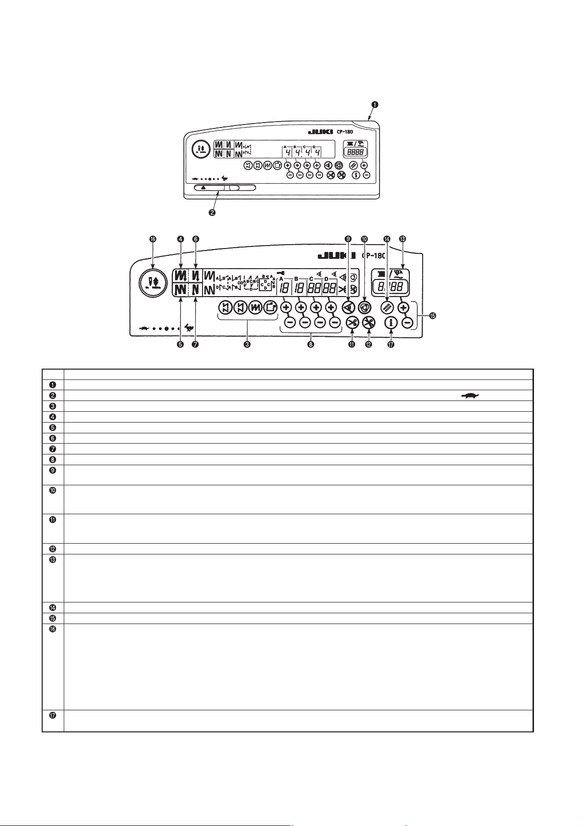
4. EXPLANATION OF OPERATION PANEL .............................................................. 4
(1) List of operation panels of CP-180..............................................................................4
(2) List of operation panel of IP-110F ..............................................................................5
(3) Operation of the connection panel..............................................................................7
1) Connecting procedure of CP-18/180 or IP-110F.................................................................. 7
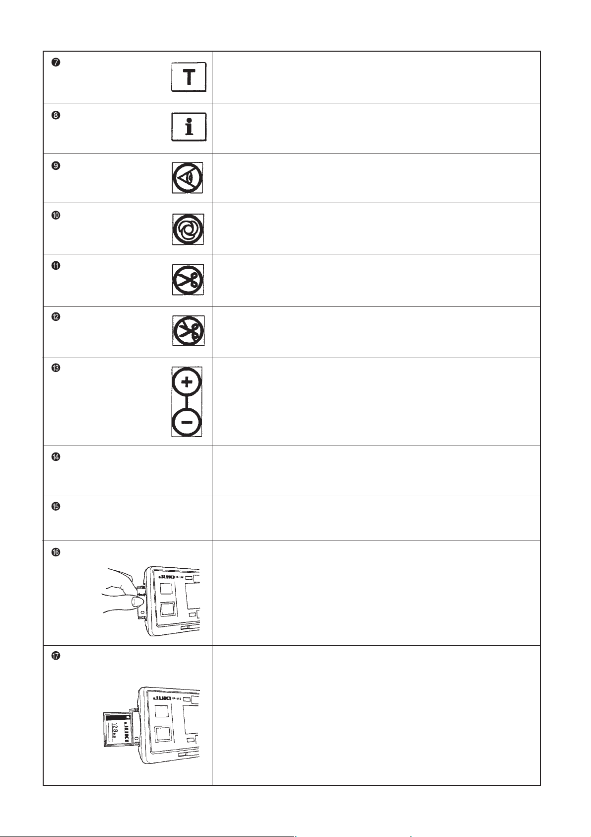
(4) Explanation of operation panel CP-180 ......................................................................8
(5) Example of application ..............................................................................................12
(6) Explanation of operation panel IP-110F....................................................................15
1) Information.................................................................................................................. 17
2) Error code list (Error display in panel) ............................................................................ 26
3) Warning list ................................................................................................................ 29
5. CONTROL BOX (SC-920).......................................................................................... 30
(1) Connecting the cords ................................................................................................30
(2) Operating procedure ..................................................................................................31
(3) Explanation of the operation panel (CP-18)..............................................................32
(4) Operating procedure of the sewing pattern ............................................................33
(6) Setting for functions ..................................................................................................36
(5) One-touch setting ......................................................................................................35
(7) Setting procedure of the machine head....................................................................37
(8) Machine head list ........................................................................................................38
(9) Adjusting the machine head (Direct-drive motor type sewing machine only)......39
(10) Function setting list..................................................................................................40
(11) Detailed explanation of selection of functions ......................................................44
1) Reverse stitching pattern ................................................................................................ 8
2) Constant-dimension stitching pattern .............................................................................. 9
3) Overlapped stitching pattern ........................................................................................ 10
4) Rectangular stitching pattern ........................................................................................ 11
1) Reverse stitching pattern .............................................................................................. 33
2) Constant-dimension stitching pattern ............................................................................ 34
6. CONNECTING PROCEDURE OF JUKI OPTIONAL DEVICE ........................ 54
(1) Connection of the material end sensor (ED) ............................................................54
(2) Connection of the pedal of standing-work machine (PK) ......................................54
(3) Setting of the auto lifter function ..............................................................................54

8. INITIALIZATION OF THE SETTING DATA .......................................................... 56
9. CONNECTOR CONNECTION DIAGRAM ............................................................ 57
(1) Solenoid for machine head ........................................................................................57
(2) Solenoid for lifting presser foot ................................................................................57
10. OPTIONAL CORD .................................................................................................... 58
(1) Relay cord A asm. for the standing sewing machine (Part No. M9701351AA0) ..58
11. MAINTENANCE ........................................................................................................ 60
(1) Replacing the fuse ......................................................................................................60
(2) Method of voltage changeover ..................................................................................61
12. REGARDING ERROR DISPLAY (SC-920) ........................................................ 62
(1) Error code list (SC-920) ..............................................................................................64
13. BLOCK DIAGRAM .................................................................................................... 66
(1) SC-920 block diagram ................................................................................................66
(2) IP-110F operation panel block diagram ....................................................................67
14. DRAWING OF THE TABLE (For DDL-9000B).................................................. 68
7. EXTERNAL INPUT / OUTPUT CONNECTOR .................................................... 55

– 1 –
1. SPECIFICATIONS
Supply voltage Single phase 100 to 120V 3-phase 200 to 240V Single phase 200 to 240V
zH06/zH05zH06/zH05zH06/zH05ycneuqerF
Operating temperature range Temperature : 0 to 40°C Temperature : 0 to 40°C Temperature : 0 to 40°C
Operating humidity range Humidity : 90% or less Humidity : 90% or less Humidity : 90% or less
Power consumption 320VA 320VA 320VA
Mass 3kg 3kg 3kg
2. OUTLINE
(1) Features
1) Voltage changeover function of single phase 100 to 120V/3-phase 200 to 240V is provided.
The control box with voltage changeover function can be used either for single phase 100 to 120V or for 3-
phase 200 to 240V by replacing the power cord up to the power switch and changing the voltage changeover
connector inside the box.
In addition, it can be used for single phase 200 to 240V.
2) By using IP-110F, CP-180 the sewing management information such as output display, etc. can be used.
3) The conventional JUKI optional devices can be used without any adjustment.
However, when AE (bobbin thread remaining amount detection device) is used, it is necessary to separately
purchase the optional circuit board.
4) By using the flash ROM for CPU, the future version-up can be adapted.
5) The SC-920 control box can be used for the (belt) drive system machine head by connecting the DD
(direct-drive) system machine head and the small-sized motor unit (M-92).

– 2 –
Power switch Knee lifter
Operation panel (CP-18, 180 or IP-110F) Oil filler port (except for DDL-9000B-DS)
Pulley cover Feed lever
Thread stand Minute adjustable presser lifting screw
Control box (SC-920) Hand wheel
Operation pedal Take-up lever cover
One-touch type reverse feed button Finger guard
Wiper Under cover
Bobbin winder unit 1st thread tension
Stitch dial 2nd thread tension
3. NAME OF EACH COMPONENT
(1) DDL-9000B/SC-920

– 3 –
Power switch
This switch turns on and off the power to the head unit motor, electric components, and operation panel.
Operation panel (CP-18, 180 or IP-110F)
This panel allows users to conduct the settings of automatic reverse stitching, head sewing, sewing speed, and
more.
Pulley cover
This cover protects the machine head motor.
Thread stand
Control box (SC-920)
The box contains the circuit that controls the head unit and motor, the output circuit that operates each output
(the thread trimming solenoid, back solenoid, wiper solenoid, etc.), the pedal sensor that detects the pedal
operation, and the power circuit that performs each function.
Operation pedal
This pedal allows users to conduct machine speed control, thread trimming, presser lifting motion (only for AK-
138), and more by depressing the front or back part of the pedal.
One-touch type reverse feed button
This button allows users to conduct reverse stitching.
Wiper
The wiper moves the needle from the sewing material after thread trimming under control of the wiper signal
from the control box.
Bobbin winder unit
This unit is integrated into the head unit.
Stitch dial
This dial adjusts the front feeding amount.
Knee lifter
Oil filler port (except for DDL-9000B-DS)
This port is used for lubrication to the hook. (except for DDL-9000B-DS)
Feed lever
This lever allows users to conduct reverse stitching.
Minute adjustable presser lifting screw
Hand wheel
Take-up lever cover
This cover prevents users from touching the take-up lever.
Finger guard
This guard prevents users (mainly thumb and fingers) from touching the needle.
Under cover
1st thread tension
2nd thread tension

– 4 –
4. EXPLANATION OF OPERATION PANEL
(1) List of operation panels of CP-180
noitpircseD.oN
Power indication LED : Lights up when the power switch is turned ON.
Max. speed limit variable resister : Maximum speed is limited when this resister is moved in the left direction ( ).
Pattern selector switch : Used for selecting a pattern from among the four different patterns.
Automatic double reverse stitching at the start of sewing switch : Used for turning ON / OFF the automatic double reverse stitching at the start of sewing.
Automatic double reverse stitching at the end of sewing switch : Used for turning ON / OFF the automatic double reverse stitching at the end of sewing.
Automatic reverse stitching at the start of sewing switch : Used for turning ON / OFF the automatic reverse stitching at the start of sewing.
Automatic reverse stitching at the end of sewing switch : Used for turning ON / OFF the automatic reverse stitching at the end of sewing.
Switches for setting the number of stitches : Used for setting the number of stitches to be sewn in processes A through D.
Material edge sensor ON / OFF switch : Rendered effective when the material edge sensor is installed on the machine.
Used for setting whether or not the material edge sensor is used during sewing.
One-shot automatic stitching switch :
Rendered effective when the material edge sensor is installed on the machine or when the sewing
machine is operated under the constant-dimension stitching mode. Start the sewing machine with this switch, and the sewing machine will run
automatically until the material edge is detected or the end of a constant-dimension stitching is reached.
Automatic thread trimming switch :
Rendered effective when the material edge sensor is installed on the machine or when the sewing
machine is operated under the constant-dimension stitching mode. Even keep depressing the front part of the pedal, the sensor can detect the
material edge, or after the completion of the constant-dimension stitching mode, the machine will automatically perform thread trimming.
Bobbin thread counter : Indicates the amount of bobbin thread while counting it by subtracting from the set value.
Bobbin thread counter/thread trimming counter : Bobbin thread counter/thread trimming counter can be changed over by the
function of the control box main body.
Bobbin thread counter : Indicates the amount detecting device is installed on the machine, the counter indicates the number of times
of detecting.
Thread trimming counter : Every time thread trimming is performed, the counter value is added.
Bobbin counter reset switch : Used for returning the value shown on the bobbin thread counter to the initial value.
Bobbin thread amount setting switch : Used for setting the amount of bobbin thread.
Needle bar stop position changeover function to be available when the needle up/down compensating switch/pedal is in
neutral state.
Needle up/down compensating switch : This switch is used for each needle up/down compensating stitching.
[Changeover selection of needle bar stop position when the pedal is in its neutral position]
Pressing the needle up/down compensation switch, turn ON the power to the machine, and the needle bar stop position when the pedal
is in its neutral position is changed over to down position/up position.
Confirmation of the stop position can be performed at the front cover of the control box.
When up position stop is specified : “ nP UP “
When down stop position is specified : “ nP Lo “
Information switch
Used for calling the production support function (by keeping the switch held pressed for one seconds).

– 5 –
(2) List of operation panel of IP-110F
Re-sewing switch This switch is used to continue sewing from the step on the way after
replacing bobbin thread when bobbin thread has run out during program
stitching step.
Needle up/down This is the switch to perform needle up/down compensating stitching.
compensating switch (Needle up/down compensating stitching and one stitch compensating
stitching can be changed over with function setting No.22.)
Screen changeover This is the switch to change over the screen.
switch
With/without reverse This is the switch to turn ON/OFF automatic reverse feed stitch at sewing start.
feed stitch at sewing * This switch cannot be used with the sewing machine which is not
.ecivedgnihctitsdeefesrevercitamotuahtiwdedivorphctiwstrats
With/without reverse This is the switch to turn ON/OFF automatic reverse feed stitch at sewing end.
feed stitch at sewing * This switch cannot be used with the sewing machine which is not
.ecivedgnihctitsdeefesrevercitamotuahtiwdedivorphctiwsdne
Reset switch This is the switch to make the value of bobbin thread counter or sewing
counter the set value.
Re-sewing switch Information switch Power display lamp
Needle up/down compensating switch Material edge sensor switch Media slot cover
Screen changeover switch One-shot stitching switch Media slot
With/without reverse feed stitch With/without automatic thread (Media inserting opening)
hctiwsremmirthctiwstratsgniwesta Compact flash (TM)
With/without reverse feed stitch Thread trimming prohibiting switch Optional :
at sewing end switch Counter value setting switch Part No.40000100
Reset switch Max. speed limitation variable resistor
Teaching switch
* “CompactFlash™ or CFA specification compatible media”.
* “CompactFlash™” is a registered trademark of SanDisk Corporation, U.S.A.
IP-110
*

– 6 –
Teaching switch This is the switch to set the setting of the number of stitches with the
value of number of stitches which has been actually sewn.
Information switch This is the switch to perform various function settings.
Material edge sensor Rendered effective when the material edge sensor is installed on the machine.
Uhctiws sed for selecting whether or not the material edge sensor is used during sewing.
One-shot stitching When this switch is set to effective at the time of program stitching, the
switch sewing machine automatically operates up to the specified number of
stitches.
With/without automatic When this switch is set to effective at the time of program stitching, the
thread trimmer switch sewing machine automatically performs thread trimming when the speci-
fied number of stitches has been completed.
Thread trimming This switch prohibits all thread trimmings.
prohibiting switch * This switch cannot be used with the sewing machine which is not provided
with the automatic thread trimming device.
Counter value setting This is the switch to set the value of bobbin thread counter of No. of pcs. counter.
switch
Max. speed limitation variable When moving the resistor in the left direction, max. speed is limited.
resistor
Power display lamp This lamp lights up when the power switch is turned ON.
Media slot cover This is the cover for media inserting opening.
To open the cover, place your finger on the notch located on the side of the cover
as shown in the figure and push the cover in the direction of left slanting rear.
* There are some functions that are not able to be operated with the cover opened.
Do not close the cover unless compact flash (TM) is completely inserted.
oTtolsaideM set compact flash (TM), place the label face of the compact flash (TM) to the
(Media inserting opening) front and insert the part that has a small hole (place the notch of the edge to the
rear) to the panel.
To remove the compact flash (TM), hold it between your fingers and draw
it out.
*When the inserting direction of the compact flash (TM) is wrong, the
panel and the compact flash (TM) may be damaged. Do not insert any-
thing other than the compact flash (TM).

– 7 –
(3) Operation of the connection panel
1) Connecting procedure of CP-18/180 or IP-110F
Exclusive connectors are prepared for connection of the
connector for CP-18/180, IP-110F.
Paying attention to the orientation of the connector, con-
nect it to connector CN38 located on the circuit board.
After connecting, securely lock the connector.
1. After inserting the connector, put all cords together
with cable clip band )
4
located on the side of the
box.
(Caution) 1. Fix the cord clamp and the cable clip
band )following the attaching
procedure.
2.
When removing the connector, re-
move it from the wire saddle and
remove it while pressing the hook of
the cable clip band ).
How to fix cable clip band ))
How to remove cable clip band
Pushing the hook portion, push the band to remove it.
Pull Push
Push the hook.
4
/
Panel Panel
)
[Connection of the connector for CP, IP panel]
(Caution) Be sure to turn OFF the power before
connecting the connector.

– 8 –
(4) Explanation of operation panel CP-180
1) Reverse stitching pattern
OFF ON OFF ON
OFF OFF ON ON
Sewing pattern
1. Press reverse stitching pattern switch to
specify the reverse stitching pattern.
2. The reverse stitching pattern is selected, and
the number of stitches and data on reverse
stitching which have already been specified are
shown on the panel.
3. If you want to change the number of stitches,
operate the " + " or " - " switch of switches for
setting the number of stitches A through D.
(The range of the number of stitches that can
be changed : 0 to 19 stitches)
4. Four different stitching patterns can be
performed by matching the ON and OFF settings
of automatic reverse stitching (for start) switch
and automatic reverse stitching (for end)
switch .
5. Furthermore, the double reverse stitching can
be selected by operating double reverse
stitching (for start) switch and double reverse
stitching (for end) switch .
A
B
D
C
D
C
A
B

– 9 –
2) Constant-dimension stitching pattern
OFF ON OFF ON
OFF OFF ON ON
Sewing pattern
4. Four different kinds of stitching patterns can be performed according to the combination of ON/OFF settings of
automatic reverse stitching (for start) switch and automatic reverse stitching (for end) switch .
5. Furthermore, the double reverse stitching mode can be specified by operating double reverse stitching (for start)
switch and double reverse stitching (for end) switch .
6. If automatic thread trimming switch is turned ON, the sewing machine will automatically perform thread
trimming after it finishes the predetermined number of stitches between C and D. (If the automatic reverse feed
stitching (for end) is selected, the sewing machine will automatically perform thread trimming after it finishes the
automatic reverse stitching (for end) even when the automatic thread trimming switch is not selected.)
If automatic thread trimming switch is turned OFF, operate the touch-back switch after the completion of
processes C and D. Then the machine runs at a low speed (stitch compensation operation).
Also, if the pedal is returned to its neutral position and depressed its front part again, the sewing can be continued
regardless of the setting of number of stitches.
7. If thread trimming prohibiting function is chosen, the machine will stop with the needle up without performing
thread trimming.
8. If one-shot automatic stitching function is chosen, the machine will automatically perform sewing at a stretch,
at the specified speed by depressing the front part of the pedal.
1. Press constant-dimension stitching pattern
switch on the control panel to select the
constant-dimension stitching pattern.
2. The constant-dimension stitching pattern is
selected. Now, the predetermined number of
stitches and the state of reverse stitching
function are shown on the control panel.
3. To change the number of stitches of the
processes in the constant-dimension stitching
pattern, change the number of stitches for
processes C and D by operating switches
for setting the number of stitches for processes
C and D. Select the reverse feed stitching
accordingly. To change the number of reverse-
feed stitches, operate switches for setting
the number of stitches for processes A and B.
Adjusting range : A, B = 0 to 19 stitches
C, D = 0 to 500 stitches
C
D
A
B
C
D
A
B
C
D
A
B
A
B
C
D

– 10 –
3) Overlapped stitching pattern
A
B
C
C
B
D
1. Press overlapped stitching pattern switch to
specify the overlapped stitching pattern.
2. The overlapped stitching pattern is selected, and
the number of stitches and data on overlapped
stitching which have already been specified are
shown on the panel.
3. If you want to change the number of stitches,
operate number of stitches setting switches
for processes A through C, and to change the
number of repeated processes, operate the
“ + “ or “ - “ switch of switch for setting the
number of processes D.
The range of the number of stitches A, B and
C that can be changed : 0 to 19 stitches.
The range of the number of processes D that
can be changed : 0 to 9 times.
4. Depress the front part of the pedal once, and the
sewing machine will repeat the normal stitching
and reverse stitching by the predetermined times.
Then, the sewing machine will automatically
make the thread trimmer actuate and will stop to
complete the overlapped stitching procedure.
(The one-shot automatic stitching cannot be
turned OFF.)
5. If thread trimming prohibiting function is
chosen, the machine will stop with the needle up
upon completion of the overlapped stitching
procedure without performing thread trimming.

– 11 –
4) Rectangular stitching pattern
OFF ON OFF ON
OFF OFF ON ON
Sewing pattern
1. Press rectangular stitching pattern switch on the control panel to select the rectangular stitching pattern.
2. The rectangular stitching pattern is selected. Now, the predetermined number of stitches and other sewing data
are shown on the control panel.
3. To change the number of stitches of the processes in the rectangular stitching pattern, operate switches (for
processes C and D) to change the number of stitches for processes C and D.
Select the reverse feed stitching accordingly. To change the number of reverse-feed stitches, operate switches
for setting the number of stitches for processes A and B.
(Adjustable range : A, B = 0 to 19 stitches, C, D = 0 to 99 stitches)
4. Four different kinds of stitching patterns can be performed according to the combination of ON/OFF settings of
automatic reverse stitching (for start) switch and automatic reverse stitching (for end) switch .
5. Furthermore, the double reverse stitching mode can be specified by operating double reverse stitching (for start)
switch and double reverse stitching (for end) switch .
When the touchback switch is operated at this time, the sewing machine runs at a low speed (compensating stitching). If the
automatic thread trimming switch is not specified, sewing can be continued regardless of the setting of the
number of stitches when the pedal is returned to its neutral position and its front part is depressed again after the
final step has been automatically stopped.
6. If automatic thread trimming switch is turned ON, the sewing machine will automatically perform thread trimming
after the completion of the last process. (If the automatic reverse stitching (for end) is selected, the sewing machine
will automatically perform thread trimming after it finishes the automatic reverse stitching (for end).)
7. If thread trimming prohibiting function is chosen, the machine will stop with the needle up without performing
thread trimming.
8. If one-shot automatic stitching function is chosen, the machine will automatically perform sewing at a stretch
until the number of stitches specified is reached, at the predetermined sewing speed by depressing the pedal
while the sewing machine is engaged in the sewing of process C or D. The machine performs thread trimming in
the last process of one-shot automatic stitching pattern.
9. For the sewing machine equipped with an auto-lifter, the presser foot will automatically go up after the completion
of each sewing process.
D
C
D
C
D
C
D
C
B
A
A
B
D
C
D
C
A
B
D
C
D
C
B
A

– 12 –
(5) Example of application
1) When the CP-180 is used together with the material end sensor (ED : optional), it can be used as a small
edge-controller.
(Method) Adjust the position to mark of the CP-180, turn ON material end sensor ON/OFF switch of the
CP-160, and turn ON mark of the automatic one-shot stitching.
(Caution) Number of rotations of the automatic one-shot stitching can be changed by the function set-
ting (No. 38).
)

– 13 –
2) Label attaching is performed by the automatic one-shot stitching with the CP-180
(Method) Select mark on the CP-180, and turn ON mark of the automatic one-shot stitching.
Label
CD
CD
(Explanation) Number of stitches at the section CD can be set up to 500 stitches. If the stitch length is 2 mm, it is
possible to sew approximately 1,000 mm (1 m).
This function can perform the automatic one-shot stitching without using the material end sensor
(ED : optional). Therefore, the sewing machine performs the sewing to the last according to the
sewing pattern even if the label is not located at the end of material when the pedal is depressed
once.
1

– 14 –
3) Seam joining of the reverse feed stitching at the end of sewing (For thick materials)
Especially some sewing machine heads for thick materials are likely to fail joining the seam at the section of the
following figure even if the timing of reverse feed stitching at the end of sewing is compensated.
At the timing to move to the reverse feed stitching action,
the rotating speed at the section where the sewing machine
is rotated at a low speed can be changed.
SC-920 function setting No. 64
Example) Use for reference.
Condition
Machine head of DDL-9000B-SH (for thick materials)
Stitch length 4 mm
Number of stitches 4 stitches
ITEM No. 64 “0” sti/min
Standard
Condition
Machine head of DDL-9000B-SH (for thick materials)
Stitch length 4 mm
Number of stitches 4 stitches
ITEM No. 64 180 sti/min
Section of EBT
Section of low
speed
Time
deepS
Stitch lenth
becomes small.
Stitch
length
slips off.

– 15 –
Press to display the pattern list screen.
1. Press switch to select the reverse stitching pattern, and the screen is automatically changed over to the
number of stitches reverse stitching setting screen to display the number of stitches which has already been set.
OFF ON OFF ON
Sewing
pattern
OFF OFF ON ON
(6) Explanation of operation panel IP-110F
Reverse stitching pattern
No setting Reverse stitching Double reverse stitching
at the start of sewing at the start of sewing
2. When changing the number of stitches, change it with switched and for setting the number of stitches A
through D.
(The range of the number of stitches that can be changed : 0 to 99 stitches.)
3. Press switch to set the reverse stitching at the start of sewing.
4. Press switch to set the reverse stitching at the end of sewing.
No setting Reverse stitching Double reverse stitching
at the end of sewing at the end of sewing

– 16 –
Overlapped stitching pattern
Press to display the pattern list screen.
1. Press switch to select the overlapped stitching pattern, and the screen is automatically changed over to the
number of stitches of overlapped stitching setting screen to display the number of stitches which has already
been set.
2. When changing the number of stitches, change it with switches and for setting the number of stitches for
processes A through C. To change the number of times of the whole processes, change it with switches and
for setting the number of processes D.
(The range of the number of stitches A, B and C that can be changed : 0 to 19 stitches, The range of the number
of processes D that can be changed : 0 to 9 times)
3. Depress the front part of the pedal once, and the sewing machine will repeat the normal stitching and reverse
stitching as many as the number of specified times. Then the sewing machine will automatically make the thread
trimmer actuate and will stop to complete the overlapped stitching procedure. (The one-shot automatic stitching
cannot be turned OFF.)
4. When thread trimming prohibiting function is selected, the machine will stop with the needle up upon comple-
tion of the overlapped stitching procedure without performing thread trimming.
Other manuals for SC-920
2
Table of contents
Other JUKI Sewing Machine manuals

JUKI
JUKI DDL-900B User manual

JUKI
JUKI LU-1510N-7 User manual

JUKI
JUKI AMS-210E-1306 User manual

JUKI
JUKI LU-2810-7 Series User manual

JUKI
JUKI MO-2000QVP User manual

JUKI
JUKI AP-874/IP-420 User manual

JUKI
JUKI MB-1800 series User manual

JUKI
JUKI PLC-2710NVM User manual

JUKI
JUKI MF-7500D Series User manual

JUKI
JUKI MO-734DE User manual

JUKI
JUKI MO-734DE User manual

JUKI
JUKI LBH-1790AN User manual

JUKI
JUKI HZL-DX3 User manual

JUKI
JUKI SC-922 Quick start guide

JUKI
JUKI LBH-781 User manual

JUKI
JUKI MO-51EN User manual

JUKI
JUKI LH-4500C Series User manual

JUKI
JUKI MO-735N User manual

JUKI
JUKI MF-7200D/UT42 User manual

JUKI
JUKI MO-613V User manual