JUKI DDL-8000AS User manual

DDL-8000AS, AB
INSTRUCTION MANUAL

CONTENTS
1. SPECIFICATIONS............................................................................................................ 1
1-1. Specications of the sewing machine head ..................................................................... 1
1-2. Specications of the control box....................................................................................... 1
2. SET UP............................................................................................................................. 2
2-1. Drawing of table................................................................................................................... 2
2-2. Cautions when setting up the sewing machine................................................................ 3
2-2-1. How to carry the sewing machine ............................................................................................3
2-2-2. Caution when placing the sewing machine............................................................................. 3
2-3. Installation............................................................................................................................ 3
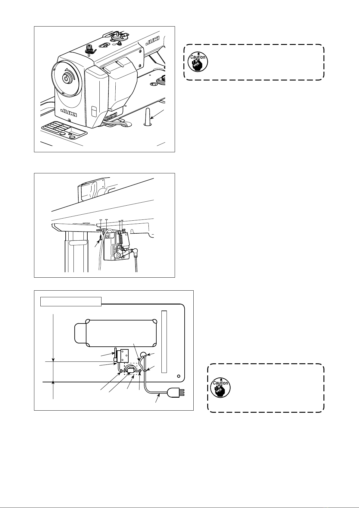
2-4. Installing the pedal sensor ................................................................................................. 4
2-5. Connecting the connector .................................................................................................. 5
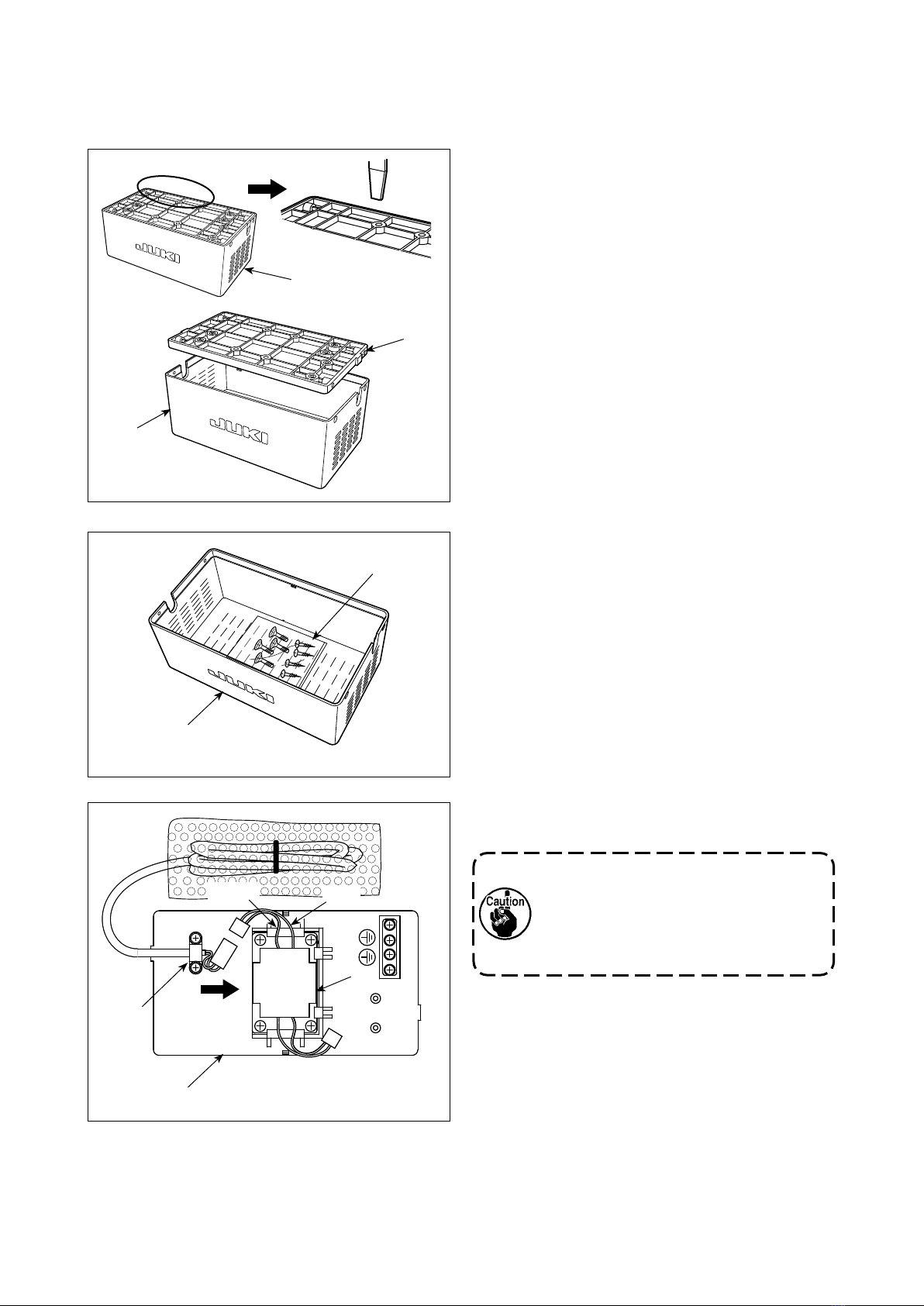
2-6. Installing the reactor box [Only for the EU type models] ................................................ 6
2-7. Installing the power switch................................................................................................. 9
2-7-1. 3-phase 200 to 240V, Single phase 100 to 120V...................................................................... 9
2-8. Installing the thread stand................................................................................................ 11
2-9. Attaching the connecting rod........................................................................................... 11
2-10. Adjustment of the pedal.................................................................................................... 12
2-10-1. Installing the connecting rod................................................................................................ 12
2-10-2. Adjusting the pedal angle ..................................................................................................... 12
2-11. Pedal operation.................................................................................................................. 12
2-12. Power switch...................................................................................................................... 13
2-13. Lubrication ......................................................................................................................... 15
3. PREPARATION BEFORE SEWING .............................................................................. 16
3-1. Attaching the needle ......................................................................................................... 16
3-2. Removing/tting the bobbin case.................................................................................... 16
3-3. Winding the bobbin thread ............................................................................................... 17
3-4. Threading the machine head............................................................................................ 18
3-5. Thread tension................................................................................................................... 18
3-5-1. Adjusting the needle thread tension......................................................................................18
3-5-2. Adjusting the bobbin thread tension ..................................................................................... 18
3-6. Presser foot pressure ....................................................................................................... 19
3-7. Adjusting the stitch length ............................................................................................... 19
3-8. Changing the sewing speed ............................................................................................. 20
3-9. LED hand light ................................................................................................................... 21
3-10. Reverse feed stitching ...................................................................................................... 21
3-11. Adjusting the amount of oil (oil splashes) in the hook .................................................. 22
3-11-1. Adjusting the amount of oil in the hook...............................................................................22
3-11-2. How to conrm the amount of oil (oil splashes)................................................................. 23
3-11-3. Sample showing the appropriate amount of oil.................................................................. 23
3-12. Adjusting the thread take-up spring and the thread take-up stroke............................. 24
4. FOR THE OPERATOR................................................................................................... 25
4-1. How to set the machine head and to initialize data (the factory-set state at the time
of shipment)....................................................................................................................... 25
i

4-2. Operation panel ................................................................................................................. 26
4-3. Audio guidance.................................................................................................................. 28
4-4. Setting the clock................................................................................................................ 29
4-5. Operating procedure of the sewing pattern.................................................................... 30
4-5-1. Reverse feed stitching pattern ...............................................................................................30
4-5-2. Overlapped stitching pattern ..................................................................................................31
4-5-3. Polygonal-shape stitching pattern .........................................................................................32
4-6. Function setting................................................................................................................. 34
4-7. Setting the function keys (F1 and F2).............................................................................. 35
4-8. Production support function ............................................................................................ 36
4-8-1. How to set the production support parameters.................................................................... 36
4-8-2. List of production support parameters.................................................................................. 37
4-8-3. How to display the operation rate of the sewing machine................................................... 38
4-8-4. How to display the number of pieces produced ................................................................... 39
4-9. Function setting list .......................................................................................................... 40
4-10. Detailed explanation of selection of functions ............................................................... 45
4-11. How to use the bobbin counter........................................................................................ 51
4-12. Initialization of function setting data ............................................................................... 52
4-13. Password lock ................................................................................................................... 53
4-14. About the USB ................................................................................................................... 54
4-14-1. Insertion position of the USB thumb drive.......................................................................... 54
4-14-2. Upgrading of the program by means of a USB ................................................................... 55
5. ADJUSTMENT OF THE MACHINE HEAD (APPLICATION) ........................................ 56
5-1. Needle-to-hook relationship ............................................................................................. 56
5-2. Adjusting the needle thread presser device ................................................................... 57
5-3. Adjusting the thread trimmer ........................................................................................... 60
5-3-1. For checking of the thread trimming cam timing ................................................................. 60
5-3-2. Adjustment of the thread trimming cam timing .................................................................... 60
5-3-3. Checking of the knife unit .......................................................................................................61
5-3-4. Adjustment of the knife unit....................................................................................................62
5-4. Adjusting the main shaft stop position ........................................................................... 63
5-5. Grease shortage warning ................................................................................................. 64
5-5-1. Grease shortage warning........................................................................................................ 64
5-5-2. Grease shortage error ............................................................................................................. 64
5-5-3. How to reset the grease shortage error................................................................................. 65
5-6. Disposal of batteries ......................................................................................................... 66
6. CARE ............................................................................................................................. 67
6-1. Cleaning the area around the hook ................................................................................. 67
6-2. Cleaning the interior of the frame .................................................................................... 68
6-3. Applying grease................................................................................................................. 69
6-4. Applying grease to the needle bar lower bushing.......................................................... 69
6-5. Optional devices................................................................................................................ 70
7. LIST OF ERROR CODES .............................................................................................. 72
ii

– 1 –
1. SPECIFICATIONS
• The sewing speed will vary depending on the sewing conditions. The sewing speed preset at the time of
shipping is 4,000 sti/min.
*1 : Needle used depends on the destination.
1-1. Specications of the sewing machine head
1-2. Specications of the control box
Supply
voltage
Single phase
220 to 240V
3-phase 200 to 240V
Single phase 100 to 120V
Single phase
220 to 240V CE
Frequency 50Hz/60Hz 50Hz/60Hz 50Hz/60Hz
Operating environment Temperature : 0 to 35˚C
Humidity : 90% or less
Temperature : 0 to 35˚C
Humidity : 90% or less
Temperature : 0 to 35˚C
Humidity : 90% or less
Input 330VA 330VA 170VA
Classication by voltage of electrical box
E
For the Japanese market and export;
3-phase 200-240 V, single-phase 100 - 120 V
KFor export in general and for China;
single-phase 220 -240 V
NCE; single-phase 220 - 240 V
Classication by auto-lifter
AK Provided with an automatic presser foot lifting
device
Space
Not provided with an automatic presser foot
lifting device
Classication by nipper and touch-back mechanism
OB Provided with an one-touch type reverse-feed switch
NB Provided with a thread nipper device and one-touch type
reverse-feed switch
Classication by model
SSimple type
(standard)
B
Better type
(with shorter-thread
remaining feature)
Classication by lubrication
and sewing specication
MS Semi-dry type for medi-
um-weight materials
SH Minute-quantity lubrication type
for heavy-weight materials
SJ Minute-quantity lubrication type
for jeans
DDL-8000A- ○□□◇◇□□▲
DDL-8000A-*MS DDL-8000A-*SH DDL-8000A-*SJ
Max. sewing speed 5,000 sti/min (P = Less than 4)
4,000 sti/min for "P= 4 or more"
4,500 sti/min (P = Less than 4)
4,000 sti/min for "P= 4 or more"
Stitch length 5 mm
Presser foot lift Hand lifter 5.5 mm
Auto lifter 13 mm or more
Audio guidance Provided
Needle *1 1738 Nm65 to 110 (DB × 1 #9 to 18)
134 Nm65 to 110 (DP × 5 #9 to 18)
1738 Nm125 to 160 (DB × 1 #20 to 23)
134 Nm125 to 160 (DP × 5 #20 to 23)
Lubricating oil JUKI NEW DEFRIX OIL No.1 or JUKI CORPORATION GENUINE OIL 7
Motor AC servo motor
Noise
*MS ;
- Equivalent continuous emission sound pressure level (LpA) at the workstation:
A-weighted value of 78.7 dBA ; (Includes KpA = 2.5 dBA) ; according to ISO 10821-
C.6.2 -ISO 11204 GR2 at 4,000 sti/min.
*SH ;
- Equivalent continuous emission sound pressure level (LpA) at the workstation:
A-weighted value of 82.0 dBA ; (Includes KpA = 2.5 dBA) ; according to ISO 10821-
C.6.2 -ISO 11204 GR2 at 4,000 sti/min.
DDL-8000A- ○□□◇◇□□▲

2×R10
30
30
60
190
240
297
140
115
50
R20
R20
(525.4) 520
154.6
(138.5)
68.5
±0.5
(172.5)
18
Q Q
Z
Z
Z
Z
X
X
X
X
Y
Y
279 ±1
R18
Y
Y
T
T
U
U
WW
R242.5
R242.5
S
S
(15)
390
100
22.5
136
(22.5)
181
0
-1
110
(244)
80
80
80
R20
R22.5
R30
R30
R18
R22.5
29
R10
R10
R10
R10
R20
R22.5
29
50
50
90
1200
R22.5
40
70
535
R30
R30
R30
R30
R6
R6
(591)
141
139
43
86.5
21.5
21.5
84
18
75
52
9
14
17
55
27.5
195
52.5
90
R27.5
R27.5
360
810
R8
R8
R8
R8
R8
R8
40°
27
R2
C1
C1
R2
R2
40
R2
R2
(6)
W-W
40°
40°
R2
R2
R2
R2
R2
14
10
U-U
17.5
±0.5
X-X(2ヵ所)
Y-Y(2ヵ所)
23.5
±0.5
Z-Z(2ヵ所)
19.5
±0.5
T-T
1
±0.5
X-X部ゴム取付参考図
1.2
±0.5
1.2
±0.5
Y-Y部ゴム取付参考図
21
+0.5
0
20
+0.5
0
S-S
10
±1
∅16
±0.5
∅26
Q-Q
32 ±1
A
BC
E
F
G
H
I
D
– 2 –
2. SET UP
2-1. Drawing of table
(2 locations) (2 locations) (2 locations)
Y-Y
Rubber cushion
installing drawing for
reference
X-X
Rubber cushion
installing drawing for
reference
A4×ø3.4 on the bottom surface, depth 20 (Drill a hole at the time of set-up.)
BInstalling position of drawer stopper (on the reverse side)
Cø17 drilled hole
D3×ø13 drilled hole
E2×ø3.5, depth 10
F2×ø3.5, depth 10
G Through hole
H2×ø3.4 on the bottom surface, depth 10 (Drill a hole at the time of set-up.)
I C1.5 to C2.5 (hinge side only)

×
❻
❹❼
– 3 –
2-2. Cautions when setting up the sewing machine
2-2-1. How to carry the sewing machine
Carry the sewing machine while holding the machine
arm with two persons as shown in the gure.
1. Never hold the handwheel since it
rotates.
2. Be sure to handle the sewing ma-
chine with two persons or more since
the sewing machine weighs 40 kg or
more.
2-2-2. Caution when placing the sewing ma-
chine
Place the sewing machine on a horizontal and plane
place when placing it and do not place any protrud-
ing thing such as a screwdriver or the like.
Do not hold the handwheel.
2-3. Installation
Thank you very much for the purchase of JUKI Industrial Sewing Machine this time. Make sure of items 2-1
through 2-13 before operating to use this sewing machine with ease.
1) The under cover ❹ should rest on the four cor-
ners of the machine table groove. Mount rubber
hinge seat ❺ on the table and x it on the table
with a nail.
2) Fix two rubber seats ❶on side A(operator’s
side) using nails ❷ as illustrated above. Fix two
cushion seats ❸on side B(hinged side) using a
rubber-based adhesive. Then place under cover
❹ on the xed seats.
3) Fit hinge ❼ into the opening in the machine bed,
and t the machine head to table rubber hinge
seat ❺ before placing the machine head on cush-
ions ❻ on the four corners.
❶
❸
❺
❶
❸
23.5 mm 19.5 mm
❶
❹
❸
AB
❷
1.2 ± 0.5 mm
1.2 ± 0.5 mm
1 ± 0.5 mm

❹
❶
❶❹
❹
❸
❷
❹
❺
Pedal sensor
Slack
Underside of the table
Eu-type
120mm-130mm
– 4 –
Be sure to mount the machine head sup-
port rod
❹
on the machine table so that
its height from the table surface becomes
56 to 60 mm.
4) Securely attach head support rod ❹ to the table
until it goes no further.
2-4. Installing the pedal sensor
1) Install the pedal sensor to the table with mounting
screws ❶ supplied with the unit.
It is necessary to install the pedal sensor at such
a position that the connecting rod is perpendicular
to the table.
2) After the completion of installation of the pedal
sensor on the table, place the sewing machine
head on the table.
3) Secure pedal sensor cable ❶and AC
input cable ❷with staples ❹.
[EU-type models]
Install ring core ❺.
For one ring core ❺, clamp the pedal
sensor cable ❶ after winding the cable
round the torus of the ring core three
times.
The lateral position of the pedal
sensor should be adjusted so
that the connecting rod is posi-
tioned straight. Then, secure the
pedal sensor at that position.

❸
❶
❷
❶
– 5 –
2-5. Connecting the connector
WARNING :
• To protect against personal injury resulting from abrupt start of the sewing machine, be sure to turn
the power OFF, unplug the machine and wait for ve minutes or more before installing the pedal
sensor.
• To prevent damage of device caused by maloperation and wrong specications, be sure to connect
all the corresponding connectors to the specied places. (If any of the connectors is inserted into a
wrong connector, not only the device corresponding to the connector can break but also it can start
abruptly, inviting the risk of personal injury.)
• To prevent personal injury caused by maloperation, be sure to lock the connector with lock.
• Do not connect the power plug until the connection of cords is completed.
• Fix the cords while taking care not to forcibly bend them or excessively clamp them with staples.
• As for the details of handling respective devices, read carefully the Instruction Manuals supplied
with the devices before handling the devices.
1. Do not insert the power plug into the
wall outlet.
2. Check to be sure that the power
switch is turned OFF.
3. Be sure to fully insert the connectors
into the corresponding ports until
they are locked.
1) Draw out pedal sensor cable ❶and AC input
cable ❷ coming from the electrical box to the
undersurface of the sewing machine table through
cable draw-out hole ❸.
2) Connect pedal sensor cable ❶and the connector
under the table.

– 6 –
2-6. Installing the reactor box [Only for the EU type models]
* For the EU-type models, install the reactor box that is supplied with the sewing machine.
1) Detach reactor cover ❷ from reactor box ❶to
separate from reactor base asm. ❸.
* The reactor cover can be detached with ease
by inserting a tool that has a thin at tip such
as a at-blade screwdriver between the cover
and base.
2) Take out screw bag ❹ from cover ❷.
* The screw bag contains two dierent kinds of
screws (four pieces each).
3) Slide reactor ❺ in the direction of the arrow to
insert into reactor base asm. ❸.
1. When inserting the reactor, detach
bundled wire clamp ❻ beforehand.
2. Insert reactor ❺ into the reactor base
asm. while facing brown and blue
lead wires side upward.
❺
❸
❷
❷
❻
❸
❹
❶
Blue
Brown

– 7 –
4) Connect the connector ❼ of the power cord that is
xed to reactor base asm. ❸ to the connector of
reactor ❺.
Be sure to insert the former fully into
the latter until the connector is locked.
❸
❼
❺
❸
❺
5) Take out wood screws (ST4.2 x 25) from screw
bag ❹. Secure reactor base asm. ❸and reactor
❺ to the undersurface of sewing machine table
with the wood screws (at four locations).
Refer to the instruction gure shown in
the following step of procedure 11) for
the mounting positions of the reactor
cover and reactor base asm.
7) Connect the connector of power cord asm. ❽to
connector of reactor ❺.
8) Secure earth terminal of power cord asm. ❽to
earth base with a screw.
Secure the earth terminal to the screw
with earth mark .
❾
❽
❸
❹
❽
❺
6) Secure power cord asm. ❽ coming from the elec-
trical box to reactor base asm. ❸ with bundled
wire clamp ❾.

– 8 –
11) Install accessory ring cores .
For two ring cores , clamp the power cord of
the electrical box after winding the cable round the
torus of the ring core twice.
12) Fix input/output cables and of reactor box
❶ on the table stand using accessory cord staple
.
At this time, take care not to cross the input- and
output-cables .
Operator's side
Power box
❶
Undersurface of table
9) Fit reactor cover ❷over reac-
tor base asm. ❸.
10)Take out reactor cover xing screws from screw
bag ❹. Secure reactor cover ❷ to reactor base
asm. ❸ with the xing screws (at four locations).
220-250mm
❹
❸
❷
Take care not to allow the cord to be caught under reactor cover ❷.
Pass the power cord through cord bushing . Then, insert the power cord into the slit portion
of reactor cover ❷ and hold it with reactor base asm. ❸.
❷
❸

– 9 –
2-7. Installing the power switch
Do not insert the power plug into the
plug receptacle.
2) Remove screw ❹ on the side face of the power
switch cover to open the power switch cover.
3) Pass AC input cord ❺,through the rear face of
the power switch. Bundle the cord with cable clip
band ❻ to secure it.
WARNING :
1. Be sure to attach the ground wire (green/yellow) to the specied location (on the ground side).
2. Take care not to allow terminals to come in contact with each other.
3. When closing the power switch cover, take care not to allow the cord to be caught under it.
2-7-1. 3-phase 200 to 240V, Single phase 100 to 120V
Voltage specications at the time of delivery from the factory are indicated on the voltage indication seal.
Connect the cord in accordance with the specications.
1) Installing the power switch
Fix power switch ❶ under the machine table with
wood screws ❷.
Fix the cable with staples ❸supplied with the ma-
chine as accessories in accordance with the forms
of use.
❶
❷
❸
❹
❺
❻

– 10 –
4) Securely x the terminals of the AC input cord by tightening the screws at the specied locations.
• Connecting 3-phase 200 to 240V
• Connecting single phase 100 to 120V
AC200 to 240V
Black
Green/Yellow
Green/Yellow
Table
Control box
Power switch
White
White
Green/Yellow —GND
White
Black
Red
Black
Green/Yellow
Green/Yellow
Power switch
Control box
Table
White
Brown
Light blue
Black Red
Red
Red
5) Close the power switch cover. Tighten screw ❹ on the side face of the power switch cover.
1. Be sure to prepare the power plug
which conforms to the safety stan-
dard.
2. Be sure to connect the ground lead
(green/yellow) to the grounding side.
Blue
Brown
Green / Yellow
(ground wire)
AC 220-240V
• 1ø 220-240V
6) Check that the power switch is in the OFF state.
Then, insert the power plug ❼ coming from the
power switch into the plug receptacle.
In prior to the connection of the power
plug ❼, re-check the supply voltage
specication indicated on the control
box.
* The power plug ❼ is dierent in shape accord-
ing to the destination of the sewing machine.
❼

❶
❹❸
❸
❷
❶
– 11 –
2-8. Installing the thread stand
1) Assemble the thread stand unit, and in-
sert it in the hole in the machine table.
2) Tighten nut ❶.
2-9. Attaching the connecting rod
Fix connecting rod ❶to installing hole ❹ of pedal
lever ❷with nut ❸.
WARNING :
To protect against possible personal injury due to abrupt start of the machine, be sure to start the
following work after turning the power o and a lapse of 5 minutes or more.

❷
❹
❹
❷
❶
❸
A
C
E
D
B
(Neutral
position)
– 12 –
2-10-1. Installing the connecting rod
1) Move pedal ❸ to the right or left as illustrated by
the arrows so that motor control lever ❶and con-
necting rod ❷ are straightened.
2-10-2. Adjusting the pedal angle
1) The pedal tilt can be freely adjusted by changing
the length of the connecting rod ❷.
2) Loosen adjust screw ❹, and adjust the length of
connecting rod ❷.
2-10. Adjustment of the pedal
WARNING :
Turn OFF the power before starting the work so as to prevent accidents caused by abrupt start of the
sewing machine.
2-11. Pedal operation
The pedal is operated in the following four steps :
1) The machine runs at low sewing speed when you
lightly depress the front part of the pedal. B
2) The machine runs at high sewing speed when
you further depress the front part of the pedal. A
(If the automatic reverse feed stitching has been
preset, the machine runs at high speed after it
completes reverse feed stitching.)
3) The machine stops (with its needle up or down)
when you reset the pedal to its original position.
C
4) The machine trims threads when you fully depress
the back part of the pedal. E
* When the auto-lifer (AK device) is used, one more operating switch is provided between the sewing ma-
chine stop switch and thread trimming switch.
The presser foot goes up when you lightly depress the back part of the pedal D, and if you further depress
the back part, the thread trimmer is actuated.
When starting sewing from the state that the presser foot has been lifted with the Auto-lifter and you de-
press the back part of the pedal, the presser foot only comes down.
• If you reset the pedal to its neutral position C during the automatic reverse feed stitching at seam start,
the machine stops after it completes the reverse feed stitching.
• The machine will perform normal thread trimming even if you depress the back part of the pedal immedi-
ately following high or low speed sewing.
• The machine will completely perform thread trimming even if you reset the pedal to its neutral position C
immediately after the machine started thread trimming action.
5) When you depress lightly the back part of pedal at its neutral position C before starting, the pedal is
brought to the rst presser lifting position D. When you depress the back part of pedal further, the pedal is
brought to the second presser lifting position E.

1) Turning the power ON with the power switch
The power to the sewing machine is placed in the
ON state when the "|" mark side of power switch
❶ (1ø 220 - 240V type) is pressed; or in the OFF
state when the "0" mark side is pressed.
The power to the sewing machine is placed in the
ON state when the ON button of power switch ❷
(3ø 200 - 240V type) is pressed; or in the OFF
state when the OFF button is pressed.
The power to the sewing machine is placed in the
ON state when the knob of power switch ❸(EU
type, 1ø 220 - 240V type) is turned by 90 degrees
counterclockwise; or in the OFF state when it is
turned clockwise to return to its home position.
1. Do not strongly tap the power switch
by hand.
2. If the power indicator LED on the
panel does not light up after having
turned ON the power switch, immedi-
ately turn OFF the power switch and
check the supply voltage.
When you want to re-turn ON power
switch after carrying out the afore-
mentioned steps, it is necessary to
wait for ve minutes or more after
you have turned OFF power switch.
3. Do not place your hand or anything
under the needle since the needle bar
may automatically move according
to the memory switch setting when
you turn ON the power to the sewing
machine.
2-12. Power switch
* The switch conguration diers with the specications.
Single phase
220 to 240V
3-phase 200 to 240V,
Single phase 100 to 120V
EU-Type model
Single phase 220 to 240V
❶
❷
❸
– 13 –

2) When you depress the back part of
pedal, the needle bar and the presser
lifting motor carry out their initial oper-
ation to allow the sewing machine to
start sewing.
If you attempt to start sew-
ing without depressing the
back part of pedal, the warn-
ing message screen shown
below will be displayed. To
prevent this, be sure to start
sewing after depressing the
back part of pedal.
< Origin retrieval screen >
6) After the completion of sewing, check to make sure that the sewing machine has stopped. Then, press
power switch ❶or ❷(or turn EU-type power switch ❸) to turn it OFF.
– 14 –
In the case the machine is not used for a long time, remove the power plug from the plug recep-
tacle.

❶
– 15 –
Fill the oil tank with oil for hook lubrication before
operating the sewing machine.
1) Turn ON the power switch. Remove oil hole cap
❶. Pour NEW Defrix Oil No. 1 (part number:
40214221 or MDFRX16000C0) supplied with the
unit or JUKI CORPORATION GENUINE OIL 7 (part
number: 40102087) into the oil tank through the
oil hole.
2) When the oil amount in the oil tank reaches the
maximum amount, ashes on and o on the
operation panel and the voice warning is
given.
Stop oiling.
If the oil is lled excessively, it will leak from the
air vent hole in the oil tank or proper lubrication
will be not performed. In addition, when the oil is
vigorously lled, it may overow from the oil hole.
So, be careful.
2-13. Lubrication
WARNING :
1. Do not connect the power plug until the lubrication has been completed so as to prevent accidents
due to abrupt start of the sewing machine.
2. To prevent the occurrence of an inammation or rash, immediately wash the related portions if oil
adheres to your eyes or other parts of your body.
3. In the case of adding oil to the sewing machine while it is energized, do not place your hands into
the moving parts for the sake of safety.
1. When you use a new sewing machine or a sewing machine after an extended period of dis-
use, use the sewing machine after performing break-in at 2,000 sti/min or less.
2. For the oil for hook lubrication, purchase JUKI NEW DEFRIX OIL No. 1 (part number : MD-
FRX1600C0) or JUKI CORPORATION GENUINE OIL 7 (part number : 40102087).
3. Be sure to lubricate clean oil.
4. Do not operate the machine with the oil hole cap ❶ removed. Never remove cap ❶ from the
oil inlet in any case other than oiling. In addition, take care not to lose it.
3) When the remaining amount of oil in the oil tank is reduced while the sewing machine is in use, the warn-
ing screen is displayed on the operation panel as shown below, the LED at the top of the operation panel
ickers and the voice warning is given. The warning screen can be reset with the reset button ❶.
❶

C
DB
A
❷
❶
D
B
C
A
– 16 –
Use the specied needle for the machine. Use the
proper needle in accordance with the thickness of
thread used and the kinds of the materials.
1) Turn the handwheel until the needle bar reaches
the highest point of its stroke.
2) Loosen screw ❷, and hold needle ❶with its
indented part A facing exactly to the right in direc-
tion B.
3) Insert the needle fully into the hole in the needle
bar in the direction of the arrow until the end of
hole is reached.
1) Turn the handwheel to lift the needle above the
throat plate.
2) Install the bobbin in the bobbin case so that the
thread wound direction is clockwise.
3) Pass the thread through thread slit A of the bob-
bin case, and pull the thread in direction C. By
so doing, the thread will pass under the tension
spring and come out from notch B.
4) Check that the bobbin rotates in the direction of
the arrow when thread is pulled.
5) Pinching latch D of the bobbin case with ngers,
t the bobbin case in the hook.
3. PREPARATION BEFORE SEWING
3-1. Attaching the needle
3-2. Removing/tting the bobbin case
WARNING :
Turn OFF the power before starting the work so as to prevent accidents caused by abrupt start of the
sewing machine.
WARNING :
Turn OFF the power before starting the work so as to prevent accidents caused by abrupt start of the
sewing machine.
4) Securely tighten screw ❷.
5) Check that long groove C of the needle is facing exactly to the left in direction D.

E
F
❻
❼
❻
❺
❻
❽
BB
❷
A
C
D
❹
❶
❸
– 17 –
1) Insert the bobbin deep into the bobbin winder
spindle ❶ until it will go no further.
2) Pass the bobbin thread pulled out from the spool
rested on the right side of the thread stand follow-
ing the order as shown in the gure on the left.
Then, wind clockwise the end of the bobbin thread
on the bobbin several times.
3) Press the bobbin winding lever ❷in the direction
of A and start the sewing machine. The bobbin
rotates in the direction of B and the bobbin thread
is wound up. The bobbin winder spindle ❶auto-
matically as soon as the winding is nished.
4) Remove the bobbin and cut the bobbin thread
with the thread cut retainer ❸.
5) When adjusting the winding amount of the bob-
bin thread, loosen setscrew ❹ and move bobbin
winding lever ❷ to the direction of Cor D. Then
tighten setscrew ❹.
To the direction of C: Decrease
To the direction of D: Increase
6) In case that the bobbin thread is not wound evenly
on the bobbin, remove the handwheel, loosen
screw ❺ and adjust the height of bobbin thread
tension ❽.
3-3. Winding the bobbin thread
• It is the standard that the center of the bobbin is as high as the center of thread tension disk ❻.
• Adjust the position of thread tension disk ❻ to the direction of E when the winding amount of the bobbin
thread on the lower part of the bobbin is excessive and to the direction F when the winding amount of
the bobbin thread on the upper part of the bobbin is excessive.
After the adjustment, tighten screw ❺.
7) To adjust the tension of the bobbin winder, turn the thread tension nut ❼.
1. When winding the bobbin thread, start the winding in the state that the thread between the
bobbin and thread tension disk ❻ is tense.
2. When winding the bobbin thread in the state that sewing is not performed, remove the nee-
dle thread from the thread path of thread take-up and remove the bobbin from the hook.
3. There is the possibility that the thread pulled out from the thread stand is loosened due to
the inuence (direction) of the wind and may be entangled in the handwheel. Be careful of
the direction of the wind.
This manual suits for next models
1
Table of contents
Other JUKI Sewing Machine manuals

JUKI
JUKI HZL-F series User manual

JUKI
JUKI K-1E User manual

JUKI
JUKI HZL-K85 User manual

JUKI
JUKI MB-1800 series Quick start guide

JUKI
JUKI DNU-1541-7 User manual

JUKI
JUKI AMS-229B User manual

JUKI
JUKI SC-956A User manual

JUKI
JUKI MO-6900G Series User manual

JUKI
JUKI AK-157 User manual

JUKI
JUKI DDL-8700-7 User manual

JUKI
JUKI LK-1900AN Quick start guide

JUKI
JUKI MC-35 User manual

JUKI
JUKI MO-623 User manual

JUKI
JUKI PLC-2710V User manual

JUKI
JUKI PS-800-13085 User manual

JUKI
JUKI MO-1200QVP User manual

JUKI
JUKI AMS-343B User manual

JUKI
JUKI HZL-X Series User manual

JUKI
JUKI L-1D Series User manual

JUKI
JUKI K-1E User manual