– 4 –
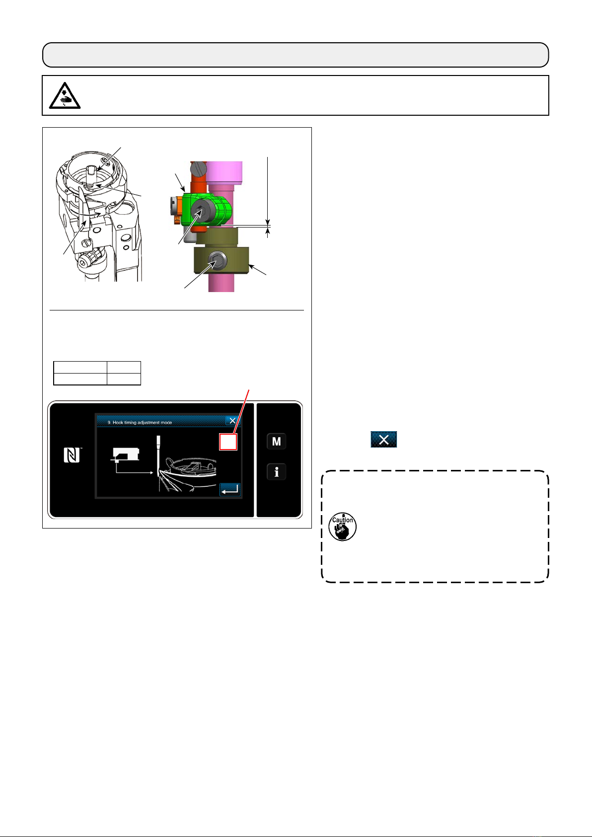
When a hook has been replaced, be sure to check the
position of the hook needle guard.
As the standard position of the hook needle guard, hook
needle guard must push the side face of needle to
lean the needle by 0.05 to 0.2 mm away from its straight
position.
If the aforementioned standard state is not achieved,
insert a screwdriver (small) into needle guard ad-
justment screw and adjust the position of the needle
guard.
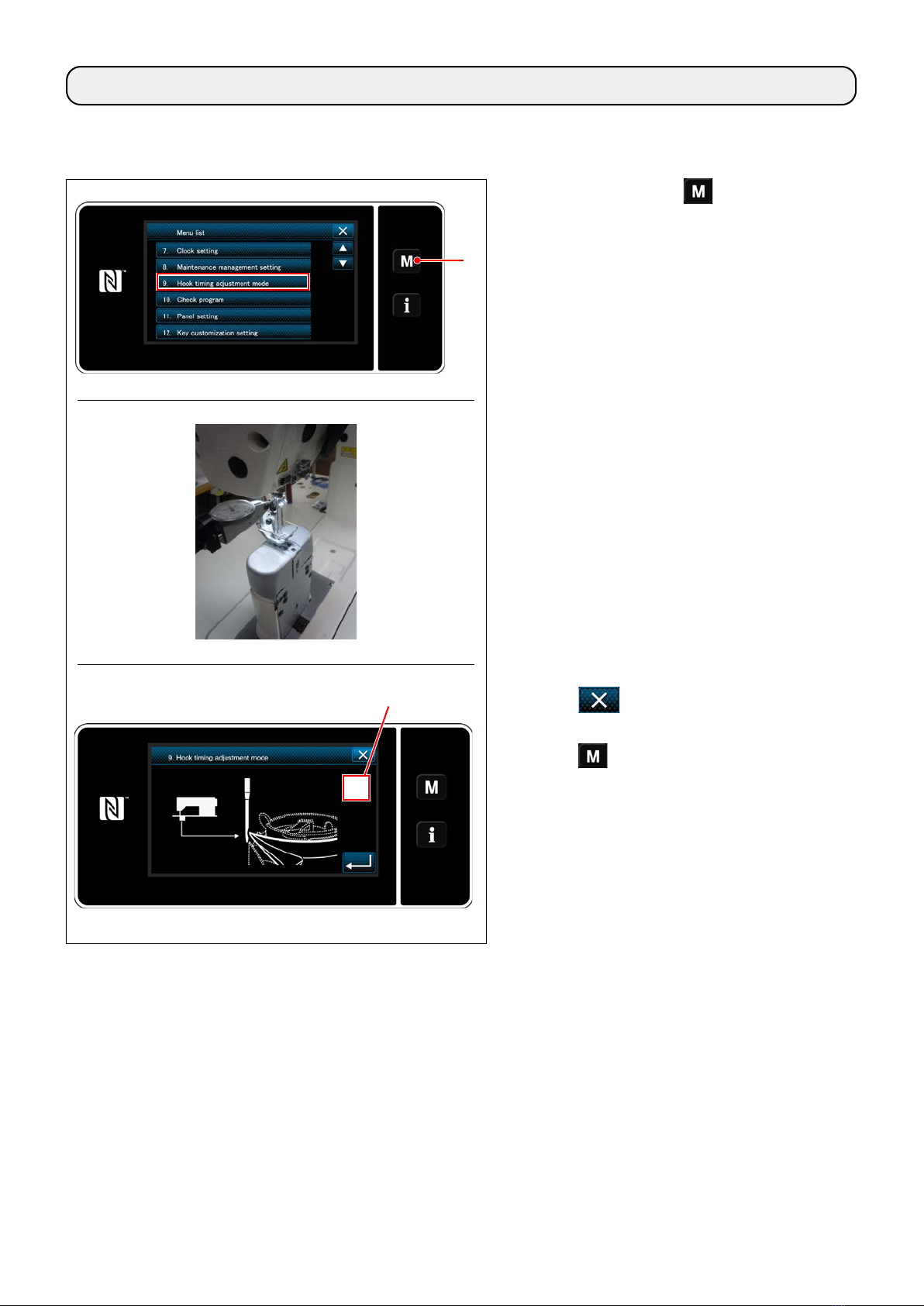
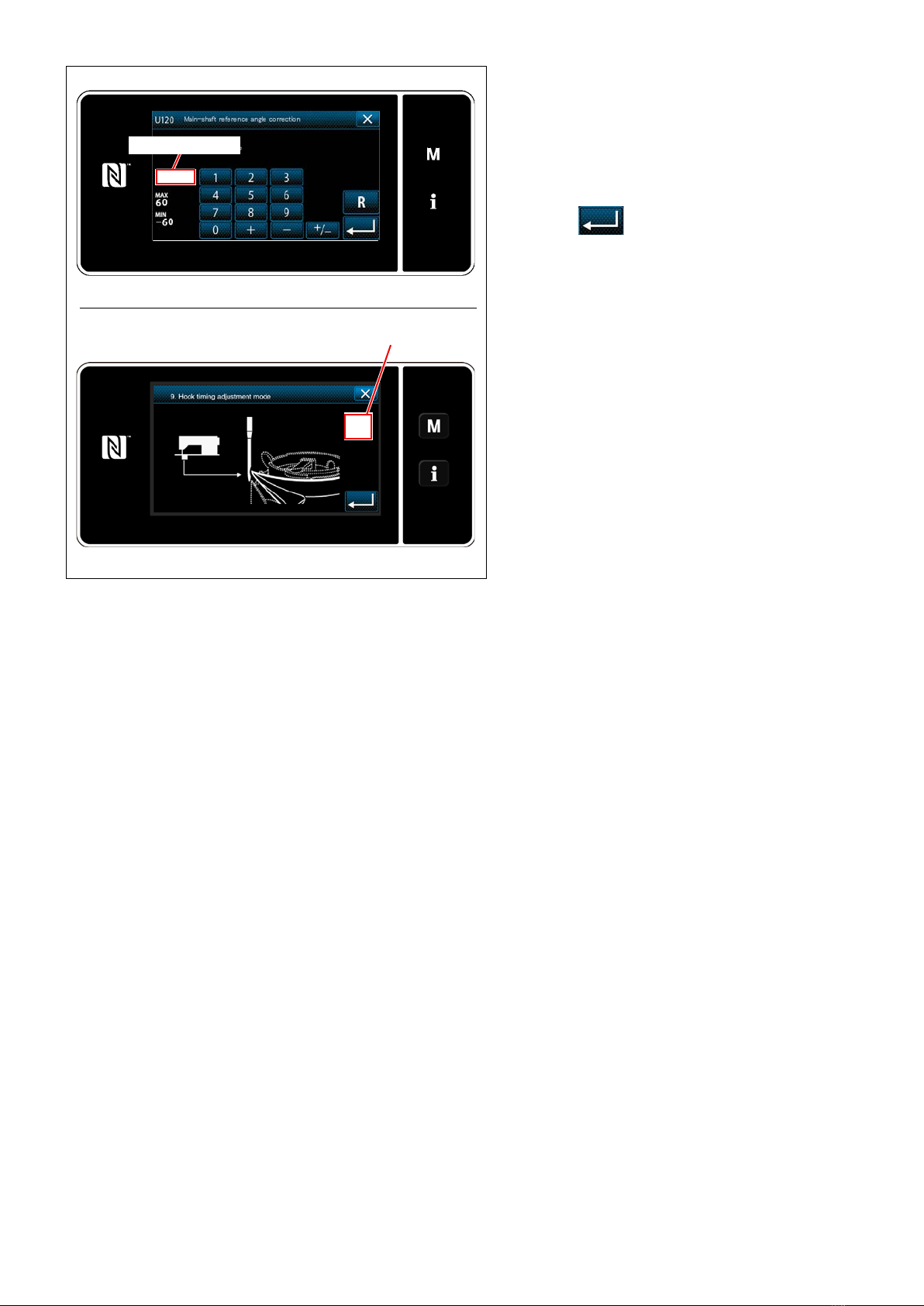
1) Place the machine in the hook timing adjustment
mode.
2) To bend the hook needle guard in direction a, turn
the needle guard adjusting screw in direction A.
0.05 to
0.2 mm
BA
ab
A
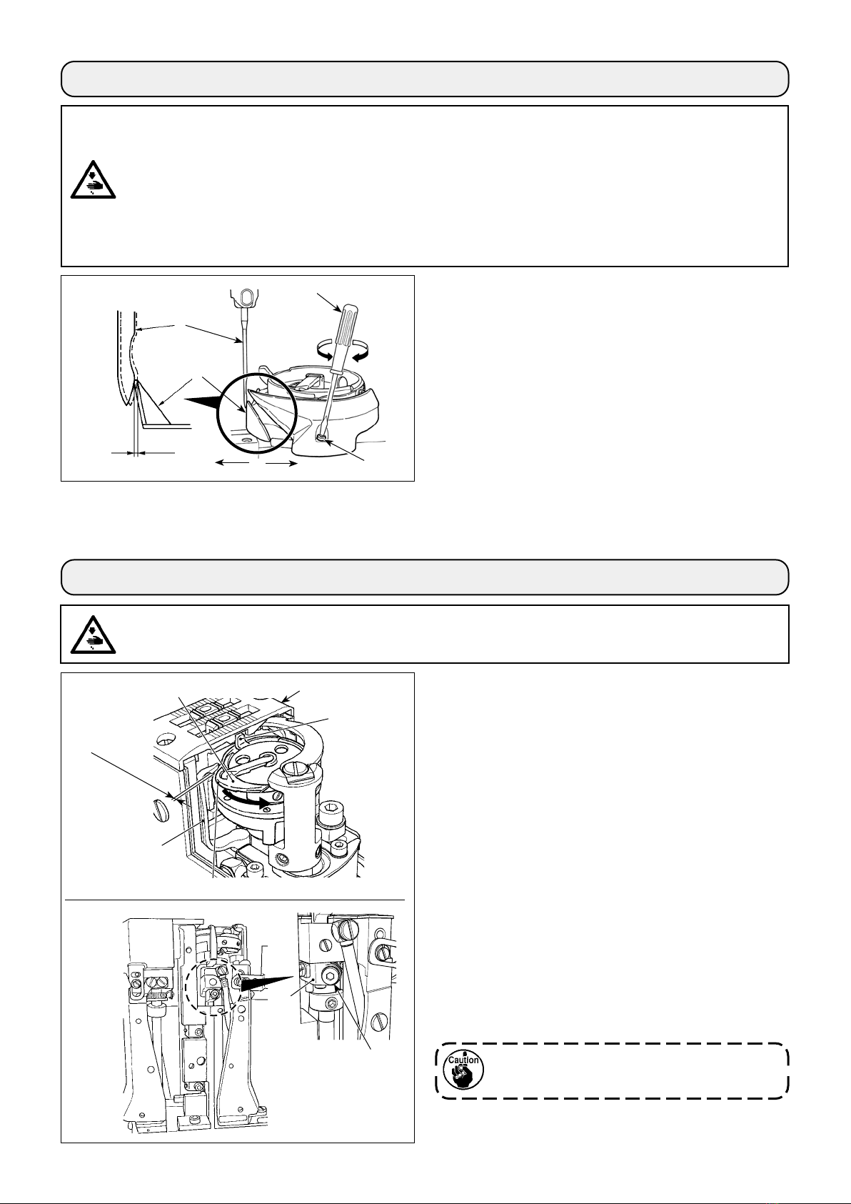
0.2 to 0.3 mm
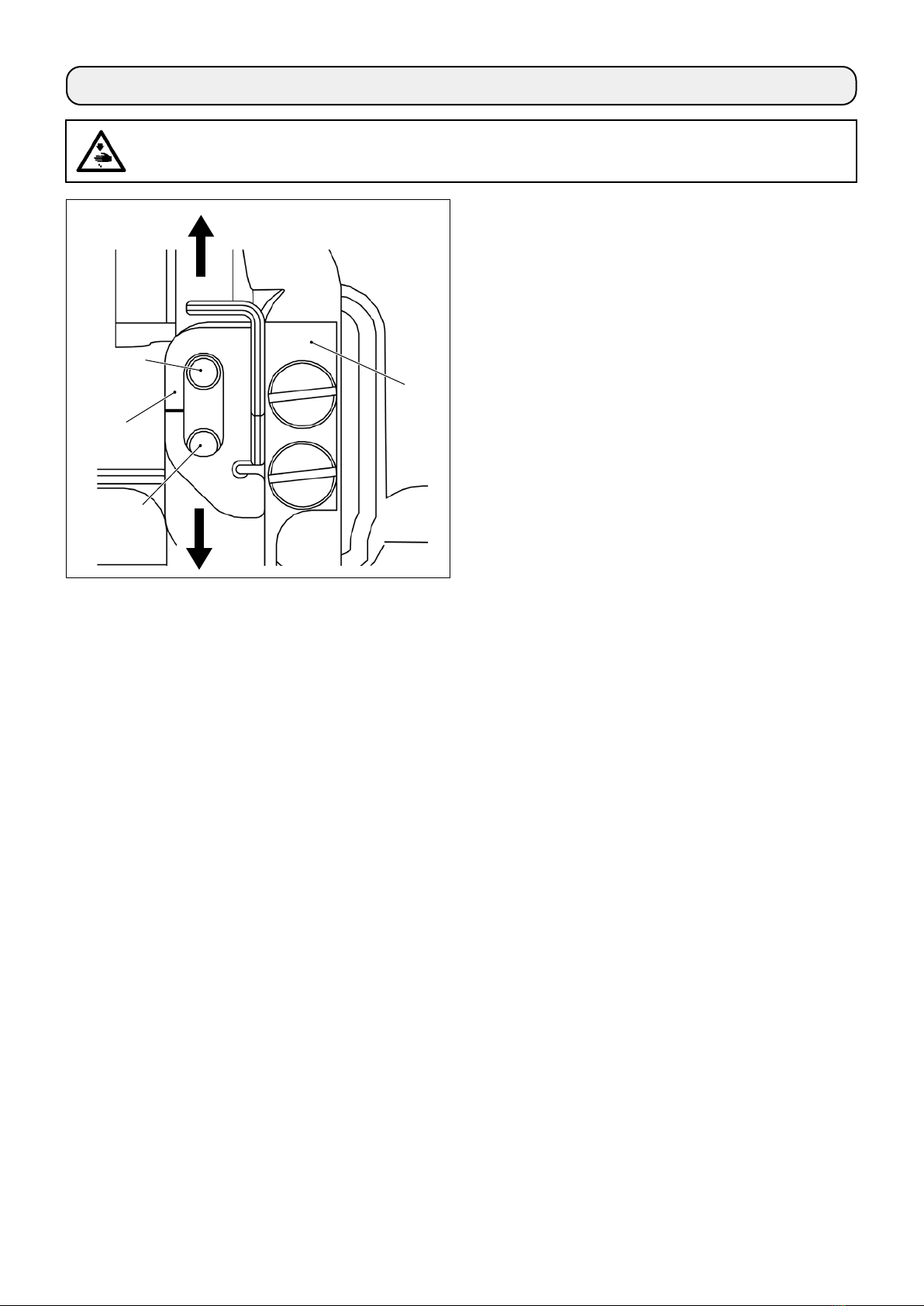
1) Open the hook cover. (How to open : move the
hook cover to the right or left after lifting it right
above.)
2) Turn the handwheel in its normal rotational direc-
tion to bring bobbin case opening lever to its
back end position.
3) Turn inner hook in the direction of the arrow
until stopper is pressed against the slits in throat
plate .
4) Loosen bobbin case opening lever crank setscrew
. Adjust the clearance between the bobbin case
opening lever and protruding portion Aof the bob-
bin case to 0.2 to 0.3 mm.
5) Tighten setscrew while pressing down bobbin
case opening lever crank .
6) Move inner hook guide up and down to make
sure that there is not play in the thrust direction.
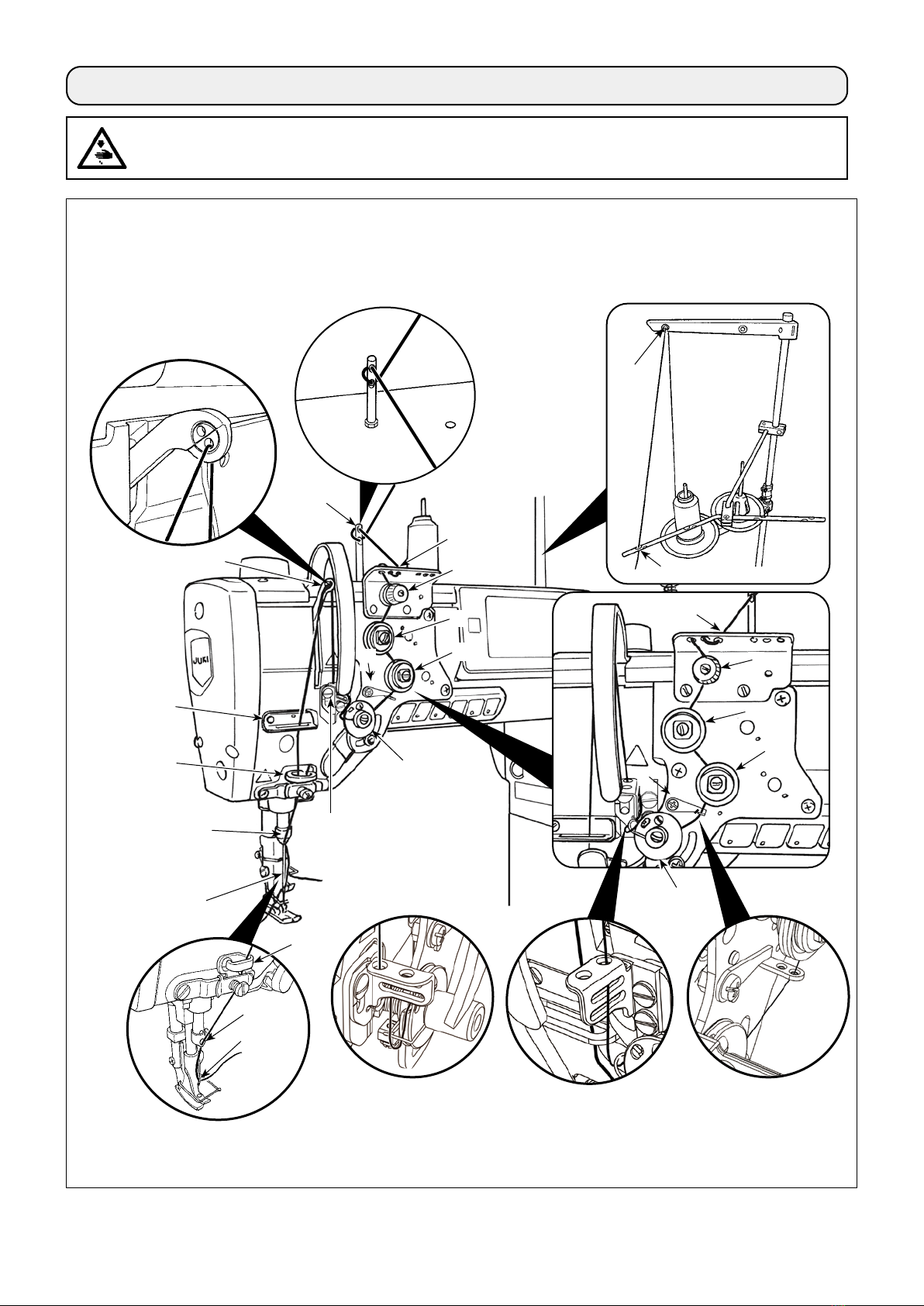
WARNING :
To protect against possible personal injury due to abrupt start of the machine, be sure to start the following
work after turning the power o and ascertaining that the motor is at rest.
5. Adjusting the bobbin case opening lever
In case of 2-needle machine, perform the
same adjustment to the right and left hooks.
4. Adjusting the hook needle guard
3) To bend the hook needle guard in direction b, turn the needle guard adjusting screw in direction B.
4) At the nal step of procedure, appropriately ad-just the clearance provided between the needle and the hook.
WARNING :
To protect against possible personal injury due to abrupt start of the sewing machine, be sure to change
over the operation mode to the "hook timing adjustment mode".
The presser foot automatically goes up when changing over the operation mode to the "hook timing
adjustment mode". In addition, the presser foot also comes down when the "hook timing adjustment
mode" is nished and the power is turned OFF. Be sure carry out the operation while keeping your hands,
etc. away from the presser foot.
For the sewing machine which is provided with the stitch skipping detecting device, the light emitted by
the sensor LED may light into the eye to cause dazzling when adjusting the hook timing.
To avoid this, cover the LED before adjusting the hook timing.