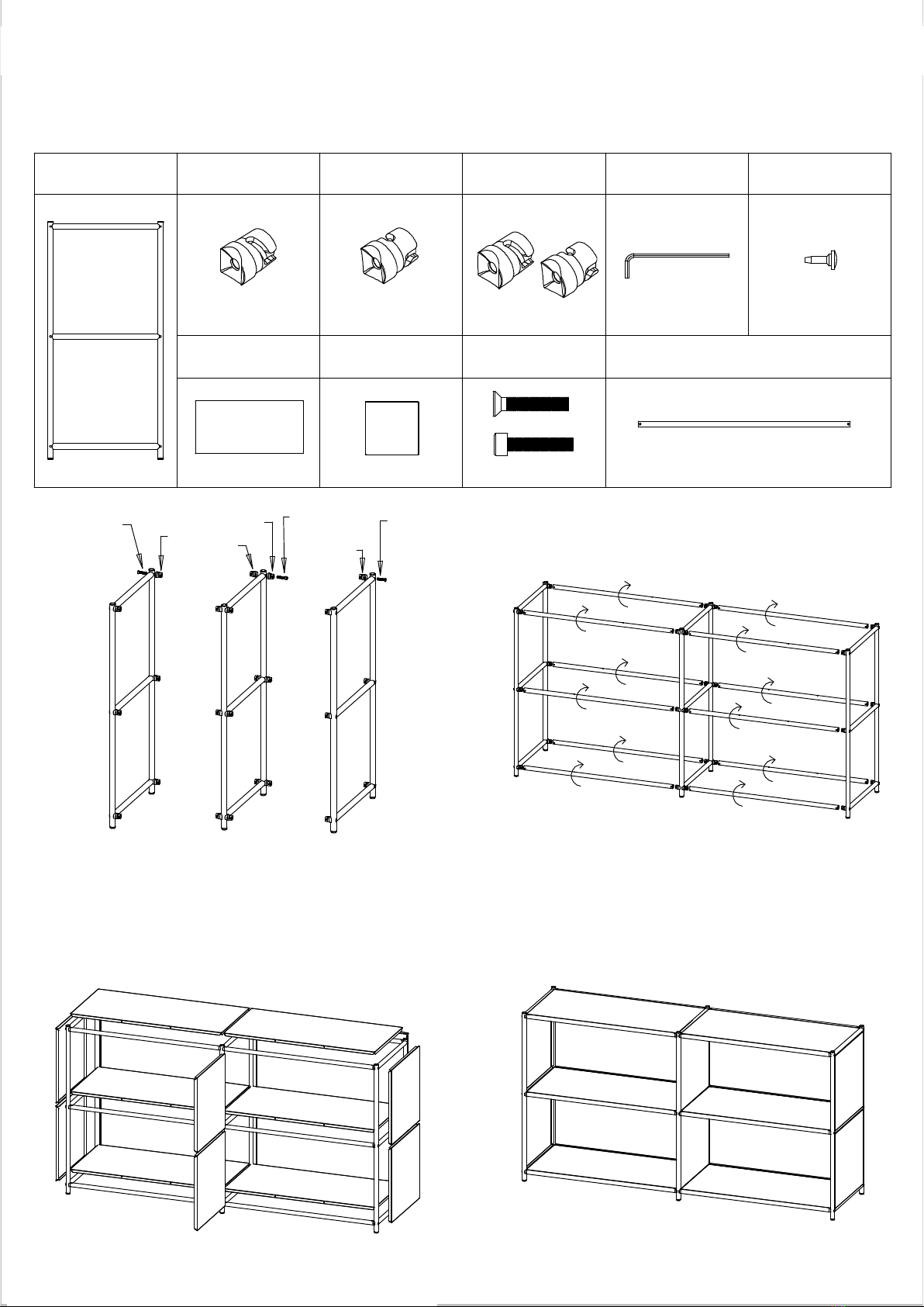
3. Press one side corner into the frame and then others,
Socket cap
* Fix the R connector to the inside of frame D with a screw.
M connector x6
panels by hand into horizontal tubes.
* Fix the R connector to the left side and M connector to
the right side of frame B with a flat screw.
2. Attach the horizontal tube to the connector and
then rotate it by 90 degrees by hand.
B
Socket cap
A
Vertical frame x3
screw
pat the panel corner in one by one.
750 mm Horizontal tube x12
4. Insert rubber stoppers for 750 mm floor
R connector x6
RR
screw
LM
*Make sure that screw holes of horizontal
C
tube 750 mm are facing inward.
* L connector for left side
* R connector for right side
Assembly Instructions
stopper x24
Rubber
M4 Hex screwdriver X1
R connector x6L connector x6
750 mm Steel
panel x6 Flat head screw X6
panel x10
Socket cap screw X12
the frame B.
* Fix the connectors to the frame C in the same order as
*Make sure that the concave holes on both
sides of the horizontal tube are facing up.
375 mm Steel
Flat
head
screw
Causion:
1. * Fix the L connector to the inside of frame A with a screw.
Causion:
* M connectors for extention only
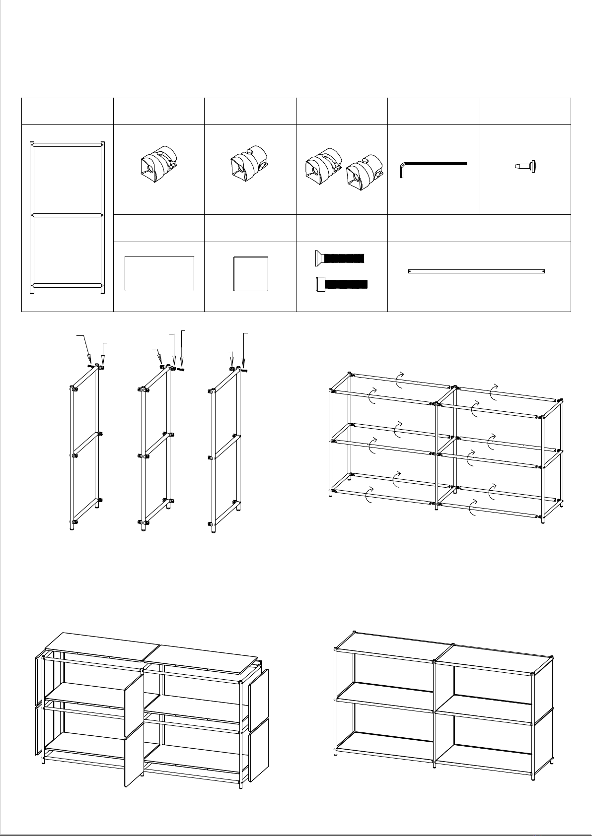
Model No.: SF-2215
Modellnummer: SF-2215
Montageanleitung
Vertikaler Rahmen x3 L-Verbindungsstecker x6 M-Verbindungsstecker x6
R-Verbindungsstecker x6
R-Verbindungsstecker x4 M4 Innensechskantschlüs-
sel X1 Gummi-Stopfen x24
750 mm Stahlblech x10 375 mm Stahlblech x6 Innensechskantschraube x12
Flachkopfschraube x6 750 mm horizontales Rohr x12
Innen-
sechskant-
schraube
Innensechs-
kantschraube
Flach-
kopf-
schraube
1. * Befestigen Sie den L-Verbindungsstecker mit einer Schraube an der
Innenseite von Rahmen A.
* Befestigen Sie den R-Verbindungsstecker an der linken Seite und
den M-Verbindungsstecker an der rechten Seite von Rahmen B mit-
hilfe einer Flachkopfschraube.
* Befestigen Sie die Verbindungsstecker am Rahmen C in der glei-
chen Reihenfolge wie am Rahmen B.
*Befestigen Sie den R-Verbindungsstecker mit einer Schraube an der
Innenseite von Rahmen D.
Achtung: * L-Verbindungsstück für linke Seite
* R-Verbindungsstecker für die rechte Seite
* M-Verbindungsstecker nur für Erweiterung
2. Befestigen Sie das horizontale Rohr an den Verbindungsste-
ckern und drehen Sie es dann von Hand um 90 Grad.
Achtung: * Stellen Sie sicher, dass die konkaven Löcher an beiden Seiten des
horizontalen Rohrs nach oben zeigen.
* Stellen Sie sicher, dass die Schraubbohrungen des horizontalen
750-mm-Rohrs nach innen weisen.
3. Drücken Sie zuerst eines der Seitenbleche in den Rahmen und
dann die anderen; klopfen Sie die Ecken der Bleche nacheinan-
der fest.
4. Gummistopfen für 750 mm Bodenblech von Hand in horizontale
Öffnungen einlegen.