screw
* Fix the R connector to the inside of frame D with a screw.
* R connector for right side
* Fix the connectors to the frame C in the same order as
the frame B.
L connector x8
Socket cap
tube 750 mm are facing inward.
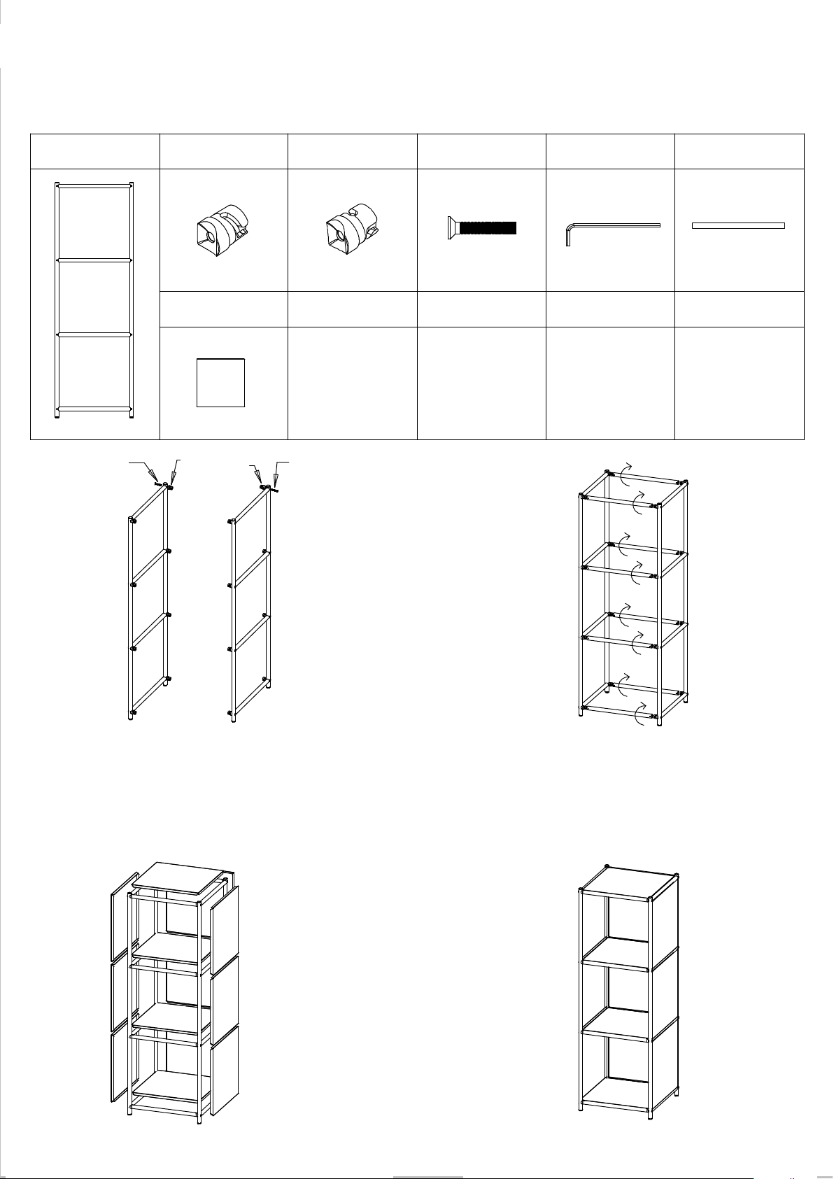
Assembly Instructions
2. Attach the horizontal tube to the connector and
then rotate it by 90 degrees by hand.
pat the panel corner in one by one.
B
* Fix the R connector to the left side and M connector to
the right side of frame B with a flat screw.
* L connector for left side
screw
A
Model No.: SF-3137
*Make sure that screw holes of horizontal
R
panels by hand into horizontal tubes.
tube x8
M4 Hex screwdriver X1R connector x8
Vertical frame x2 375 mm Horizontal
*Make sure that the concave holes on both
panel x13
sides of the horizontal tube are facing up.
3. Press one side corner into the frame and then others, 4. Insert rubber stoppers for 750 mm floor
Socket cap screw X16
375 mm Steel
Socket cap
L
1. * Fix the L connector to the inside of frame A with a screw.
Causion:
Causion:
* M connectors for extention only
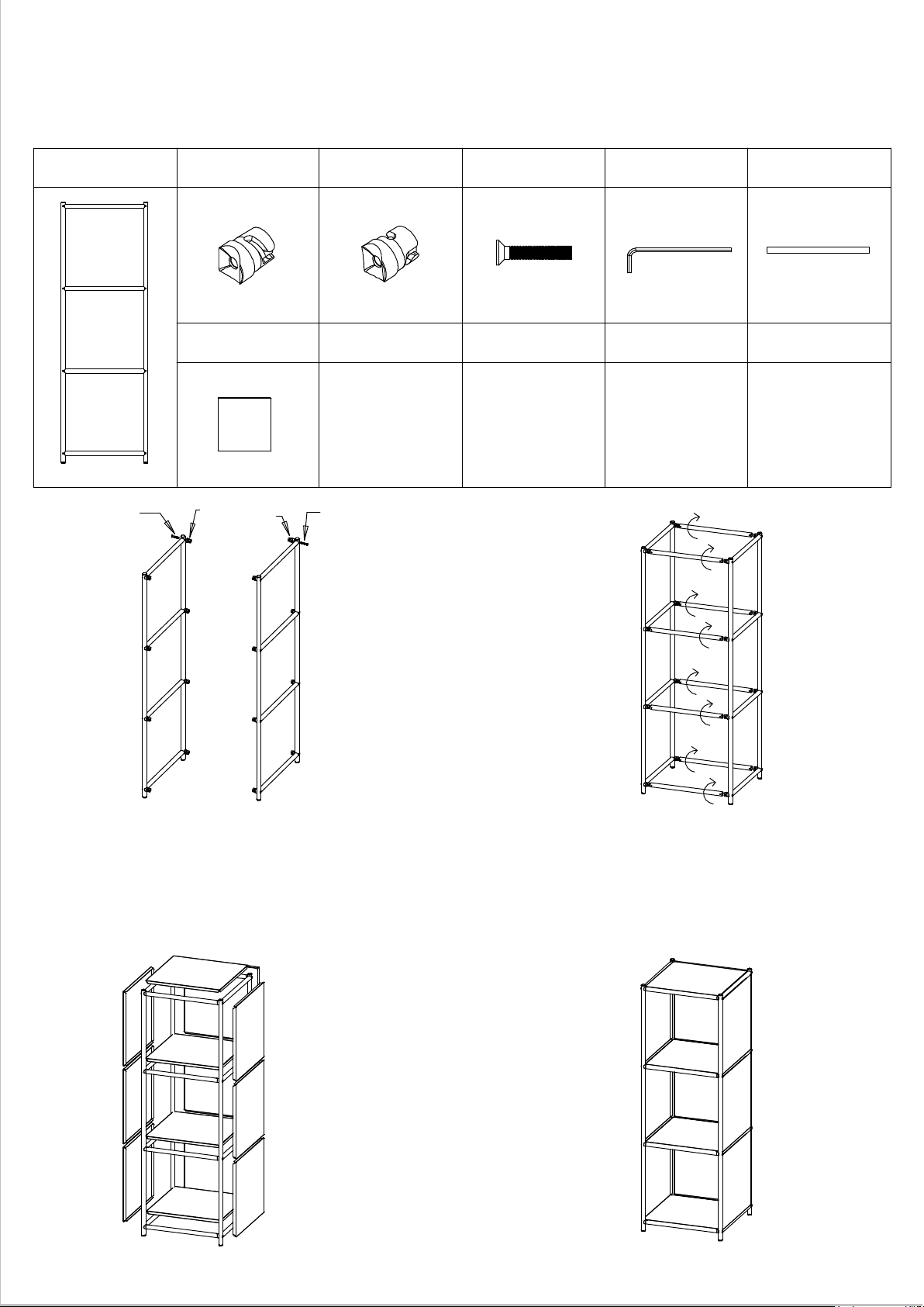
Modellnummer: SF-3137
Montageanleitung
Vertikaler Rahmen x2 L-Verbindungsstecker x8 Innensechskant-
schraube x16
R-Verbindungsstecker x8 M4 Innensechskantschlüs-
sel X1
375 mm horizontales
Rohr x8
375 mm Stahlblech x13
Innen-
sechskant-
schraube
Innensechs-
kantschraube
1. * Befestigen Sie den L-Verbindungsstecker mit einer Schraube an der
Innenseite von Rahmen A.
* Befestigen Sie den R-Verbindungsstecker an der linken Seite und den
M-Verbindungsstecker an der rechten Seite von Rahmen B mithilfe einer
Flachkopfschraube.
* Befestigen Sie die Verbindungsstecker am Rahmen C in der gleichen Reihen-
folge wie am Rahmen B.
*Befestigen Sie den R-Verbindungsstecker mit einer Schraube an der
Innenseite von Rahmen D.
Achtung: * L-Verbindungsstück für linke Seite
* R-Verbindungsstecker für die rechte Seite
* M-Verbindungsstecker nur für Erweiterung
2. Befestigen Sie das horizontale Rohr an den Verbindungsste-
ckern und drehen Sie es dann von Hand um 90 Grad.
Achtung: * Stellen Sie sicher, dass die konkaven Löcher an beiden
Seiten des horizontalen Rohrs nach oben zeigen.
* Stellen Sie sicher, dass die Schraubbohrungen des horizon-
talen 750-mm-Rohrs nach innen weisen.
3. Drücken Sie zuerst eines der Seitenbleche in den Rahmen und
dann die anderen; klopfen Sie die Ecken der Bleche nacheinan-
der fest.
4. Gummistopfen für 750 mm Bodenblech von Hand
in horizontale Öffnungen einlegen.