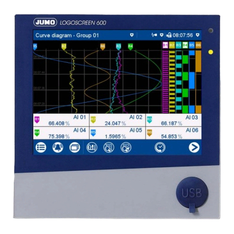
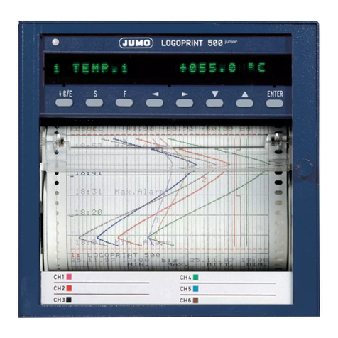
JUMO LOGOSCREEN 500 User manual

Paperless recorder
B 95.5015
Operating Instructions
04.02/00378469


Contents
1 Introduction 5
1.1 Preface .......................................................................................................... 5
1.2 Arrangement of the documentation ........................................................... 6
1.2.1 Structure of these Operating Instructions ...................................................... 6
1.3 Typographical conventions ......................................................................... 7
1.3.1 Warning signs ................................................................................................. 7
1.3.2 Note signs ...................................................................................................... 7
1.3.3 Representation ............................................................................................... 8
2 Instrument description 9
2.1 Display and controls .................................................................................... 9
2.2 Operating principle and graphic elements .............................................. 10
2.3 Analog inputs .............................................................................................. 12
2.4 Event traces ................................................................................................ 13
2.5 Counters / Integrators / Timers ................................................................ 14
2.5.1 Reporting periods of counts ........................................................................ 16
2.5.2 Resetting the counters / integrators / timers ............................................... 16
2.5.3 Behavior on instrument reconfiguration ....................................................... 17
2.6 Math / logic module ................................................................................... 18
2.7 Operating modes ........................................................................................ 21
2.8 Data storage ............................................................................................... 22
3 Operation and visualization 23
3.1 Basic menu ................................................................................................. 24
3.2 Visualization ................................................................................................ 25
3.2.1 Diagram representation with digital display (small measurement) ............... 26
3.2.2 Diagram representation with scaling ............................................................ 27
3.2.3 Diagram representation with bargraph ......................................................... 27
3.2.4 Large digital display (large measurement) .................................................... 28
3.2.5 Curve representation (header switched off) ................................................. 28
3.2.6 Evaluating the stored measurement data .................................................... 29
3.2.7 Counters / integrators / operating time ........................................................ 32
3.3 Parameter setting ....................................................................................... 33
3.4 Configuration .............................................................................................. 35
Contents
3.5 Event list ...................................................................................................... 36
3.6 Disk manager .............................................................................................. 38
3.7 Instrument info ........................................................................................... 41
3.8 Text input ..................................................................................................... 43
3.9 Code number (password entry) ................................................................ 44
4 Configuration parameters 47
4.1 Operating example ..................................................................................... 47
4.2 Table of configuration parameters ........................................................... 48
4.2.1 Parameter setting ......................................................................................... 48
4.2.2 Configuration - Instrument data ................................................................... 49
4.2.3 Configuration - Analog inputs ...................................................................... 52
4.2.4 Configuration - Event traces ........................................................................ 54
4.2.5 Configuration - Counter/Integrator (option) ................................................. 55
4.2.6 Configuration - Measurement storage ......................................................... 59
4.2.7 Configuration - Outputs (option) .................................................................. 60
4.2.8 Configuration - Operating functions ............................................................. 61
4.2.9 Configuration - Texts .................................................................................... 61
4.2.10 Configuration - Interface ............................................................................. 62
4.2.11 Configuration - Fine calibration .................................................................. 62
5 Setup program 65
5.1 Hardware and software requirements ...................................................... 65
5.2 Installing the setup program ..................................................................... 66
5.3 Data exchange between paperless recorder and PC ............................. 67
5.3.1 Data transfer via diskette ............................................................................. 67
5.3.2 Data transfer via setup interface .................................................................. 68
5.4 Math and logic module .............................................................................. 69
5.5 Character set .............................................................................................. 72
6 PC evaluation program 75
6.1 Program description .................................................................................. 75
7 Identifying the instrument version 77
7.1 Type designation ........................................................................................ 77

Contents
7.2 Standard accessories ................................................................................ 78
7.3 Optional accessories ................................................................................. 78
8 Installation 79
8.1 Location and climatic conditions .............................................................. 79
8.2 Mounting in position .................................................................................. 79
9 Electrical connection 81
9.1 Installation notes ........................................................................................ 81
9.2 Technical data ............................................................................................. 81
9.3 Connection diagram .................................................................................. 82
10 TÜV Report on Data Manipulation Security 85
11 Index 89

Contents

5
1 Introduction
1.1 Preface
Please read these Operating Instructions before commissioning the instru-
ment. Keep the operating instructions in a place which is accessible to all us-
ers at all times.
Please assist us to improve these operating instructions where necessary.
Your suggestions will be most welcome.
Phone in Germany (0661) 6003-725
abroad (+49) 661 6003-0
Fax in Germany (0661) 6003-681
abroad (+49) 661 6003-607
HAll necessary settings are described in this manual. If any difficul-
ties should still arise during commissioning, you are asked not to
carry out any unauthorized manipulations on the unit. You could
endanger your rights under the instrument warranty!
Please contact the nearest subsidiary or the main factory in such a
case.
EWhen returning modules, assemblies or components, the regula-
tions of EN 100 015 “Protection of electrostatically sensitive com-
ponents” must be observed. Use only the appropriate ESD pack-
aging for transport.
Please note that we cannot accept any liability for damage caused
by ESD (electrostatic discharge).
B

1 Introduction
6
1.2 Arrangement of the documentation
The documentation for this instrument consists of the following parts:
Operating
Instructions
B 95.5015
These operating instructions are included in the delivery. They are addressed
to the equipment manufacturer (OEM), and to the user with appropriate techni-
cal expertise.
In addition to installation and electrical connection, they contain information
on commissioning, operation and parameter setting on the instrument, as well
as on the optional PC setup programm and the optional PC evaluation pro-
gram (PCA).
Interface
Description
B 95.5015.2
It provides information on the serial interfaces (RS232 and RS485), which can
be supplied as an extra. Using the interface description, it is possible to devel-
op specific programs which can, for instance, read out current measurement
data.
1.2.1 Structure of these Operating Instructions
These operating instructions are arranged in a way which permits the user to
enter directly into the operation and configuration of the instrument. Conse-
quently, chapters dealing with items that normally arise only once are placed
at the end of the manual. These include instrument description, type designa-
tion, installation and electrical connection.

7
1 Introduction
1.3 Typographical conventions
1.3.1 Warning signs
The signs for Danger and Caution are used in this manual under the following
conditions:
V
Danger
This sign is used when there may be danger to personnel if the instructions
are disregarded or not followed accurately!
ACaution
This sign is used when there may be damage to equipment or data if the in-
structions are disregarded or not followed accurately!
E
Caution
This sign is used where special care is required when handling electrostati-
cally sensitive components.
1.3.2 Note signs
HNote
This sign is used where your special attention is drawn to a remark.
vReference
This sign refers to further information in other handbooks, chapters or sec-
tions.
abc1Footnote
Footnotes are notes which refer to certain points in the text.
Footnotes consist of two parts:
Marking in the text and the footnote text.
The marking in the text is arranged as continuous superscript numbers.
h
Action
This sign marks the description of a required action.
The individual steps are indicated by this asterisk, e. g.:
hPress the hkey
hConfirm with E

1 Introduction
8
1.3.3 Representation
h+ E
Keys
Keys are shown in a frame. Both symbols or text are possible. Where a key
has multiple functions, the text shown corresponds to the function which is
currently active.
Program
manager
Screen text
Texts displayed in the setup program are shown in italics.
Edit !
Instrument data
Menu items
Menu items of the setup program, which are referred to in this manual, are
shown in italics. Menu item and sub-menu item are each separated by “!”.

9
2 Instrument description
2.1 Display and controls
1. not from the configuration level,
if a parameter has already been altered there.
HThe life of the background illumination can be prolonged by using
the screen saver.
vChapter 4 “Configuration parameters”,
Parameters !Display off
Status LED (red)
is on continuously while
an alarm is present
Enter
- select menu item
- enter input
Menu
back to the basic menu1
Exit
- previous window
- cancel
current action
Menu-dependent function keys (softkeys)
screen-dependent function, represented by text or symbols
Color display
320 x 240 pixel, 27 colors
Cover
of the disk drive
for opening the disk drive
cover
Power LED (green)
is on continuously as
soon as power is applied;
flashes when the screen
saver is activated.

2 Instrument description
10
Opening and
closing the
housing door
2.2 Operating principle and graphic elements
Keys The recorder is operated from eight keys. Three of these have fixed functions,
the other five (softkeys) have menu-dependent functions.
vChapter 2.1 “Display and controls”
Softkeys The softkey functions appear in the bottom line of the display, as symbols or in
plain language.
The housing door can
be opened or closed
by turning the knob
Status line
Header

11
2 Instrument description
Status line The status line is shown in the upper part of the display. It provides information
on important actions and states.
The status line is always visible, irrespective of the level (operation, parame-
ters, configuration).
Time & Date
shows the actual time and
date
The egg timer appears whenever the instrument is busy and
can therefore not be operated.
The “H” informs you that the indicated measurements are
derived from the past (history). The data saved in the
FLASH memory are shown.
In the event of an error, an “i” flashes here.
The cause of the error can be read out from the instrument
info window (vChapter 3.7 “Instrument info”).
If the keys are inhibited, a key flashes in this position
Alarm
If an alarm has occured (e. g. out-of-limit),
the (alarm) bell flashes in this field
shows last entry in event list
Instrument name (16 characters max.)
Current diagram speed
Background color:
gray = normal operation,
blue = timed operation,
orange = event operation
Diskette / internal memory
Indicates the free storage capacity of the diskette or the internal
memory in percent. If there is a diskette error, the diskette symbol
flashes. The error message can be checked in the disk manager.
In the event of a “memory alarm”, the field is shown
with a yellow background.
vChapter 3.6 “Disk manager”
Storage capacity of diskette
available internal memory

2 Instrument description
12
Channel line
(channel
representation)
The channel line shows the measurements of the active channels and their unit
as
- measurement
-scalingor
-bargraph.
Alternatively, the header can be switched off altogether.
In addition, alarms and out-of-limit conditions are made directly visible, ac-
cording to the display mode.
Example: Measurement (meas. small)
The selection and visual presentation of the channel line can be controlled by
using the parameter Parameters ➔Diagram view ➔Channel representation.
2.3 Analog inputs
Internal
analog inputs
The paperless recorder can be equipped with 3 or 6 analog inputs. When con-
figuring the analog inputs (Chapter 4.2 “Table of configuration parameters”),
these are designated analog input 1 — 3 (1 — 6).
Numerical display
The measurements are shown in numerical form.
OFF
If a channel is switched off, then
there will be no indication.
Unit of measurement
Alarm
If an alarm is present (e. g. out-of-limit), the measurement
of the channel is shown on a red background.
Overrange
Underrange
State of
event traces

13
2 Instrument description
2.4 Event traces
Signal types In addition to the four logic inputs (extra code), digital signals generated by the
instrument itself can also be displayed in the six event traces:
Representation Representation on the screen is as follows:
Signal Description
Logic input 1 — 4 Four logic inputs present in hardware
(extra code)
Logic channel 1 — 6 Channels which are created by using the math
and logic module (instrument software version
133.03.xx or higher and extra code are required)
Low alarm 1 — 6 Underlimit of channels
Low combination alarm OR linkage of all low alarms
High alarm 1 — 6 Overlimit of channels
High combination alarm OR linkage of all high alarms
Counter/integrator alarm 1 — 6 Limit infringements of counter/integrator
channels (instrument software version 133.03.xx
or higher and extra code are required)
Counter/integrator
combination alarm
OR linkage of all counter/integrator
alarms (instrument software version 133.03.xx or
higher and extra code are required)
Combination alarm OR linkage of all low and high alarms
Memory alarm Alarm is triggered when the residual capacity of
the diskette, or the available internal storage spa-
ce, falls below a certain value.
Chapter 3.6 “Disk manager”
Error Alarm when the battery is discharged, or the time
has to be reset.
Chapter 3.7 “Instrument info”
Modbus-Flag Control flag which can be activated through the
serial interface.
Representation
as symbol On/Off represented as switch:
as diagram Representation as time sequence:

2 Instrument description
14
Outputs The digital signals can be used to operate the three relays (extra code). It is
possible to configure the action as n.c. (break) or n.o. (make)
(Configuration ➔Outputs).
External texts So-called “external texts” can be arranged through four logic inputs. Either a
standard text or one of the 18 definable texts can be used. The instrument au-
tomatically supplements the texts in order to distinguish between the appear-
ance and disappearance of the signal. The external texts are configured on the
instrument under Configuration ➔Operating functions.
vChapter 3.5 “Event list”
Event operation The digital signals can be used to activate event operation. In event operation,
the measurements are stored at a storage rate which is different from that in
normal operation.
2.5 Counters / Integrators / Timers
Counters, integrators and timers are available as extras from instrument soft-
ware 133.03.xx.
These are not electrical measurement inputs (hardware), but channels which
are calculated by the recorder (software).

15
2 Instrument description
Counters
Counter inputs - logic inputs
- logic channels
-alarms
-errors
- Modbus-Flag (signal via serial interface)
Counter
frequency
30Hz max.
Weighting The count pulses can be evaluated (weighted). A down counter can be imple-
mented by entering a negative weighting (e.g. weighting factor -1).
Each count change can be documented with an entry in the event list. The
new count is attached to the message.
Integrators
Integrator
inputs
- analog inputs 1— 3 (6)
Integrator
time base
- sec, min, hr and day
Weighting You can also enter a weighting for the integrators.
Weighting
example
- flow measurement
- input signal from 0 — 20mA (corresponds to 0 — 1000 l/sec)
- time base 1sec
- weighting 0.001
- display of the integration value (quantity) in m³
Minimum size
of input signal
Entering a threshold value (amount of threshold value) has the effect that inte-
gration takes place only when the value has been exceeded. No integration
will occur on falling below the value. The advantage of integration with a
threshold value larger than 0 is that possible noise from a transducer can be
suppressed in this way.
Timers
The timer will count for as long as the selected logic input or one of the digital
signals is closed (set). The time can be displayed in sec, min, hr and days.

2 Instrument description
16
2.5.1 Reporting periods of counts
After an adjustable time period (reporting period) the counts are stored for all
counters/integrators/timers. The counts of the most recently concluded re-
porting period can be graphically displayed. The following counter/integrator
types are possible:
-periodic
The time period (between 1 min and 12 hrs) must additionally be selected in
the parameter Period.
-external
The counter/integrator is updated here only when the selected operating
signal is active (e.g. logic input is closed). When the operating signal is de-
activated (e.g. logic input is open), the counter/integrator value is stored
and reset to 0.
- daily
-weekly
-monthly
-yearly
-total
- daily from-to
In addition, the period has to be selected, by means of the parameters
“Daily start time” and “Daily end time”. The counter/integrator will then be
updated from the start time only. When the end time has been reached, the
counter/integrator value is stored and reset to 0.
2.5.2 Resetting the counters / integrators / timers
Periodic reset There is a reporting period for each counter/integrator/timer. At the end of this
period, the current data (value and time) are stored and the value is reset to 0.
Subsequently, the next period can be recorded.
An exception is the totalizer/integrator value. It is stored whenever any count/
integration has been completed, but it is not reset to 0. This enables the total-
izer to be evaluated also in the PCA evaluation software.
External reset You can configure an operating signal for all 6 channels together, with the re-
sult that the counters/integrators are reset to 0 without storing the previous
values. The period for the counter/integrator summation will be restarted at
this point. This means that after the test run of an installation, for instance, the
recording can be freshly started, thereby eliminating the test run values, which
are not required.
vSee “Reset generation” on page 59.
Reset from
keys
Another option of resetting the counter/integrator values is provided at the pa-
rameter level. After entering the password, you can define a value for each of
the 6 channels. The counter/integrator will then be set to this value. When, af-
ter editing, a value is accepted, a message with the new and the old count is
entered in the event list.

17
2 Instrument description
The time period for the counter/integrator summation will not be freshly start-
ed. The previous counter/integrator values will also not be saved.
In this way, you can restart the recording of individual counters/integrators, for
example, after the test run of an installation; the values of the test run, which
are not required, can thus be eliminated.
You can select a password other than that for accessing the configuration. The
password can be set under Configuration
➔
Instrument data
➔
Code
No.(Password)
➔
Counter/Int.reset.
Reset via
the “Disk
manager” menu
If the function Update diskette incl. counters is executed in the “Disk manager”
menu, the counts will also be stored and reset.
vSee “Disk manager” on page 38.
2.5.3 Behavior on instrument reconfiguration
When the instrument is reconfigured, the current counter/integrator reporting
periods remain unaffected. The counter/integrator values will not be reset to 0
and the reporting period will not be restarted.
HIf you wish to save the previous counter/integrator values, you have to
execute the function “Update diskette incl. counters” in the Disk manager
menu before resetting.
HThe values can be deliberately reset via the “Parameters” menu.

2 Instrument description
18
2.6 Math / logic module
The math and logic module is available as an extra from instrument software
133.03.xx. As is the case with the counters/integrators/timers, the math and
logic module, too, are channels that are not available in hardware, but are cal-
culated through the instrument software.
The math and logic module consists of 2 parts:
- the math module for calculating analog values and
- the logic module for calculating boolean values (0 or 1).
Math module Using the math module, measurement inputs can be used to calculate new
“virtual” channels.
There are no separate math channels for the calculated channels, the existing
analog channels 1 — 3 (6) are used instead. In configuration, you have to se-
lect the Mathematics option under the parameter “Sensor” for the required
channel.
Configuration ➔Analog input x ➔Sensor = Mathematics
Each of the 6 channels can either be used for recording the corresponding
channel, or as a math channel. With a 3-channel instrument, three additional
“virtual” channels can thus be created.
When the measurement inputs AE1 and AE2 are mathe-
matically linked, the measurement inputs AE3 — AE5 in
the example above are not available as sensor inputs.
Other manuals for LOGOSCREEN 500
1
Table of contents
Other JUMO Voice Recorder manuals

JUMO
JUMO Logoline 500 junior User manual

JUMO
JUMO LOGOSCREEN Series User manual

JUMO
JUMO LOGOLINE 500d User manual

JUMO
JUMO LOGOSCREEN Series User manual

JUMO
JUMO LOGOSCREEN nt User manual

JUMO
JUMO LOGOSCREEN 600 Reference guide

JUMO
JUMO AQUIS touch S User manual

JUMO
JUMO LOGOSCREEN cf User manual

JUMO
JUMO LOGOSCREEN es User manual

JUMO
JUMO LOGOSCREEN 601 User manual
Popular Voice Recorder manuals by other brands

Philips
Philips POCKET MEMO LFH9600 Specifications

LeuchtKraft
LeuchtKraft RDMX-8 instruction manual

Dictaphone
Dictaphone Walkabout 5210 user guide

Philips
Philips Pocket Memo LFH9380/27 user manual

Vidicode
Vidicode V-Tap Analog 2 quick guide

TS-market
TS-market EDIC-mini Tiny 16 u49 Short operating instructions